EP1342848A2 - Dispositif pour appliquer un revêtement - Google Patents
Dispositif pour appliquer un revêtement Download PDFInfo
- Publication number
- EP1342848A2 EP1342848A2 EP03251305A EP03251305A EP1342848A2 EP 1342848 A2 EP1342848 A2 EP 1342848A2 EP 03251305 A EP03251305 A EP 03251305A EP 03251305 A EP03251305 A EP 03251305A EP 1342848 A2 EP1342848 A2 EP 1342848A2
- Authority
- EP
- European Patent Office
- Prior art keywords
- bar
- plate
- aperture
- fluid material
- side wall
- Prior art date
- Legal status (The legal status is an assumption and is not a legal conclusion. Google has not performed a legal analysis and makes no representation as to the accuracy of the status listed.)
- Withdrawn
Links
Images


Classifications
-
- E—FIXED CONSTRUCTIONS
- E01—CONSTRUCTION OF ROADS, RAILWAYS, OR BRIDGES
- E01C—CONSTRUCTION OF, OR SURFACES FOR, ROADS, SPORTS GROUNDS, OR THE LIKE; MACHINES OR AUXILIARY TOOLS FOR CONSTRUCTION OR REPAIR
- E01C19/00—Machines, tools or auxiliary devices for preparing or distributing paving materials, for working the placed materials, or for forming, consolidating, or finishing the paving
- E01C19/12—Machines, tools or auxiliary devices for preparing or distributing paving materials, for working the placed materials, or for forming, consolidating, or finishing the paving for distributing granular or liquid materials
- E01C19/16—Machines, tools or auxiliary devices for preparing or distributing paving materials, for working the placed materials, or for forming, consolidating, or finishing the paving for distributing granular or liquid materials for applying or spreading liquid materials, e.g. bitumen slurries
Definitions
- the present invention relates to a device for use in the application of fluid materials to surfaces, in particular roads and pavements, and to a method of using the device.
- Conventional surface dressing of roads or pavements involves spraying of a liquid composition, typically "cutback” (diluted bitumen) or bitumen emulsion, via a spray bar attached to the rear of a surface dressing vehicle.
- the liquid composition is fed to the spray bar using a pump system, and is then sprayed on to the road or pavement through nozzles located on the underside of the bar at relatively high temperatures, typically 180-185°C for cutback and 85°C for bitumen emulsion.
- a surfacing device for trailing application of a fluid material to a surface comprises a bar, comprising a leading side wall and a trailing side wall and a cavity therebetween for holding the fluid material, and an underside having an aperture therein, and a plate which, in a first position, closes the aperture and which is downwardly movable to a second position, in which the aperture is open and a further aperture is defined between the plate and the trailing side wall, such that in use the fluid material exits the device through said further aperture.
- a method of applying a fluid material to a surface comprises providing a device of the type defined above containing the fluid material in the cavity of the bar and having the plate in its first position; moving the plate to its second position; and drawing the device over the surface, wherein the size of the further aperture formed, on downwards movement of the plate, between the plate and the trailing edge of the bar is such that the fluid material extrudes from the bar and on to the surface.
- the surfacing device according to the present invention overcomes the afore-mentioned problems associated with conventional spray bars.
- the surfacing material by extrusion, in the form of a substantially smooth laminar flow, rather than in the form of a pressurised spray, airborne contamination is significantly reduced or avoided altogether.
- the surfacing device is less prone to blockage, and can be used to apply surfacing compositions of a range of viscosities and thicknesses.
- the surfacing device according to the present invention may be used to apply a variety of fluid materials to a variety of different surfaces
- the preferred use of the device is in the surface dressing of roads, pavements, car parks and runways.
- the fluid material is typically "cutback" or bitumen emulsion which, after application, may be coated with aggregate to complete the surface dressing operation.
- the device may be used to apply a variety of bitumen emulsion-based materials.
- the device In use, the device will normally be attached to the rear of a conventional surface dressing vehicle, such that it is trailed behind the vehicle and above the surface to be treated. Fluid dressing material is fed to the device via a pump or by gravity, and from there is laid on to the surface. If aggregate is to be applied, this will typically be sourced from a hopper located on the vehicle, or on a second vehicle. When the bar is not in use, the fluid material may be retained in the device or circulated back to a storage tank which, again, may be located on the vehicle.
- the bar in which the fluid material is contained may be manufactured in a fixed width form or in expandable form.
- the bar will typically be square or rectangular in cross-section, although other cross-sectional shapes may be envisaged. While the specific dimensions of the bar are unimportant, for surface dressing applications the bar will typically be 50 mm to 200 mm in width/height, and 2 m to 5 m in length.
- the underside of the bar comprises an aperture through which fluid material exits the bar on to the surface to be treated.
- This aperture may in fact comprise the entirety of the underside of the bar, in other words the underside of the bar may be fully open.
- the underside of the bar may be partially closed, to define one or more distinct apertures.
- the dimension of the aperture may be dictated by the type of fluid material, or the type of surfacing effect desired.
- the aperture in the underside of the bar is closed by a plate which is downwardly movable relative to the bar, to open the aperture and define a further aperture, or gap, between the plate and the trailing side wall of the bar, in the direction of movement of the device across the surface to be treated.
- the size of this further aperture will be relatively small, for instance in the range 1 mm to 40 mm, so that fluid material will effectively be extruded through it and on to the surface to be treated.
- Further downwards movement of the plate, to define a larger aperture between the plate and the trailing side wall of the bar enables easy cleaning of the interior of the bar, for instance to remove bituminous deposits therefrom.
- the plate will form the foot portion of a bracket also comprising an upright section substantially perpendicular to the foot portion.
- the bracket may be attached to the leading side wall of the bar through its upright portion, so that on downwards movement relative to the bar the upright portion of the bracket will effectively extend the leading side wall of the bar, thereby forcing the fluid material out of the back of the bar.
- Movement of the plate, or bracket, relative to the bar may be effected by hydraulic, pneumatic or other means.
- one or more pistons may be used to effect downwards movement of the plate which, if pneumatic, may be run on air from the brakes system of a vehicle to which the surfacing device is attached.
- the or each piston is preferably mounted on the bar itself and is in direct communication with the plate.
- a tight seal is effected between the underside of the bar and the upper surface of the plate so as to prevent leakage of the fluid material. This may be achieved through provision of a seal, for instance made from rubber, which may be attached to the underside of the bar and/or to the upper surface of the plate.
- the surfacing device comprises a plurality of plates which are arranged along the bar and which are independently movable in relation to one another.
- the underside of the bar may comprise a single aperture running substantially along the entirety of its length, or a plurality of independent apertures, each of which is closed by its own plate. In this latter case, it may be desirable to partition the bar into a plurality of chambers, each chamber having an aperture in its underside and being closed by a plate. Movement of the plates may be effected by a plurality of pistons, typically mounted on the bar, each piston controlling the movement of a different plate.
- Such a device is particularly useful for the treatment of uneven or cambered surfaces, as through independent movement of the plates to different extents along the bar different amounts of fluid material may be laid on to the surface, for instance so as to form or retain a camber, or to level an uneven surface, as desired.
- one or more plates may be left in the closed position, thereby effectively shutting off sections of the bar, in order to pattern the surface or to create road-markings.
- the device will typically be made from metal parts, for instance steel or aluminium.
- metal parts for instance steel or aluminium.
- Figure 1 is a cross-sectional view of a device according to the present invention in its closed position, as viewed from one end of the device.
- Figure 2 is a cross-sectional view of a device according to the present invention in an open position, as viewed from one end of the device.
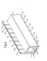
- Figure 3 is a perspective view of one embodiment of the present invention, which is a device comprising a plurality of plates and a bar.
- bracket 1 comprises plate 2 and upright section 3, which is connected to bar 4 via bolt 5.
- Bolt 5 extends from the leading side wall 4A of bar 4 through slot 6 in upright section 3 and is secured by nut 7.
- the movement of nut 7 on bolt 5 is restricted via the action of spring 8, such that the bar is held flush against the upper surface of plate 2 and the upright section 3 therefore closing aperture 10 in the underside of bar 4, as shown in Figure 1.
- plate 2 is lowered via the action of piston 9, which is activated by air from the brakes system of the vehicle (not shown) to which the device is attached, to release the fluid material (not shown) held in cavity 11 on to the surface being treated.
- the fluid material exits cavity 11 through aperture 10 and is extruded through gap 12, which is created between the upper surface of the plate 2 and the trailing side wall 4B of bar 4, as shown in Figure 2.
- it is easily cleaned by lowering plate 2 further, ie. increasing distance 13 between the underside of the bar and the upper surface of the plate, to enable cavity 11 to be easily accessed via aperture 10.
- aperture 10 which extends along the length of the underside of bar 4, is closed by a plurality of independently moveable plates 2A-2H, which are connected to the bar through upright sections 3A-3H to form brackets 1.
- aperture 10 is opened via downwards movement of plates 2A-2H due to the action of a piston associated with each plate (not shown), and the fluid material (not shown) contained in cavity 11 is extruded on to the surface to be treated.
- the aperture 10 may be opened to different extents along the bar, or left closed in some locations, so as to profile the surface to be treated, or apply patterns or markings thereto.
Landscapes
- Engineering & Computer Science (AREA)
- Architecture (AREA)
- Civil Engineering (AREA)
- Structural Engineering (AREA)
- Road Paving Structures (AREA)
- Details Or Accessories Of Spraying Plant Or Apparatus (AREA)
Applications Claiming Priority (2)
| Application Number | Priority Date | Filing Date | Title |
|---|---|---|---|
| GB0205114A GB0205114D0 (en) | 2002-03-05 | 2002-03-05 | Surfacing device |
| GB0205114 | 2002-03-05 |
Publications (2)
| Publication Number | Publication Date |
|---|---|
| EP1342848A2 true EP1342848A2 (fr) | 2003-09-10 |
| EP1342848A3 EP1342848A3 (fr) | 2004-11-03 |
Family
ID=9932295
Family Applications (1)
| Application Number | Title | Priority Date | Filing Date |
|---|---|---|---|
| EP03251305A Withdrawn EP1342848A3 (fr) | 2002-03-05 | 2003-03-04 | Dispositif pour appliquer un revêtement |
Country Status (2)
| Country | Link |
|---|---|
| EP (1) | EP1342848A3 (fr) |
| GB (1) | GB0205114D0 (fr) |
Cited By (1)
| Publication number | Priority date | Publication date | Assignee | Title |
|---|---|---|---|---|
| CN105951562A (zh) * | 2016-06-12 | 2016-09-21 | 天津康远工程机械有限公司 | 用于路面摊铺作业的多功能双层预应力烫平板 |
Family Cites Families (4)
| Publication number | Priority date | Publication date | Assignee | Title |
|---|---|---|---|---|
| US3989403A (en) * | 1975-06-06 | 1976-11-02 | Basf Aktiengesellschaft | Apparatus for spreading pavement sealant |
| FR2600092B1 (fr) * | 1986-06-17 | 1988-09-16 | Ligne Blanche | Dispositif mobile pour l'application de bandes de marquage de largeur variable, en particulier sur revetements routiers |
| FR2631992B1 (fr) * | 1988-05-26 | 1990-09-21 | Acmar | Dispositif de repandage a basse pression, de liants hydrocarbones |
| DE4327701C2 (de) * | 1993-08-19 | 1997-09-18 | Hofmann Walter Maschf | Verfahren zum Auftragen eines hochviskosen Markierungsstoffes in mehreren parallel nebeneinander liegenden Schichten auf eine ortsfeste Oberfläche und Auftragsvorrichtung zur Durchführung des Verfahrens |
-
2002
- 2002-03-05 GB GB0205114A patent/GB0205114D0/en not_active Ceased
-
2003
- 2003-03-04 EP EP03251305A patent/EP1342848A3/fr not_active Withdrawn
Cited By (1)
| Publication number | Priority date | Publication date | Assignee | Title |
|---|---|---|---|---|
| CN105951562A (zh) * | 2016-06-12 | 2016-09-21 | 天津康远工程机械有限公司 | 用于路面摊铺作业的多功能双层预应力烫平板 |
Also Published As
| Publication number | Publication date |
|---|---|
| GB0205114D0 (en) | 2002-04-17 |
| EP1342848A3 (fr) | 2004-11-03 |
Similar Documents
| Publication | Publication Date | Title |
|---|---|---|
| US10316478B2 (en) | Systems and methods for automating the application of friction-modifying coatings | |
| US8113736B2 (en) | Pavement resurfacing equipment and method of application of polymer emulsion | |
| US4802788A (en) | Road marking apparatus | |
| US4373670A (en) | Apparatus for applying road marking materials to roadways | |
| US6102615A (en) | Pavement and tennis court coating machine | |
| US5735952A (en) | Pavement and tennis court coating machine | |
| CA2362516C (fr) | Bandes de trafic routier sonores et visibles de nuit, et leur procede et appareil de mise en place | |
| US20210047791A1 (en) | Systems and Methods for Automating the Application of Friction-Modifying Coatings | |
| EP1342848A2 (fr) | Dispositif pour appliquer un revêtement | |
| US20140069332A1 (en) | Portable paint shield | |
| DE60018461T2 (de) | Fluidunterstützender teilchenspender | |
| CN109629393B (zh) | 一种建筑施工用灵活型道路标线装置及工作方法 | |
| CA3138636C (fr) | Systemes et procedes pour l'automatisation de l'application de revetements modificateurs de la friction | |
| CN113463468A (zh) | 一种自适应式撒布车及撒布方法 | |
| US20180030678A1 (en) | Striping apparatus | |
| CA2845689C (fr) | Agents de sechage d'oxyde de silicium poreux pour les compositions de peinture au latex a l'eau | |
| JP2796782B2 (ja) | 道路表面処理剤および道路表面処理構造と道路表面処理装置 | |
| CA2996411A1 (fr) | Systemes et procedes pour l'automatisation de l'application de revetements modificateurs de frottement | |
| GB2420144A (en) | Road repair material dispensing system | |
| EP0586341A1 (fr) | Dispositif pour appliquer des mosqueurs horizontaux pour routes, méthode de fonctionnement du dispositif | |
| CN113215933B (zh) | 一种路面维护装置及维护方法 | |
| CN219297889U (zh) | 适用于高黏沥青封层的均匀洒布装置及封层沥青洒布车 | |
| JP7523128B2 (ja) | 路面標示用水性塗料の乾燥促進剤セット、並びに、路面標示の施工方法及び施工装置 | |
| AU691304B2 (en) | Snuff back controlled coating dispensing apparatus and methods | |
| KR20020072947A (ko) | 포장도로의 차선 도색방법 |
Legal Events
| Date | Code | Title | Description |
|---|---|---|---|
| PUAI | Public reference made under article 153(3) epc to a published international application that has entered the european phase |
Free format text: ORIGINAL CODE: 0009012 |
|
| AK | Designated contracting states |
Kind code of ref document: A2 Designated state(s): AT BE BG CH CY CZ DE DK EE ES FI FR GB GR HU IE IT LI LU MC NL PT SE SI SK TR |
|
| AX | Request for extension of the european patent |
Extension state: AL LT LV MK RO |
|
| PUAL | Search report despatched |
Free format text: ORIGINAL CODE: 0009013 |
|
| AK | Designated contracting states |
Kind code of ref document: A3 Designated state(s): AT BE BG CH CY CZ DE DK EE ES FI FR GB GR HU IE IT LI LU MC NL PT SE SI SK TR |
|
| AX | Request for extension of the european patent |
Extension state: AL LT LV MK RO |
|
| 17P | Request for examination filed |
Effective date: 20050503 |
|
| AKX | Designation fees paid |
Designated state(s): FR |
|
| REG | Reference to a national code |
Ref country code: DE Ref legal event code: 8566 |
|
| STAA | Information on the status of an ep patent application or granted ep patent |
Free format text: STATUS: THE APPLICATION IS DEEMED TO BE WITHDRAWN |
|
| 18D | Application deemed to be withdrawn |
Effective date: 20061002 |