EP1342874B1 - Charnière de meuble avec dispositif de réglage - Google Patents
Charnière de meuble avec dispositif de réglage Download PDFInfo
- Publication number
- EP1342874B1 EP1342874B1 EP03004625A EP03004625A EP1342874B1 EP 1342874 B1 EP1342874 B1 EP 1342874B1 EP 03004625 A EP03004625 A EP 03004625A EP 03004625 A EP03004625 A EP 03004625A EP 1342874 B1 EP1342874 B1 EP 1342874B1
- Authority
- EP
- European Patent Office
- Prior art keywords
- adjusting
- depth
- hinge arm
- furniture
- screw
- Prior art date
- Legal status (The legal status is an assumption and is not a legal conclusion. Google has not performed a legal analysis and makes no representation as to the accuracy of the status listed.)
- Expired - Lifetime
Links
Images

Classifications
-
- E—FIXED CONSTRUCTIONS
- E05—LOCKS; KEYS; WINDOW OR DOOR FITTINGS; SAFES
- E05D—HINGES OR SUSPENSION DEVICES FOR DOORS, WINDOWS OR WINGS
- E05D7/00—Hinges or pivots of special construction
- E05D7/04—Hinges adjustable relative to the wing or the frame
- E05D7/0407—Hinges adjustable relative to the wing or the frame the hinges having two or more pins and being specially adapted for cabinets or furniture
-
- E—FIXED CONSTRUCTIONS
- E05—LOCKS; KEYS; WINDOW OR DOOR FITTINGS; SAFES
- E05D—HINGES OR SUSPENSION DEVICES FOR DOORS, WINDOWS OR WINGS
- E05D7/00—Hinges or pivots of special construction
- E05D7/04—Hinges adjustable relative to the wing or the frame
- E05D7/0415—Hinges adjustable relative to the wing or the frame with adjusting drive means
-
- A—HUMAN NECESSITIES
- A47—FURNITURE; DOMESTIC ARTICLES OR APPLIANCES; COFFEE MILLS; SPICE MILLS; SUCTION CLEANERS IN GENERAL
- A47B—TABLES; DESKS; OFFICE FURNITURE; CABINETS; DRAWERS; GENERAL DETAILS OF FURNITURE
- A47B2230/00—Furniture jointing; Furniture with such jointing
- A47B2230/0003—Adjustable furniture jointing
- A47B2230/0014—Height or width adjustment using eccenter mechanisms
-
- E—FIXED CONSTRUCTIONS
- E05—LOCKS; KEYS; WINDOW OR DOOR FITTINGS; SAFES
- E05Y—INDEXING SCHEME ASSOCIATED WITH SUBCLASSES E05D AND E05F, RELATING TO CONSTRUCTION ELEMENTS, ELECTRIC CONTROL, POWER SUPPLY, POWER SIGNAL OR TRANSMISSION, USER INTERFACES, MOUNTING OR COUPLING, DETAILS, ACCESSORIES, AUXILIARY OPERATIONS NOT OTHERWISE PROVIDED FOR, APPLICATION THEREOF
- E05Y2201/00—Constructional elements; Accessories therefor
- E05Y2201/60—Suspension or transmission members; Accessories therefor
- E05Y2201/622—Suspension or transmission members elements
- E05Y2201/638—Cams; Ramps
-
- E—FIXED CONSTRUCTIONS
- E05—LOCKS; KEYS; WINDOW OR DOOR FITTINGS; SAFES
- E05Y—INDEXING SCHEME ASSOCIATED WITH SUBCLASSES E05D AND E05F, RELATING TO CONSTRUCTION ELEMENTS, ELECTRIC CONTROL, POWER SUPPLY, POWER SIGNAL OR TRANSMISSION, USER INTERFACES, MOUNTING OR COUPLING, DETAILS, ACCESSORIES, AUXILIARY OPERATIONS NOT OTHERWISE PROVIDED FOR, APPLICATION THEREOF
- E05Y2800/00—Details, accessories and auxiliary operations not otherwise provided for
- E05Y2800/20—Combinations of elements
- E05Y2800/21—Combinations of elements of identical elements, e.g. of identical compression springs
-
- E—FIXED CONSTRUCTIONS
- E05—LOCKS; KEYS; WINDOW OR DOOR FITTINGS; SAFES
- E05Y—INDEXING SCHEME ASSOCIATED WITH SUBCLASSES E05D AND E05F, RELATING TO CONSTRUCTION ELEMENTS, ELECTRIC CONTROL, POWER SUPPLY, POWER SIGNAL OR TRANSMISSION, USER INTERFACES, MOUNTING OR COUPLING, DETAILS, ACCESSORIES, AUXILIARY OPERATIONS NOT OTHERWISE PROVIDED FOR, APPLICATION THEREOF
- E05Y2900/00—Application of doors, windows, wings or fittings thereof
- E05Y2900/20—Application of doors, windows, wings or fittings thereof for furniture, e.g. cabinets
Definitions
- the invention relates to a furniture hinge with an adjustment for a, indirectly or directly on a furniture side a base plate and a control plate comprehensive mounting plate mounted hinge arm according to the preamble of the independent claim.
- Another adjustment concerns the depth adjustment of the hinge arm, through which the distance of the furniture door to the front side of the furniture is adjustable.
- the depth adjustment is generally done with a clamping screw, by which the hinge arm is mounted on the mounting plate.
- the clamping screw protrudes through a slot in the hinge arm, wherein the depth position is made by sliding along the slot and the range of Tiefenverstellwegs is determined by the length of the slot.
- a furniture hinge of the above type is eg from the DE 298 11 793 U1 known.
- the hinge arm is pivoted about an imaginary axis by turning the side adjustment screw, so that the adjustment movement takes place along a circular arc.
- a hinge with compensation function in the side adjustment is in the DE 299 14 473 U1 described. It is provided at least one pivot lever which is pivoted when turning the side adjustment and on which the hinge arm indirectly or directly supported, wherein the hinge arm is guided during rotation of the joint adjustment screw through the at least one pivot lever parallel to the base plate.
- the depth adjustment screw which operates independently of the lateral adjustment screw, is provided with a lower end disc which has a helical projection which meshes with teeth of the intermediate member. By turning the depth adjustment screw and thus the disc, the hinge arm is moved relative to the intermediate piece in the depth direction of the furniture.
- the construction presented here appears very complex in the production.
- the depth adjustment screw with eccentric which protrudes through an aligned parallel to the hinge axis slot in the hinge arm near intermediate piece and applies there.
- the eccentric depth adjustment screw By turning the eccentric depth adjustment screw, the depth adjustment of the hinge arm takes place via the hinge-near intermediate piece, however, regardless of the lateral adjustment.
- the object of the invention is to propose a furniture hinge, which has simpler settings, without an excessive design and manufacturing effort is necessary.
- the depth adjustment screw is rotatably and immovably mounted indirectly or directly on the hinge arm and a control part with at least one footprint, which is supported on associated in two levels superimposed contact surfaces of the mounting plate, and thus a rotation of the side adjustment a lateral adjustment and at the same time Displacement of the hinge arm approximately in the direction of its longitudinal axis relative to the mounting plate and thus causes a correction of the depth adjustment of the door, so that the gap between the door and the furniture side wall after the side adjustment is substantially unchanged.
- the Tiefeneinstellschraube is thus designed as a control part in which it has surfaces (cassette-like) with inclined angles, which are clamped between two fixed stops of the control plate.
- the Tiefeneinstellschraube is rotatably mounted in the hinge arm and axially immovable.
- the cone-shaped footprint of Tiefeneinstellschraube is preferably frusto-conical and does not extend beyond the full extent of Tiefeneinstellschraube of 360 °, but only to eg 270, so that then stop surfaces can be formed to limit the rotation angle at the open end faces, with the corresponding stop surfaces on the control plate work together.
- the control plate has a breakthrough, in the area of the contact surfaces are designed for the cooperating sliding on the shelves of the eccentric discs.
- a first contact surface is preferably formed by the edge of the aperture itself, the second contact surface by a nose offset from the breakthrough, whereby the superimposed contact surfaces arise in two planes for the cooperating sliding on the surfaces of the eccentric discs.
- the nose is advantageously stamped in one piece from the actuator plate and bent, the actuator plate is clipped as a separate part on the base plate, for example.
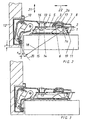
- the furniture hinge comprises a mounting plate, consisting of a base plate 1 and a setting plate 2, wherein the base plate 1 is fixed to the side wall of the furniture box 11.
- the adjusting plate 2 can be locked and releasably connected to the base plate 1.
- On the adjusting plate 2 of the hinge arm 8 is fixed, which articulated with a door-side stop member, for. B. a hinge cup 10, is connected, which is embedded in the furniture door 12 via screws 9.
- a conventional lateral adjustment screw 13 is provided for lateral adjustment of the furniture door 12, d. H. for adjusting the hinge arm 8 in the direction of the mounting plane or base plate 1, a conventional lateral adjustment screw 13 is provided.
- the depth adjustment ie the adjustment of the hinge arm 8 parallel to the base plate 1, by means of a depth adjustment screw 17, which has no thread as in the prior art, but is taken with its screw neck in an opening in the hinge arm 8 and is rotatably mounted there but not displaceable ,
- the depth adjustment screw 17 engages with its control part 23, which has an axially upper 24 and lower eccentric disk 25, in a recess 6 in the adjusting plate 2.
- the axially upper eccentric disc 24 lies with its angular, cassette-shaped footprint 26 at one L-shaped nose 3, which nose 3 was integrally formed from the adjusting plate 2, or is attached thereto.
- the lower eccentric disc 25 rests with its angular, cassette-shaped footprint 27 on the inner edge of the recess 6 of the adjusting plate 2.
- the nose 3 and the inner edge of the recess 6 are not in a common plane, wherein the nose 3 protrudes from the surface of the adjusting plate 2 in the direction of the hinge arm 8.
- Both shelves 26 and 27 are approximately frusto-conical and axially mirror-inverted to the longitudinal axis of the depth adjustment screw 17, so that the upper shelf 26 to the neck 31 and head 29 of the screw 17 tapers, the lower shelf 27 but directed away from the neck 31 and head 29 away tapers.
- the contact surface 3a of the nose 3 and the contact surface 7a of the edge 7 of the opening 6 of the adjusting plate 2 for cooperation with the shelves 26 and 27 are suitably made conical, so that favorable sliding surfaces are provided for sliding on each other and thus almost no material abrasion he follows.
- the two axes of symmetry of the eccentric discs 24, 25 and their shelves 26, 27 are arranged radially offset from each other and to the longitudinal axis of the screw 17, so that each eccentricity.
- Both eccentric discs 24, 25 are thus formed slightly eccentric to the longitudinal axis of the screw 17, so that the adjusting surfaces 26, 27 move radially upon rotation of the screw 17 via a tool in the opening 30, whereby the depth adjustment of the door 12 takes place.
- the stop surface 28 of the screw 17 prevents over-rotation of the screw 17 by contact with the adjusting plate 2 in the maximum position.
- the stop surface may be arranged instead of or in addition to the upper eccentric disc 24 and also a further stop surface for over-rotation of the screw 17 may be provided in the opposite direction, so that both directions of rotation are secured.
- the screw 17 is formed either at least between the neck 31 and the eccentric discs 24, 25 divisible, so that insertion into the recess in the hinge arm is possible, or this opening is formed as a slot and is slightly longer than the diameter of the head 29 of Screw 17.
- the screw 17 can be threaded there, so that then the contact surface 3a of the nose 3 on the surface 26 and the contact surface 7a of the opening edge 7 rests on the surface 27, and the bottom of the nose 3 on the formed between the eccentric discs 24, 25 flat support surface 32, whereby the control part 23 is easily clamped in the adjusting plate 2.
- the hinge arm 8 can be displaced in the direction of the arrow 22 until the gap S has the desired value, which is e.g. is preset to 2.5 mm. Thus, a slight and sensitive depth adjustment can be achieved.
- the side adjustment screw 13 is mounted with its thread 16 in a threaded bore of the hinge arm 8 and is supported with its screw head 14 on an associated contact surface 15 of the adjusting plate 2 from.
- the hinge arm 8 can now be adjusted in the direction of arrow 21, so that the door 12, for example, from the position to FIG. 1 in the position after FIG. 2 pivoted and the gap F changes.
- the hinge arm 8 is thus displaced by turning the side adjustment screw 13 and pivoting the hinge arm 8 about the pivot point 19 by an amount K in the depth in the direction 22, so that the gap S changes.
- the hinge arm 8 is displaced in the opposite direction 22 preferably by the same amount K (but negative), so that by the control part 23 of the depth adjustment screw 17 in the most favorable case a compensation of the depth shift to the Berag K. takes place and the gap S remains constant at the preset value (eg 2.5 mm).
- the depth adjustment thus has a special depth adjustment screw 17, the in FIG. 4 is shown in more detail.
- the depth adjustment screw 17 comprises two superimposed eccentric discs 24 and 25 which cooperate with arranged in the actuator plate 2 bearing surfaces.
- the adjusting plate 2 has a special opening 6 with opening edge 7 and one of the adjusting plate. 2 stepped nose 3, which contact surfaces for cooperation with the upper and lower eccentric disc 24, 25 form.
- the essence of the invention is therefore that in the adjustment of the soeinstellschraube 13, in addition to the desired lateral adjustment in the direction of arrow 21 by the amount F also to an undesirable change in the gap width in the direction of the arrow 22 by the amount K between the door 12 and the Carcass 11 leads, a compensation device is used.
- the compensation device consists of two non-rotatably connected to the depth adjustment screw 17 obliquely opposed sliding surfaces 26, 27 of two eccentric discs 24, 25 of a control member 23, which juxtaposed sliding surfaces 26, 27 abut against associated, fixed surfaces 3a, 7a of the adjusting plate 2.
Landscapes
- Engineering & Computer Science (AREA)
- Mechanical Engineering (AREA)
- Hinges (AREA)
Claims (8)
- Charnière de meuble avec un bras de charnière (8), une plaque de montage (1, 2) et un dispositif de réglage pour le bras de charnière (8) qui est monté directement ou indirectement sur la plaque de montage (1, 2) située côté meuble et composées d'une plaque de base (1) et d'une plaque de positionnement (2), et qui est relié de manière articulée à un élément de fixation (10) situé côté porte, le dispositif de réglage comportant une vis de réglage latéral (13) à l'aide de laquelle la position du bras de charnière (8) peut être modifiée globalement perpendiculairement au plan de la plaque de montage (1, 2) en vue d'un réglage latéral de la porte (12), et une vis de réglage de profondeur (17) à l'aide de laquelle la position du bras de charnière (8) peut être modifiée parallèlement à l'extension longitudinale de la plaque de montage (1, 2) en vue du réglage de profondeur de la porte (12), et présentant une fonction de compensation, une rotation de la vis de réglage latéral (13) provoquant ainsi un réglage latéral suivant une valeur (F) et en même temps un déplacement du bras de charnière (8) à peu près dans le sens de l'axe longitudinal de celui-ci par rapport à la plaque de montage (1, 2) et, ainsi, une correction du réglage de profondeur de la porte (12) suivant une valeur (K), de sorte qu'une largeur d'interstice (S) entre la porte (12) et la paroi latérale de meuble (11), une fois que le réglage latéral est effectué, reste globalement inchangée, caractérisée en ce que la vis de réglage de profondeur (17) est montée directement ou indirectement, en rotation et fixe en translation, sur le bras de charnière (8) et comporte un élément de commande (23) avec deux disques d'excentrique (24, 25) superposés axialement et pourvus de surfaces de positionnement tronconiques (26, 27) en miroir, ou avec un disque en spirale ou en hélice avec au moins une surface de positionnement (26, 27) au moins en partie tronconique ou concave ou convexe, la ou les surfaces de positionnement (26, 27) s'appuyant contre des surfaces d'appui associées (3, 7) de la plaque de montage (1, 2), la plaque de positionnement (2) présentant au bord (7) d'une ouverture (6) pour la vis de réglage de profondeur (17) une première surface d'appui (7a) et une saillie (3) décalée par rapport à l'ouverture (6) et pourvue d'une surface d'appui (3a), ce qui donne des surfaces d'appui (3a, 7a) superposées dans deux plans, pour le coulissement conjoint sur la ou la surfaces de positionnement (26, 27) et crée ainsi la fonction de compensation.
- Charnière de meuble selon la revendication 1, caractérisée en ce que la ou les surfaces de positionnement (26, 27) ne s'étendent pas sur toute la circonférence de 360°.
- Charnière de meuble selon la revendication 2, caractérisée en ce que l'axe de symétrie de la ou des surfaces de positionnement (26, 27) sont espacées de l'axe de rotation de la vis de réglage de profondeur (17), à peu près parallèlement à celui-ci.
- Charnière de meuble selon l'une des revendications 1 à 3, caractérisée en ce que les deux axes de symétrie, au moins, des disques d'excentrique (24, 25) sont espacés de l'axe de rotation de la vis de réglage de profondeur (17), à peu près parallèlement à celui-ci, et sont espacés l'un de l'autre à peu près parallèlement l'un à l'autre.
- Charnière de meuble selon l'une des revendications 3 ou 4, caractérisée en ce que le disque d'excentrique axialement inférieur (25) qui se trouve à l'extrémité libre de la vis de réglage de profondeur (17) va en s'effilant vers son extrémité libre tandis que le disque d'excentrique supérieur (24) qui se trouve au niveau de la tête de vis (29) va en s'effilant dans le sens opposé.
- Charnière de meuble selon l'une des revendications 1 à 5, caractérisée en ce que la vis de réglage de profondeur (17) a des surfaces de butée (28) pour limiter l'angle de rotation.
- Charnière de meuble selon la revendication 6, caractérisée en ce que les surfaces de butée (28) servent à s'appliquer contre la plaque de positionnement (2).
- Charnière de meuble selon l'une des revendications 1 à 7, caractérisée en ce que la vis de réglage de profondeur (17) a un collet (31) à symétrie de révolution qui traverse un creux du bras de charnière (8) et qui est logé dans celui-ci en rotation mais fixe en translation.
Applications Claiming Priority (2)
| Application Number | Priority Date | Filing Date | Title |
|---|---|---|---|
| DE10210017 | 2002-03-07 | ||
| DE10210017A DE10210017C1 (de) | 2002-03-07 | 2002-03-07 | Möbelscharnier mit Verstelleinrichtung |
Publications (3)
| Publication Number | Publication Date |
|---|---|
| EP1342874A2 EP1342874A2 (fr) | 2003-09-10 |
| EP1342874A3 EP1342874A3 (fr) | 2006-03-08 |
| EP1342874B1 true EP1342874B1 (fr) | 2009-10-07 |
Family
ID=7714039
Family Applications (1)
| Application Number | Title | Priority Date | Filing Date |
|---|---|---|---|
| EP03004625A Expired - Lifetime EP1342874B1 (fr) | 2002-03-07 | 2003-03-03 | Charnière de meuble avec dispositif de réglage |
Country Status (4)
| Country | Link |
|---|---|
| US (1) | US6925682B2 (fr) |
| EP (1) | EP1342874B1 (fr) |
| AT (1) | ATE445072T1 (fr) |
| DE (2) | DE10210017C1 (fr) |
Families Citing this family (13)
| Publication number | Priority date | Publication date | Assignee | Title |
|---|---|---|---|---|
| US6883204B2 (en) * | 2002-05-29 | 2005-04-26 | Arturo Salice S.P.A. | Hinge |
| DE102004041300A1 (de) * | 2004-08-25 | 2006-03-02 | Lautenschläger, Horst | Verstelleinrichtung für Möbelteile |
| AT501396B1 (de) * | 2004-10-28 | 2007-10-15 | Blum Gmbh Julius | Falttürenscharnier |
| JP5346579B2 (ja) * | 2005-04-29 | 2013-11-20 | プレメタ ゲゼルシャフト ミット ベシュレンクター ハフツング ウント コンパニー コマンディートゲゼルシャフト | ヒンジ |
| DE102006034306A1 (de) * | 2006-07-21 | 2008-01-24 | Liberty Hardware Mfg. Corp. | Möbelscharnier |
| DE202008012170U1 (de) * | 2008-04-18 | 2009-09-03 | Paul Hettich Gmbh & Co. Kg | Verstellvorrichtung für Möbel |
| US9074404B2 (en) | 2012-05-30 | 2015-07-07 | Bsh Home Applicances Corporation | Household appliance having system for aligning doors and method thereof |
| CN104879006B (zh) * | 2015-05-14 | 2017-10-17 | 陈明开 | 一种柜门铰链的改良结构 |
| US11261631B2 (en) * | 2017-05-11 | 2022-03-01 | Samet Kalip Ve Maden Esya San. Ve Tic. A.S. | Hinge having pinch protection and method for displacing securing parts of a hinge |
| TWI657184B (zh) * | 2017-06-19 | 2019-04-21 | 日商世嘉智尼工業股份有限公司 | 鉸鏈裝置 |
| AT523441B1 (de) * | 2020-01-17 | 2023-05-15 | Blum Gmbh Julius | Scharnieranordnung |
| AT526748B1 (de) * | 2022-11-21 | 2025-04-15 | Blum Gmbh Julius | Möbelbeschlag oder Baubeschlag |
| CN117722096B (zh) * | 2024-02-07 | 2024-04-19 | 广东图特精密五金科技股份有限公司 | 一种快速连接锁紧机构以及快装铰链 |
Family Cites Families (32)
| Publication number | Priority date | Publication date | Assignee | Title |
|---|---|---|---|---|
| US1336174A (en) * | 1919-09-23 | 1920-04-06 | Way John Howard | Concealed or invisible butt-hinge |
| FR2421594A1 (fr) * | 1977-06-20 | 1979-11-02 | Micro Mega Sa | Tete de contre-angle pour piece a main dentaire |
| DE3209900A1 (de) * | 1982-03-18 | 1983-09-22 | Karl Lautenschläger KG, Möbelbeschlagfabrik, 6107 Reinheim | Kreuzgelenkscharnier |
| AT379851B (de) * | 1983-03-21 | 1986-03-10 | Blum Gmbh Julius | Scharnier, insbesondere fuer moebeltueren |
| DE3448346C2 (fr) * | 1983-12-30 | 1990-12-13 | Julius Blum Ges.M.B.H., Hoechst, At | |
| AT383643B (de) * | 1984-10-19 | 1987-07-27 | Blum Gmbh Julius | Scharnier |
| AT384066B (de) * | 1984-10-19 | 1987-09-25 | Blum Gmbh Julius | Scharnier |
| AT391344B (de) * | 1987-08-31 | 1990-09-25 | Blum Gmbh Julius | Scharnier |
| DE3820338A1 (de) * | 1988-06-15 | 1989-12-21 | Lautenschlaeger Kg Karl | Moebelscharnier |
| DE3841405A1 (de) * | 1988-06-29 | 1990-01-04 | Salice Arturo Spa | Scharnierarm mit einer befestigungsplatte zu dessen befestigung an einem moebelteil o. dgl. |
| DE68914595T2 (de) * | 1988-11-16 | 1994-08-25 | Franco Ferrari | Türscharnier mit Schnellkupplung. |
| DE4009125A1 (de) * | 1989-05-19 | 1991-09-26 | Salice Arturo Spa | Scharnier, vorzugsweise zur anlenkung einer tuer oder klappe an eine tragwand eines korpusteils |
| DE8907480U1 (de) * | 1989-06-20 | 1989-08-03 | Karl Lautenschlaeger Gmbh & Co Kg Moebelbeschlagfabrik, 6107 Reinheim | Montageplatte für Möbelscharniere |
| EP0460233B1 (fr) * | 1989-12-25 | 1994-09-28 | Kabushiki Kaisha Murakoshi Seiko | Charniere de fixation amovible pour porte de meuble ou similaire |
| DE3943210C1 (fr) * | 1989-12-28 | 1991-06-20 | Arturo Salice S.P.A., Novedrate, Como, It | |
| JP2551740Y2 (ja) * | 1991-10-09 | 1997-10-27 | 株式会社太田製作所 | スライドヒンジ |
| DE4211722A1 (de) * | 1992-04-08 | 1993-10-14 | Lautenschlaeger Mepla Werke | Möbelscharnier |
| AT404858B (de) * | 1993-10-25 | 1999-03-25 | Lautenschlaeger Mepla Werke | Als scharniertopf ausgebildeter tür-anschlagteil für möbelscharniere |
| DE4342744A1 (de) * | 1993-12-15 | 1995-06-22 | Lautenschlaeger Mepla Werke | Möbelscharnier |
| AT1214U1 (de) * | 1995-12-18 | 1996-12-27 | Blum Gmbh Julius | Scharnier |
| IT1282620B1 (it) * | 1996-02-14 | 1998-03-31 | Franco Ferrari | Dispositivo di regolazione a camma per elementi di ferramenta per mobili ed elementi di ferramenta con esso |
| AT1787U1 (de) * | 1996-08-21 | 1997-11-25 | Blum Gmbh Julius | Scharnier für möbel |
| US5964011A (en) * | 1997-09-12 | 1999-10-12 | Newell Operating Company | Adjustable casement window hinge |
| US6061872A (en) * | 1998-03-02 | 2000-05-16 | Grass Gmbh | Cabinet hinge |
| EP0967353A1 (fr) * | 1998-06-26 | 1999-12-29 | Charmag S.A. | Charnière |
| DE29811793U1 (de) | 1998-07-02 | 1999-11-18 | Mepla-Werke Lautenschläger GmbH & Co KG, 64354 Reinheim | Möbelscharnier |
| EP0982455B1 (fr) * | 1998-08-25 | 2005-01-26 | Julius Blum GmbH | Charnière de meuble |
| DE29914473U1 (de) * | 1998-08-25 | 2000-01-05 | Julius Blum Ges.m.b.H., Höchst | Scharnier |
| US6268848B1 (en) * | 1998-10-23 | 2001-07-31 | Genesis Microchip Corp. | Method and apparatus implemented in an automatic sampling phase control system for digital monitors |
| DE19920137C2 (de) * | 1999-05-03 | 2002-11-28 | Grass Gmbh Hoechst | Montageplatte für Möbelscharniere |
| DE10054238B4 (de) * | 2000-11-02 | 2005-07-21 | Grass Gmbh | Möbelscharnier |
| EP1288416B1 (fr) * | 2001-08-31 | 2009-12-30 | Grass GmbH | Charnière de meuble |
-
2002
- 2002-03-07 DE DE10210017A patent/DE10210017C1/de not_active Expired - Fee Related
-
2003
- 2003-03-03 DE DE50311990T patent/DE50311990D1/de not_active Expired - Lifetime
- 2003-03-03 AT AT03004625T patent/ATE445072T1/de active
- 2003-03-03 EP EP03004625A patent/EP1342874B1/fr not_active Expired - Lifetime
- 2003-03-04 US US10/379,066 patent/US6925682B2/en not_active Expired - Fee Related
Also Published As
| Publication number | Publication date |
|---|---|
| DE50311990D1 (de) | 2009-11-19 |
| ATE445072T1 (de) | 2009-10-15 |
| DE10210017C1 (de) | 2003-07-31 |
| US20040034965A1 (en) | 2004-02-26 |
| EP1342874A3 (fr) | 2006-03-08 |
| EP1342874A2 (fr) | 2003-09-10 |
| US6925682B2 (en) | 2005-08-09 |
Similar Documents
| Publication | Publication Date | Title |
|---|---|---|
| DE10054238B4 (de) | Möbelscharnier | |
| DE102007056266B4 (de) | Presse | |
| DE10210017C1 (de) | Möbelscharnier mit Verstelleinrichtung | |
| EP2265784B1 (fr) | Dispositif de réglage pour meubles | |
| EP3029238B1 (fr) | Ferrure d'angle dotée d'une plage de serrage réglable | |
| AT409288B (de) | Möbelscharnier | |
| EP1653031B1 (fr) | Charnière de porte pliante | |
| DE10110311C2 (de) | Scharnier mit Höhenverstellschraube | |
| AT406497B (de) | Scharnier | |
| WO1990014573A1 (fr) | Porte-comparateur reglable pour l'ajustage de precision d'un comparateur a cadran | |
| DE2949962C2 (de) | Scharnier mit Schließmechanismus | |
| DE2420371A1 (de) | Verstellbarer ringschluessel | |
| EP0702386A1 (fr) | Actionneur pivotable pour un interrupteur de sécurité | |
| EP1288415A1 (fr) | Charnière de meuble | |
| EP3029235B1 (fr) | Ferrure d'angle destinée à l'agencement d'un élément de porte sur un pivot ou un axe | |
| AT390471B (de) | Moebelscharnier mit einer seiten- und tiefeneinstelleinrichtung | |
| EP0403863B1 (fr) | Charnière de meuble | |
| DE29713254U1 (de) | Drehlager für Fenster oder Türen | |
| AT518048B1 (de) | Schubladenwand | |
| EP1617025B1 (fr) | Charnière pour portes à fermeture bout à bout | |
| EP1223275B1 (fr) | Penture pour portes ou fenêtres | |
| AT526953B1 (de) | Führungsanordnung zur Führung eines bewegbaren Möbelteils | |
| EP0188613A1 (fr) | Systeme a bras oscillants | |
| EP1720428A1 (fr) | Dispositif de reglage pour ferrures de meubles | |
| AT526950B1 (de) | Führungsanordnung zur Führung eines bewegbaren Möbelteils |
Legal Events
| Date | Code | Title | Description |
|---|---|---|---|
| PUAI | Public reference made under article 153(3) epc to a published international application that has entered the european phase |
Free format text: ORIGINAL CODE: 0009012 |
|
| AK | Designated contracting states |
Kind code of ref document: A2 Designated state(s): AT BE BG CH CY CZ DE DK EE ES FI FR GB GR HU IE IT LI LU MC NL PT SE SI SK TR |
|
| AX | Request for extension of the european patent |
Extension state: AL LT LV MK RO |
|
| RIN1 | Information on inventor provided before grant (corrected) |
Inventor name: MUELLER, WOLFGANG Inventor name: ALBRECHT, MARKUS |
|
| PUAL | Search report despatched |
Free format text: ORIGINAL CODE: 0009013 |
|
| AK | Designated contracting states |
Kind code of ref document: A3 Designated state(s): AT BE BG CH CY CZ DE DK EE ES FI FR GB GR HU IE IT LI LU MC NL PT SE SI SK TR |
|
| AX | Request for extension of the european patent |
Extension state: AL LT LV MK RO |
|
| 17P | Request for examination filed |
Effective date: 20060330 |
|
| AKX | Designation fees paid |
Designated state(s): AT BE BG CH CY CZ DE DK EE ES FI FR GB GR HU IE IT LI LU MC NL PT SE SI SK TR |
|
| 17Q | First examination report despatched |
Effective date: 20081209 |
|
| GRAP | Despatch of communication of intention to grant a patent |
Free format text: ORIGINAL CODE: EPIDOSNIGR1 |
|
| GRAC | Information related to communication of intention to grant a patent modified |
Free format text: ORIGINAL CODE: EPIDOSCIGR1 |
|
| GRAS | Grant fee paid |
Free format text: ORIGINAL CODE: EPIDOSNIGR3 |
|
| GRAA | (expected) grant |
Free format text: ORIGINAL CODE: 0009210 |
|
| AK | Designated contracting states |
Kind code of ref document: B1 Designated state(s): AT BE BG CH CY CZ DE DK EE ES FI FR GB GR HU IE IT LI LU MC NL PT SE SI SK TR |
|
| REG | Reference to a national code |
Ref country code: GB Ref legal event code: FG4D Free format text: NOT ENGLISH |
|
| REG | Reference to a national code |
Ref country code: CH Ref legal event code: EP |
|
| REG | Reference to a national code |
Ref country code: IE Ref legal event code: FG4D |
|
| REF | Corresponds to: |
Ref document number: 50311990 Country of ref document: DE Date of ref document: 20091119 Kind code of ref document: P |
|
| PG25 | Lapsed in a contracting state [announced via postgrant information from national office to epo] |
Ref country code: SI Free format text: LAPSE BECAUSE OF FAILURE TO SUBMIT A TRANSLATION OF THE DESCRIPTION OR TO PAY THE FEE WITHIN THE PRESCRIBED TIME-LIMIT Effective date: 20091007 |
|
| NLV1 | Nl: lapsed or annulled due to failure to fulfill the requirements of art. 29p and 29m of the patents act | ||
| PG25 | Lapsed in a contracting state [announced via postgrant information from national office to epo] |
Ref country code: ES Free format text: LAPSE BECAUSE OF FAILURE TO SUBMIT A TRANSLATION OF THE DESCRIPTION OR TO PAY THE FEE WITHIN THE PRESCRIBED TIME-LIMIT Effective date: 20100118 Ref country code: SE Free format text: LAPSE BECAUSE OF FAILURE TO SUBMIT A TRANSLATION OF THE DESCRIPTION OR TO PAY THE FEE WITHIN THE PRESCRIBED TIME-LIMIT Effective date: 20091007 Ref country code: FI Free format text: LAPSE BECAUSE OF FAILURE TO SUBMIT A TRANSLATION OF THE DESCRIPTION OR TO PAY THE FEE WITHIN THE PRESCRIBED TIME-LIMIT Effective date: 20091007 Ref country code: PT Free format text: LAPSE BECAUSE OF FAILURE TO SUBMIT A TRANSLATION OF THE DESCRIPTION OR TO PAY THE FEE WITHIN THE PRESCRIBED TIME-LIMIT Effective date: 20100208 |
|
| REG | Reference to a national code |
Ref country code: IE Ref legal event code: FD4D |
|
| PG25 | Lapsed in a contracting state [announced via postgrant information from national office to epo] |
Ref country code: NL Free format text: LAPSE BECAUSE OF FAILURE TO SUBMIT A TRANSLATION OF THE DESCRIPTION OR TO PAY THE FEE WITHIN THE PRESCRIBED TIME-LIMIT Effective date: 20091007 Ref country code: BG Free format text: LAPSE BECAUSE OF FAILURE TO SUBMIT A TRANSLATION OF THE DESCRIPTION OR TO PAY THE FEE WITHIN THE PRESCRIBED TIME-LIMIT Effective date: 20100107 Ref country code: DK Free format text: LAPSE BECAUSE OF FAILURE TO SUBMIT A TRANSLATION OF THE DESCRIPTION OR TO PAY THE FEE WITHIN THE PRESCRIBED TIME-LIMIT Effective date: 20091007 Ref country code: IE Free format text: LAPSE BECAUSE OF FAILURE TO SUBMIT A TRANSLATION OF THE DESCRIPTION OR TO PAY THE FEE WITHIN THE PRESCRIBED TIME-LIMIT Effective date: 20091007 Ref country code: EE Free format text: LAPSE BECAUSE OF FAILURE TO SUBMIT A TRANSLATION OF THE DESCRIPTION OR TO PAY THE FEE WITHIN THE PRESCRIBED TIME-LIMIT Effective date: 20091007 |
|
| PLBE | No opposition filed within time limit |
Free format text: ORIGINAL CODE: 0009261 |
|
| STAA | Information on the status of an ep patent application or granted ep patent |
Free format text: STATUS: NO OPPOSITION FILED WITHIN TIME LIMIT |
|
| PG25 | Lapsed in a contracting state [announced via postgrant information from national office to epo] |
Ref country code: CZ Free format text: LAPSE BECAUSE OF FAILURE TO SUBMIT A TRANSLATION OF THE DESCRIPTION OR TO PAY THE FEE WITHIN THE PRESCRIBED TIME-LIMIT Effective date: 20091007 Ref country code: SK Free format text: LAPSE BECAUSE OF FAILURE TO SUBMIT A TRANSLATION OF THE DESCRIPTION OR TO PAY THE FEE WITHIN THE PRESCRIBED TIME-LIMIT Effective date: 20091007 |
|
| 26N | No opposition filed |
Effective date: 20100708 |
|
| BERE | Be: lapsed |
Owner name: GRASS GMBH Effective date: 20100331 |
|
| PG25 | Lapsed in a contracting state [announced via postgrant information from national office to epo] |
Ref country code: GR Free format text: LAPSE BECAUSE OF FAILURE TO SUBMIT A TRANSLATION OF THE DESCRIPTION OR TO PAY THE FEE WITHIN THE PRESCRIBED TIME-LIMIT Effective date: 20100108 Ref country code: MC Free format text: LAPSE BECAUSE OF NON-PAYMENT OF DUE FEES Effective date: 20100331 |
|
| REG | Reference to a national code |
Ref country code: CH Ref legal event code: PL |
|
| GBPC | Gb: european patent ceased through non-payment of renewal fee |
Effective date: 20100303 |
|
| REG | Reference to a national code |
Ref country code: FR Ref legal event code: ST Effective date: 20101130 |
|
| PG25 | Lapsed in a contracting state [announced via postgrant information from national office to epo] |
Ref country code: FR Free format text: LAPSE BECAUSE OF NON-PAYMENT OF DUE FEES Effective date: 20100331 |
|
| PG25 | Lapsed in a contracting state [announced via postgrant information from national office to epo] |
Ref country code: CH Free format text: LAPSE BECAUSE OF NON-PAYMENT OF DUE FEES Effective date: 20100331 Ref country code: BE Free format text: LAPSE BECAUSE OF NON-PAYMENT OF DUE FEES Effective date: 20100331 Ref country code: LI Free format text: LAPSE BECAUSE OF NON-PAYMENT OF DUE FEES Effective date: 20100331 |
|
| PG25 | Lapsed in a contracting state [announced via postgrant information from national office to epo] |
Ref country code: GB Free format text: LAPSE BECAUSE OF NON-PAYMENT OF DUE FEES Effective date: 20100303 |
|
| PGFP | Annual fee paid to national office [announced via postgrant information from national office to epo] |
Ref country code: DE Payment date: 20120308 Year of fee payment: 10 |
|
| PGFP | Annual fee paid to national office [announced via postgrant information from national office to epo] |
Ref country code: IT Payment date: 20120227 Year of fee payment: 10 |
|
| PG25 | Lapsed in a contracting state [announced via postgrant information from national office to epo] |
Ref country code: CY Free format text: LAPSE BECAUSE OF FAILURE TO SUBMIT A TRANSLATION OF THE DESCRIPTION OR TO PAY THE FEE WITHIN THE PRESCRIBED TIME-LIMIT Effective date: 20091007 |
|
| PG25 | Lapsed in a contracting state [announced via postgrant information from national office to epo] |
Ref country code: HU Free format text: LAPSE BECAUSE OF FAILURE TO SUBMIT A TRANSLATION OF THE DESCRIPTION OR TO PAY THE FEE WITHIN THE PRESCRIBED TIME-LIMIT Effective date: 20100408 Ref country code: LU Free format text: LAPSE BECAUSE OF NON-PAYMENT OF DUE FEES Effective date: 20100303 |
|
| PG25 | Lapsed in a contracting state [announced via postgrant information from national office to epo] |
Ref country code: TR Free format text: LAPSE BECAUSE OF FAILURE TO SUBMIT A TRANSLATION OF THE DESCRIPTION OR TO PAY THE FEE WITHIN THE PRESCRIBED TIME-LIMIT Effective date: 20091007 |
|
| PGFP | Annual fee paid to national office [announced via postgrant information from national office to epo] |
Ref country code: AT Payment date: 20120524 Year of fee payment: 10 |
|
| REG | Reference to a national code |
Ref country code: AT Ref legal event code: MM01 Ref document number: 445072 Country of ref document: AT Kind code of ref document: T Effective date: 20130303 |
|
| REG | Reference to a national code |
Ref country code: DE Ref legal event code: R119 Ref document number: 50311990 Country of ref document: DE Effective date: 20131001 |
|
| PG25 | Lapsed in a contracting state [announced via postgrant information from national office to epo] |
Ref country code: AT Free format text: LAPSE BECAUSE OF NON-PAYMENT OF DUE FEES Effective date: 20130303 Ref country code: DE Free format text: LAPSE BECAUSE OF NON-PAYMENT OF DUE FEES Effective date: 20131001 |
|
| PG25 | Lapsed in a contracting state [announced via postgrant information from national office to epo] |
Ref country code: IT Free format text: LAPSE BECAUSE OF NON-PAYMENT OF DUE FEES Effective date: 20130303 |