EP1342900A2 - Abschaltsteuerung einer Brennkraftmachine - Google Patents
Abschaltsteuerung einer Brennkraftmachine Download PDFInfo
- Publication number
- EP1342900A2 EP1342900A2 EP03005003A EP03005003A EP1342900A2 EP 1342900 A2 EP1342900 A2 EP 1342900A2 EP 03005003 A EP03005003 A EP 03005003A EP 03005003 A EP03005003 A EP 03005003A EP 1342900 A2 EP1342900 A2 EP 1342900A2
- Authority
- EP
- European Patent Office
- Prior art keywords
- internal combustion
- combustion engine
- exhaust gas
- amount
- fuel injection
- Prior art date
- Legal status (The legal status is an assumption and is not a legal conclusion. Google has not performed a legal analysis and makes no representation as to the accuracy of the status listed.)
- Withdrawn
Links
- 238000002485 combustion reaction Methods 0.000 title claims abstract description 110
- 239000000446 fuel Substances 0.000 claims abstract description 102
- 238000002347 injection Methods 0.000 claims abstract description 70
- 239000007924 injection Substances 0.000 claims abstract description 70
- 239000007789 gas Substances 0.000 description 52
- 230000006835 compression Effects 0.000 description 24
- 238000007906 compression Methods 0.000 description 24
- 239000007858 starting material Substances 0.000 description 4
- 230000003247 decreasing effect Effects 0.000 description 3
- 230000001133 acceleration Effects 0.000 description 2
- 238000001816 cooling Methods 0.000 description 2
- 238000010586 diagram Methods 0.000 description 2
- XLYOFNOQVPJJNP-UHFFFAOYSA-N water Substances O XLYOFNOQVPJJNP-UHFFFAOYSA-N 0.000 description 2
- 238000004378 air conditioning Methods 0.000 description 1
- 238000013459 approach Methods 0.000 description 1
- QVGXLLKOCUKJST-UHFFFAOYSA-N atomic oxygen Chemical compound [O] QVGXLLKOCUKJST-UHFFFAOYSA-N 0.000 description 1
- 239000003054 catalyst Substances 0.000 description 1
- 230000003197 catalytic effect Effects 0.000 description 1
- 238000004140 cleaning Methods 0.000 description 1
- 238000000034 method Methods 0.000 description 1
- 239000001301 oxygen Substances 0.000 description 1
- 229910052760 oxygen Inorganic materials 0.000 description 1
- 238000005086 pumping Methods 0.000 description 1
- 239000000779 smoke Substances 0.000 description 1
Images


Classifications
-
- F—MECHANICAL ENGINEERING; LIGHTING; HEATING; WEAPONS; BLASTING
- F02—COMBUSTION ENGINES; HOT-GAS OR COMBUSTION-PRODUCT ENGINE PLANTS
- F02D—CONTROLLING COMBUSTION ENGINES
- F02D41/00—Electrical control of supply of combustible mixture or its constituents
- F02D41/02—Circuit arrangements for generating control signals
- F02D41/04—Introducing corrections for particular operating conditions
- F02D41/042—Introducing corrections for particular operating conditions for stopping the engine
-
- F—MECHANICAL ENGINEERING; LIGHTING; HEATING; WEAPONS; BLASTING
- F02—COMBUSTION ENGINES; HOT-GAS OR COMBUSTION-PRODUCT ENGINE PLANTS
- F02D—CONTROLLING COMBUSTION ENGINES
- F02D41/00—Electrical control of supply of combustible mixture or its constituents
- F02D41/0002—Controlling intake air
-
- F—MECHANICAL ENGINEERING; LIGHTING; HEATING; WEAPONS; BLASTING
- F02—COMBUSTION ENGINES; HOT-GAS OR COMBUSTION-PRODUCT ENGINE PLANTS
- F02D—CONTROLLING COMBUSTION ENGINES
- F02D41/00—Electrical control of supply of combustible mixture or its constituents
- F02D41/0025—Controlling engines characterised by use of non-liquid fuels, pluralities of fuels, or non-fuel substances added to the combustible mixtures
- F02D41/0047—Controlling exhaust gas recirculation [EGR]
- F02D41/005—Controlling exhaust gas recirculation [EGR] according to engine operating conditions
- F02D41/0055—Special engine operating conditions, e.g. for regeneration of exhaust gas treatment apparatus
-
- F—MECHANICAL ENGINEERING; LIGHTING; HEATING; WEAPONS; BLASTING
- F02—COMBUSTION ENGINES; HOT-GAS OR COMBUSTION-PRODUCT ENGINE PLANTS
- F02D—CONTROLLING COMBUSTION ENGINES
- F02D41/00—Electrical control of supply of combustible mixture or its constituents
- F02D41/02—Circuit arrangements for generating control signals
- F02D41/04—Introducing corrections for particular operating conditions
- F02D41/06—Introducing corrections for particular operating conditions for engine starting or warming up
- F02D41/062—Introducing corrections for particular operating conditions for engine starting or warming up for starting
- F02D41/065—Introducing corrections for particular operating conditions for engine starting or warming up for starting at hot start or restart
-
- F—MECHANICAL ENGINEERING; LIGHTING; HEATING; WEAPONS; BLASTING
- F02—COMBUSTION ENGINES; HOT-GAS OR COMBUSTION-PRODUCT ENGINE PLANTS
- F02D—CONTROLLING COMBUSTION ENGINES
- F02D41/00—Electrical control of supply of combustible mixture or its constituents
- F02D41/009—Electrical control of supply of combustible mixture or its constituents using means for generating position or synchronisation signals
- F02D2041/0095—Synchronisation of the cylinders during engine shutdown
-
- Y—GENERAL TAGGING OF NEW TECHNOLOGICAL DEVELOPMENTS; GENERAL TAGGING OF CROSS-SECTIONAL TECHNOLOGIES SPANNING OVER SEVERAL SECTIONS OF THE IPC; TECHNICAL SUBJECTS COVERED BY FORMER USPC CROSS-REFERENCE ART COLLECTIONS [XRACs] AND DIGESTS
- Y02—TECHNOLOGIES OR APPLICATIONS FOR MITIGATION OR ADAPTATION AGAINST CLIMATE CHANGE
- Y02T—CLIMATE CHANGE MITIGATION TECHNOLOGIES RELATED TO TRANSPORTATION
- Y02T10/00—Road transport of goods or passengers
- Y02T10/10—Internal combustion engine [ICE] based vehicles
- Y02T10/40—Engine management systems
Definitions
- a control of a stop position (a crank angle at stopping a rotation angle position) of a crankshaft of the internal combustion engine is performed when the internal combustion engine is stopped.
- a stop position a crank angle at stopping a rotation angle position
- operation state of each cylinder is determined and then fuel is injected into a cylinder which is in the compression stroke.
- the stop position may be controlled by determining the operation state of cylinders immediately after the internal combustion engine has just been motored (cranked) for the subsequent restarting of the internal combustion engine.
- the invention disclosed in the publication has a structure in which a cylinder at the compression top dead center is identified based on the crank angle of the engine.
- the fuel supply stop is started with a predetermined cylinder which has been determined based on the cylinder determined as the one at the top dead center.
- the related art can determine a crank angle range where the engine stops by determining a cylinder with which the fuel supply stop is started. It is also mentioned in the publication, as a result, the related art can determine a cylinder more promptly by putting a mark for cylinder determination on a position closest to the crank angle range where the engine stops in the direction of the crankshaft rotation.
- the engine is controlled such that a crank angle position at which the engine is stopped is placed in a predetermined range since a fuel supply stop is started from the predetermined cylinder. More specifically, inertial energy of the engine is consumed as a friction loss, pumping loss or the like even when a fuel supply has been stopped. Then the engine finally stops.
- a crank angle range where the engine stops can be determined by determining a cylinder with which a fuel supply stop is started, because the number of revolution of the crankshaft after the fuel supply is stopped is substantially fixed.
- the engine can be Stopped in a predetermined crank angle range if a fuel supply stop is started with a predetermined cylinder.
- rotation to some extent is generated by inertial force even after a fuel supply has been completely stopped.
- just merely stopping a fuel supply may continuously generate a decreased output torque caused by a compressed intake air and an increased output torque subsequently caused by an expanded air.
- Such a torque fluctuation which is increased as intake air amount is increased, appears as vibration immediately before the engine is stopped, and thus causes the occupants to feel uncomfortable.
- a diesel engine having high compression ratio may cause more remarkable vibration due to the fluctuation of output torque if an intake air amount immediately after the fuel supply is stopped is relatively large.
- a recent internal combustion engine has an exhaust gas circulation system for reducing NOx.
- an internal combustion engine of this type circulated exhaust gas together with air is sucked into the cylinder.
- the intake air amount after a fuel supply is stopped increases as mentioned above which may cause vibration immediately after the internal combustion engine is stopped.
- stopping exhaust gas circulation when a stop control of internal combustion engine has been started can be conceived.
- the oxygen amount in the cylinder increases and thus fuel combustion is accelerated.
- Combustion noise i.e. so-called diesel knock, caused by rapid combustion is generated, and it may make the occupants feel uncomfortable.
- the air intake controlling means is provided with intake air amount adjusting means capable of adjusting intake air amount sucked into the internal combustion engine. Furthermore, the air intake controlling means executes a control so as to interrupt air intake after the last fuel injection. Moreover, the internal combustion engine automatically stops if a predetermined braking condition is established, and automatically restarts if the predetermined braking condition is released. The air intake controlling means executes control of the intake air amount during a time from when the predetermined braking condition is established and until when the internal combustion engine automatically stops.
- the intake air amount controlling means is an intake valve which controls an intake air amount by opening and closing. Furthermore, the air intake controlling means controls the intake valve such that it has a predetermined opening at a predetermined timing.
- the predetermined opening is such a predetermined value such that the intake air amount is smaller than the amount for idling state and not causing a misfire. Furthermore, the predetermined opening is a value that changes according to fuel injection amount or temperature of the internal combustion engine. Furthermore, the predetermined timing is determined based on the opening of the intake valve and on the speed of opening and closing of the intake valve immediately before the intake air amount is controlled by the controlling means.
- the invention is a stop controller for a internal combustion engine for controlling fuel injection such that the engine is stopped at a predetermined rotation angle position.
- the stop controller is provided with an exhaust gas circulation mechanism for circulating part of exhaust gas into the intake air side.
- the stop controller is provided further with exhaust gas controlling means for controlling exhaust gas amount circulated in the exhaust gas circulation system at a last fuel injection timing so as to make it smaller than an amount circulated before the last fuel injection.
- the exhaust gas controlling means controls the exhaust valve such that it has a predetermined opening at a predetermined timing.
- the predetermined opening is a value predetermined such that the circulated exhaust gas amount is smaller than a circulated amount before the last fuel injection.
- the predetermined opening is a value that changes according to fuel injection amount or temperature of the internal combustion engine.
- the predetermined timing is determined based on the opening of the exhaust valve and the speed of opening and closing of the exhaust valve immediately before they are controlled by the exhaust gas controlling means.
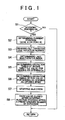
- FIG. 1 is a flowchart describing an example of control executed by a controller according to the invention
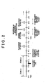
- FIG. 2 is a time chart shown in crank angle describing a stop timing of fuel injection according to a stop request
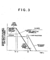
- FIG. 3 is a time chart showing fluctuations in the openings of the intake throttle valve and the EGR valve according to the invention, as well as fluctuations in the engine speed;
- FIG. 4 is a block diagram schematically showing the control system of the internal combustion engine according to the invention.
- FIG. 5 is a diagram schematically showing an example of fuel pump
- FIG. 6 is a schematic view showing an example of crank angle sensor
- FIG. 7 is a schematic view showing an example of crank angle datum position sensor.
- An internal combustion engine according to the invention is an internal combustion engine capable of stopping and restarting automatically by starting and stopping a supply of fuel and air, or by turning on and off the ignition or the like.
- Examples of such an internal combustion engine arc diesel engines, gasoline engines, and gas-fueled engines.
- FIG. 4 shows a diesel engine as an example of an internal combustion engine (engine) 1.
- the example shown in the figure is an engine of so-called direct injection type which directly injects fuel into cylinders 2, 3, 4, 5, provided with an exhaust gas re-circulation system (EGR) for cleaning exhaust gas.
- EGR exhaust gas re-circulation system
- the cylinders in FIG. 4 are referred to as #1 cylinder 2, #2 cylinder 3, #3 cylinder 4 and #4 cylinder 5, starting from the left most one.
- the cylinders reach the compression top dead center in the order of #1 cylinder 2, #3 cylinder 4, #4 Cylinder 5, and #2 cylinder 3.
- the cylinders 2, 3, 4 and 5 are provided with an injector 6, 7, 8 and 9, respectively, which is for injecting fuel under high pressure.
- the injectors 6, 7, 8 and 9 are connected to a common rail 10 for holding temporarily the fuel that has been pressurized to high pressure.
- the cylinders 2, 3, 4 and 5 are provided with a glow 11, 12, 13 and 14, respectively.
- a fuel pump 15 for pressurizing fuel is a so-called plunger type pump.
- the fuel pump 15 is pressurized by an elliptic cam 17 which rotates integrally with a cam shaft 16.
- the fuel pump 15 is designed so as to return by means of a return spring 18.
- the cam shaft 16 is designed so as to rotate one revolution while a crank shaft (not shown in the figure) rotates two revolutions.
- the elliptic cam 17 is designed so as to press a plunger with its both end portions of the longer axis direction. Therefore, intake and delivery of fuel by pressure are respectively executed once at every 360 degrees CA in crank angle degree (CA).
- CA crank angle degree
- an intake manifold 19 for supplying by allocating an intake air into each of the cylinders 2,3,4 and 5, is connected to a compressor 21 in an exhaust-type supercharger 20.
- the intake throttle valve 23 is electrically controlled by an actuator such as a motor (not shown in the figure).
- an exhaust manifold 24 connected to an exhaust port of each of the cylinders 2, 3, 4 and 5 is connected to an exhaust gas turbine 25 in the exhaust-type supercharger 20. Further, the exhaust gas turbine 25 is communicated with a catalytic converter 26 which is provided with an exhaust gas purifying catalyst.
- An EGR cooler 28 for cooling down exhaust gas and an EGR valve 29 for controlling the flow rate of exhaust gas are interposed in the exhaust gas re-circulation passage 27, in the order mentioned here from the one at the exhaust manifold 24 side.
- a starter 30 is provided as a rotation drive mechanism for executing this control. Any starter with an appropriate structure can be employed as the starter 30.
- an item can be employed having a structure where a pinion gear (not shown in the figure) is moved forward according to a start-up signal, and then the pinion gear is meshed (or engaged) with a ring gear (not shown in the figure) in the engine 1, thus the engine 1 is rotated under this condition.
- the aforementioned engine 1 is designed for which a so-called economy running control is executed.
- the economy running control automatically stops the engine 1 when a predetermined condition, such as a condition in which the vehicle is at a stop state and a braking operation, is established. And it automatically restarts the engine when that stopping condition is cancelled, such as a condition in which the braking operation is cancelled.
- a predetermined condition such as a condition in which the vehicle is at a stop state and a braking operation
- ECO-ECU electronic economy running control unit
- the electronic economy running control unit 32 is designed to execute a calculation based on the input and determine whether a stopping condition or restarting condition of the engine 1 is established.
- a stopping request or a restarting request of the engine 1 is output to the electronic engine control unit 31 according to the determination result.
- the stopping condition is, for example, a state where the vehicle speed is determined as zero and at the same time the braking operation is being executed.
- the starting condition is a state in which any of the stopping conditions becomes unsatisfied, for example, that the braking operation is released.
- the electronic engine control unit 31 executes control of stopping or starting of the engine 1, according to the request of stopping or starting the engine 1, when the request is issued. It is designed such that, if no such requests are issued, the output of the engine 1 (more specifically, the fuel injection amount) is controlled according to an amount of driving request which is represented by an accelezator opening.
- the crank angle sensor 34 is designed so as to be capable of detecting a rotation angle degree of the crank shaft as an angle from the aforementioned notched portion 38. If explained more specifically, according to an example of four-cycle engine having four cylinders, when the pistons of two of the cylinders (for example, where ignition occurs first and third) reach their top dead centers at the same time, it means one of them has reached at the top dead center in the compression stroke, and the other is at the top dead center in the exhaust stroke.
- a rotation angle of the crank shaft can be detected if a relative position of the notched portion 38 and the pickup 37 have been determined in advance so that their top dead centers are positioned at a predetermined angle (for example, at a 210-degree position) from the aforementioned notched portion 38.
- the crank angle datum position sensor 35 is designed so as to complete one revolution while the crank shaft rotates two revolutions.
- the sensor 35 provides a datum position of the angle for two revolutions of the crank shaft.
- one protrusion 40 is formed in the outer circumference portion of a rotational member 39, for example a cam shaft timing pulley, which rotates one revolution while the crank shaft rotates two revolutions.
- a pickup 41 for outputting a pulse signal responding to the protrusion 40 is provided in the outer circumference side of the rotation member 39.
- the relative positions of the protrusion 40 and the pickup 41 are placed at a position where the protrusion 40 is detected by the pickup 41 while the crank shaft rotates predetermined angle degrees (for example, 120 degrees) when the pickup 37 in the aforementioned crank angle sensor 34 has detected the notched portion 38.
- crank angle sensor 34 detects the aforementioned predetermined angle degrees (for example, 210 degrees) from the notched portion 38, each piston of the two cylinders is placed at each top dead center.
- the engine 1 determines a cylinder based on a signal (Signal Ne) from the crank angle sensor 34 and a signal (Signal G1) from the crank angle datum position sensor 35. Therefore, cylinder determination can be executed without fail if the crank shaft rotates two revolutions from its stop state. Cylinder determination can also be executed immediately after the crank shaft starts rotating at the stop angle position. In the same way, if the crank shaft rotates one revolution, the cam shaft 16 and the elliptic cam 17 integrally rotate 180 degrees while the crank shaft rotates one revolution. Therefore, fuel can also be delivered by pressure by means of the fuel pump 15 in accordance with a cylinder determination immediately after the aforementioned crankshaft has started rotating.
- FIG. 1 or FIG. 3 conceptually shows an example of the control executed in the controller according to the invention.
- FIG. 1 shows a flow chart of the control.
- FIG. 2 and FIG. 3 show the time charts.
- the stop control according to the invention is executed by the economy running control which automatically stops the engine 1 if an operational condition of a vehicle equipped with the aforementioned engine 1 is established. Then, the economy running control automatically restarts the engine 1 when the condition does not become established. Therefore, first, it is determined whether a stop request (economy running ON) of the economy running control has been established or not (step S1). More specifically, it is determined whether a stop request signal is being input or not from the aforementioned electronic economy running control unit 32 into the electronic engine control unit 31. If negatively determined at step S1, the routine is terminated.
- a stop request economy running ON
- step S2 the current rotation angle position of the crankshaft is determined (step S2). For example, it is determined whether the angle position has passed the compression top dead center (TDC) of #1 cylinder 2 and is within Zone A (from TDC of #1 cylinder 2 to TDC of #4 cylinder 5: see FIG. 2) which includes a rotation angle position before #4 cylinder 5 reaches the compression top dead center. Otherwise, it is determined whether the angle position has passed the compression top dead center (TDC) of #4 cylinder 5 and is within Zone B (from TDC of #4 cylinder 5 to TDC of #1 cylinder 2: sec FIG. 2) which includes a rotation angle position before #1 cylinder 2 reaches the compression top dead center.
- This step is executed for selecting a cylinder into which the fuel injection can be stopped earliest before the cylinder reaches the cylinder determination position.
- a targeted idle rotation number is read (step S3).
- the targeted idle rotation number is an idle rotation number provided according to an air conditioning compressor, a hydraulic pump for power steering or a load such as an electric load.
- the engine 1 In a case where the engine 1 is stopped by the economy running control in this step, the engine 1 always has an idle rotation number when it is just to be stopped, and the inertial energy of the engine 1 depends on the idle rotation number. Thus, rotation angle degrees it rotates from when the fuel injection is stopped and until when the engine 1 stops depends on the inertial energy. Consequently, reading out a targeted idle rotation number is required.
- a rotation angle position where cylinder determination for the engine 1 can be executed has been a value predetermined based on the individual structures of the sensors 34 and 35.
- a rotation angle position where the fuel pump 15 delivers fuel by pressure has also been predetermined as mentioned above. Therefore, when the engine 1 is restarted, the rotation angle position where the fuel pump 15 is in the compression delivery stroke is determined at a timing of cylinder determination and immediately after that.
- the last fuel injection cylinder which sets the stop position of the crankshaft at such an angle position is determined (step S4).
- the angle created by inertial rotation of the engine 1 or the number of rotation when a fuel injection has just been stopped is determined based on the aforementioned targeted idle rotation number.
- the subject of an example is a four-cylinder engine wherein the fuel pump 15 enters its compression delivery stroke #2 cylinder 3 within a predetermined angle range including the compression top dead center, and also when #3 cylinder 4 within a predetermined angle range including the compression top dead center.
- the four-cylinder engine according to the example also enables the cylinder determination at a position 90-degree (in crank angle degree: CA) ahead of the compression top dead center of #1 cylinder 2, and at a position 90-degree (in crank angle degree: CA), ahead of the compression top dead center of #4 cylinder 5.
- the engine 1 stops at a position where the crank angle has passed the compression top dead center of one of the cylinders.
- the stop position where cylinder determination can be executed early at a timing where the stopped engine 1 is restarted is a position where the crank angle has passed the compression top dead center of #1 cylinder 2.
- a stop request (economy miming ON) of the engine 1 is issued in Zone B and that the idle rotation number at that time is such a degree in which the engine is stopped after an inertial rotation of the crank shaft of around one revolution.
- a cylinder which is ahead of the cylinder by one revolution whose compression top dead center is the most recent to the targeted stop rotation angle position is set as a cylinder whose injection is to be stopped.
- the engine 1 stops at a rotation angle position where the crank angle has passed a compression top dead center of #1 cylinder 2. If the engine 1 is cranked to restart under this state, cylinder determination is executed at a timing of a revolution of 180 degrees. Thus, #2 cylinder 3 is the cylinder into which fuel can be subsequently injected. As mentioned above, the fuel pump 15 enters a pressure delivery stroke in a predetermined angle range which includes the compression top dead center of #2 cylinder 3. Thus, #2 cylinder 3 can be supplied with fuel under sufficiently high pressure. As a result, the engine 1 can be immediately brought into the perfect ignition state. In other words, restarting of the engine can be rapidly executed without causing a delay.
- an operation timing of the intake throttle valve 23 is determined (step S5) such that the opening of the intake throttle valve 23 at the last injection is the same as or around the opening Ds that is smaller than the opening for idling operation and that can assure an intake air of such a degree not causing a misfire in the last injection cylinder.
- the opening Ds of the intake throttle valve 23 may be a fixed value as a predetermined opening, or may be a value which changes according to the fuel injection amount, engine water temperature or other factors.
- the operation timing of the intake throttle valve 23 can be determined based on the difference between the current opening of the intake throttle valve 23 and the opening Ds given at the last injection timing, or the current opening, and the operation speed of the intake throttle valve 23. This control is executed for the purpose of stopping the engine 1 without fail at a targeted rotation angle position and for stopping the air intake immediately after the fuel injection is stopped, by reliably combusting the last combustion fuel and keeping the energy generated accordingly generated not to be increased too much.
- an operation starting timing is determined (step S6) for lowering the EGR valve 29 to the predetermined opening Efins, in order to keep the circulated exhaust gas amount at the last fuel injection timing to be a predetermined small amount.
- the predetermined opening Efins is such an opening to secure a circulated exhaust gas amount that brings combustion of certain slowness so as not to increase the NOx amount even if fuel has been injected in a state where an intake air has been throttled as mentioned above.
- the opening may be an opening which changes according to a predetermined opening or to fuel injection amount, engine water temperature or some other factors.
- the operation timing can be determined based on the difference between a current opening of the EGR valve 29 and a predetermined opening Efins which has been provided at the last fuel injection, or a current opening, and the operation speed of the EGR valve 29. Execution of this control can prevent or restrain a fuel of the last injection from drastically combusting and concurrently causing a combustion noise (i.e. diesel knock). Furthermore, this control is executed for the propose of stopping the exhaust circulation immediately after the fuel injection is stopped.
- step S7 fuel injection is stopped at the timing determined by step S4 (step S7).
- step S8 fuel injection is stopped at the timing determined by step S4 (step S7).
- the intake throttle valve 23 and the EGR valve 29 are closed, and the air intake and exhaust circulation are stopped.
- the engine 1 keeps rotating the predetermined degrees due to the idle rotation, then finally the engine 1 stops (step S8). Therefore, as the cylinder is not supplied with air or exhaust gas after the fuel injection is stopped, compression or expansion of air or exhaust gas, or fluctuation of engine torque caused by the compression or expansion of air of exhaust gas, is prevented or restrained. As a result, the engine 1 smoothly stops without causing vibration.
- a control is started for changing the openings of the intake throttle valve 23 and the EGR valve 29 at a timing where fuel is injected into #4 cylinder 5, such that their openings at each of the predetermined timings have the aforementioned predetermined opening, Ds and Efins, respectively.
- control of the opening of the intake throttle valve 23 is started at a timing where the crank angle has passed by around 90 degrees CA from the compression top dead center of the #1 cylinder 2.
- the intake air amount at the last fuel injection timing t0 is smaller than the amount of those for idling state.
- fuel can be combusted without increasing smoke emission, and furthermore, the concurrent rotation number of the engine 1 will not specially increase. Therefore, the engine 1 can be reliably stopped after it has rotated a predetermined number of rotations.
- the intake throttle valve 23 is closed when a fuel injection has been stopped, the throttle valve has already been closed in a certain degree when the last injection is executed. As a result, even if the engine 1 keeps rotating even after the fuel injection, the intake air can be prevented or restrained from being compressed or expanded. Thus, fluctuation of engine torque and the resultant vibration can be avoided because the intake throttle valve 23 can be closed immediately after the last injection.
- the invention is not limited to the aforementioned concrete example.
- the invention may have a structure where only either of intake air amount or circulated exhaust gas amount is controlled.
- the invention may have a structure where the total amount of intake air and circulated exhaust gas is decreased from those for the idling state.
- the invention is especially effective in a stop controller for diesel engines, it can also be applied to a controller for other reciprocating engines, including gasoline or gas engines as an internal combustion engine, covered by the invention.
- the concrete example mentioned above is an example for a four-cylinder engine
- the invention is not limited to the aforementioned concrete example and may also be applied to a stop controller for engines which have a plurality of cylinders.
- means for determining cylinders of an internal combustion engine covered by the invention is not limited to the concrete examples mentioned above, and may have an appropriate structure.
- the invention is constructed such that an air amount and a circulated exhaust gas amount are controlled in accordance with a fuel supply when an internal combustion engine (1) is stopped.
- the invention is a stop controller for an internal combustion engine (1) for controlling fuel injection such that the internal combustion engine (1) is stopped at a predetermined rotation angle position, which is provided with air intake controlling means for controlling an intake air amount at a timing of last fuel injection such that the amount is smaller than one in an idling state and prevents a misfire.
- the stop controller for an internal combustion engine (1) is provided with an exhaust gas circulation system for circulating a part of exhaust gas into an intake air side, and exhaust gas controlling means for controlling an circulated exhaust gas amount in the aforementioned exhaust gas circulation system for a last fuel injection such that the amount is smaller than the circulated amount before the last fuel injection is executed.
Landscapes
- Engineering & Computer Science (AREA)
- Chemical & Material Sciences (AREA)
- Combustion & Propulsion (AREA)
- Mechanical Engineering (AREA)
- General Engineering & Computer Science (AREA)
- Electrical Control Of Air Or Fuel Supplied To Internal-Combustion Engine (AREA)
- Output Control And Ontrol Of Special Type Engine (AREA)
- Control Of Vehicle Engines Or Engines For Specific Uses (AREA)
- Combined Controls Of Internal Combustion Engines (AREA)
- Exhaust-Gas Circulating Devices (AREA)
- Control Of Throttle Valves Provided In The Intake System Or In The Exhaust System (AREA)
Applications Claiming Priority (2)
| Application Number | Priority Date | Filing Date | Title |
|---|---|---|---|
| JP2002061023A JP4058965B2 (ja) | 2002-03-06 | 2002-03-06 | 内燃機関の停止制御装置 |
| JP2002061023 | 2002-03-06 |
Publications (2)
| Publication Number | Publication Date |
|---|---|
| EP1342900A2 true EP1342900A2 (de) | 2003-09-10 |
| EP1342900A3 EP1342900A3 (de) | 2006-05-03 |
Family
ID=27751148
Family Applications (1)
| Application Number | Title | Priority Date | Filing Date |
|---|---|---|---|
| EP03005003A Withdrawn EP1342900A3 (de) | 2002-03-06 | 2003-03-05 | Abschaltsteuerung einer Brennkraftmachine |
Country Status (2)
| Country | Link |
|---|---|
| EP (1) | EP1342900A3 (de) |
| JP (1) | JP4058965B2 (de) |
Cited By (3)
| Publication number | Priority date | Publication date | Assignee | Title |
|---|---|---|---|---|
| FR2862093A1 (fr) * | 2003-11-06 | 2005-05-13 | Bosch Gmbh Robert | Procede et appareil de commande de la fin de rotation du vilebrequin d'un moteur thermique |
| FR2873753A1 (fr) * | 2004-07-30 | 2006-02-03 | Peugeot Citroen Automobiles Sa | Procede d'arret d'un moteur a combustion interne d'un vehicule automobile et un moteur associe |
| EP2317100A1 (de) * | 2009-10-29 | 2011-05-04 | Ford Global Technologies, LLC | Verfahren und System zur Steuerung eines Motorabschaltens für ein Fahrzeug |
Families Citing this family (3)
| Publication number | Priority date | Publication date | Assignee | Title |
|---|---|---|---|---|
| JP4618239B2 (ja) | 2006-12-11 | 2011-01-26 | トヨタ自動車株式会社 | 内燃機関の制御装置 |
| JP2010019265A (ja) * | 2009-10-27 | 2010-01-28 | Hitachi Ltd | 内燃機関制御装置 |
| JP5879965B2 (ja) * | 2011-11-25 | 2016-03-08 | マツダ株式会社 | 圧縮自己着火式エンジンの始動制御装置 |
Citations (1)
| Publication number | Priority date | Publication date | Assignee | Title |
|---|---|---|---|---|
| JP2001152891A (ja) | 1999-11-29 | 2001-06-05 | Hitachi Ltd | エンジンの燃料カット方法及びその方法を備えた燃料制御装置 |
Family Cites Families (5)
| Publication number | Priority date | Publication date | Assignee | Title |
|---|---|---|---|---|
| DE19732368B4 (de) * | 1997-07-28 | 2012-06-06 | Volkswagen Ag | Verfahren zum Steuern eines Drosselorganes an einer Brennkraftmaschine |
| LU90480B1 (en) * | 1999-11-29 | 2001-05-30 | Delphi Tech Inc | Exhaust gas re-circulation device for an internal combustion engine |
| DE10038257B4 (de) * | 2000-08-04 | 2005-01-13 | Siemens Ag | Verfahren zur Diagnose der Funktionstüchtigkeit eines Abgasrückführungssystems einer Brennkraftmaschine |
| US6761147B2 (en) * | 2000-10-18 | 2004-07-13 | Denso Corporation | Control apparatus and method for internal combustion engine |
| DE10123037A1 (de) * | 2001-05-11 | 2002-11-14 | Bosch Gmbh Robert | Vorrichtung und Verfahren zum kontrollierten Abstellen einer Brennkraftmaschine |
-
2002
- 2002-03-06 JP JP2002061023A patent/JP4058965B2/ja not_active Expired - Fee Related
-
2003
- 2003-03-05 EP EP03005003A patent/EP1342900A3/de not_active Withdrawn
Patent Citations (1)
| Publication number | Priority date | Publication date | Assignee | Title |
|---|---|---|---|---|
| JP2001152891A (ja) | 1999-11-29 | 2001-06-05 | Hitachi Ltd | エンジンの燃料カット方法及びその方法を備えた燃料制御装置 |
Cited By (3)
| Publication number | Priority date | Publication date | Assignee | Title |
|---|---|---|---|---|
| FR2862093A1 (fr) * | 2003-11-06 | 2005-05-13 | Bosch Gmbh Robert | Procede et appareil de commande de la fin de rotation du vilebrequin d'un moteur thermique |
| FR2873753A1 (fr) * | 2004-07-30 | 2006-02-03 | Peugeot Citroen Automobiles Sa | Procede d'arret d'un moteur a combustion interne d'un vehicule automobile et un moteur associe |
| EP2317100A1 (de) * | 2009-10-29 | 2011-05-04 | Ford Global Technologies, LLC | Verfahren und System zur Steuerung eines Motorabschaltens für ein Fahrzeug |
Also Published As
| Publication number | Publication date |
|---|---|
| JP4058965B2 (ja) | 2008-03-12 |
| JP2003262138A (ja) | 2003-09-19 |
| EP1342900A3 (de) | 2006-05-03 |
Similar Documents
| Publication | Publication Date | Title |
|---|---|---|
| US6823827B2 (en) | Control apparatus of internal combustion engine and method thereof | |
| US6839621B2 (en) | Stop-start control apparatus of internal combustion engine, and control method thereof | |
| US20090048763A1 (en) | Control Apparatus and Control Method of an Internal Combustion Engine | |
| US20160076472A1 (en) | Start control device of homogeneous-charge compression ignition engine | |
| US7467617B2 (en) | Fuel injection apparatus and fuel injection control method for internal combustion engine | |
| JP3731025B2 (ja) | 内燃機関の空気量制御装置 | |
| KR100233932B1 (ko) | 내연기관의 제어장치 | |
| EP1342900A2 (de) | Abschaltsteuerung einer Brennkraftmachine | |
| US11162446B2 (en) | Fuel injection control apparatus | |
| US11236693B2 (en) | Fuel injection control apparatus | |
| JP2004225561A (ja) | 内燃機関の可変気筒システム | |
| JP4254651B2 (ja) | ディーゼルエンジンの自動停止・始動制御方法及びディーゼルエンジンの自動停止・始動制御システム | |
| JPH1113493A (ja) | エンジンの吸気制御装置 | |
| JP2008215246A (ja) | 内燃機関の燃料噴射量制御装置 | |
| JP3722063B2 (ja) | 内燃機関の停止制御装置 | |
| JP2006052695A (ja) | エンジンの始動装置 | |
| JP4466498B2 (ja) | 内燃機関の点火時期制御装置 | |
| JP4020582B2 (ja) | 内燃機関の制御装置 | |
| JP3457112B2 (ja) | 電子制御ディーゼル機関の始動時噴射制御方法 | |
| JP7729185B2 (ja) | ハイブリッド車両の制御装置 | |
| JP3289653B2 (ja) | 内燃機関の制御装置 | |
| EP4386192A2 (de) | Steuerungsvorrichtung für einen verbrennungsmotor | |
| JP4106930B2 (ja) | 内燃機関の始動制御装置 | |
| JP2018053732A (ja) | エンジン制御装置 | |
| JP5899868B2 (ja) | 圧縮自己着火式エンジンの始動制御装置 |
Legal Events
| Date | Code | Title | Description |
|---|---|---|---|
| PUAI | Public reference made under article 153(3) epc to a published international application that has entered the european phase |
Free format text: ORIGINAL CODE: 0009012 |
|
| 17P | Request for examination filed |
Effective date: 20030305 |
|
| AK | Designated contracting states |
Kind code of ref document: A2 Designated state(s): AT BE BG CH CY CZ DE DK EE ES FI FR GB GR HU IE IT LI LU MC NL PT SE SI SK TR |
|
| AX | Request for extension of the european patent |
Extension state: AL LT LV MK RO |
|
| PUAL | Search report despatched |
Free format text: ORIGINAL CODE: 0009013 |
|
| AK | Designated contracting states |
Kind code of ref document: A3 Designated state(s): AT BE BG CH CY CZ DE DK EE ES FI FR GB GR HU IE IT LI LU MC NL PT SE SI SK TR |
|
| AX | Request for extension of the european patent |
Extension state: AL LT LV MK RO |
|
| AKX | Designation fees paid |
Designated state(s): DE FR GB |
|
| 17Q | First examination report despatched |
Effective date: 20071019 |
|
| RAP1 | Party data changed (applicant data changed or rights of an application transferred) |
Owner name: TOYOTA JIDOSHA KABUSHIKI KAISHA |
|
| STAA | Information on the status of an ep patent application or granted ep patent |
Free format text: STATUS: THE APPLICATION IS DEEMED TO BE WITHDRAWN |
|
| 18D | Application deemed to be withdrawn |
Effective date: 20181106 |