EP1342993A2 - Capteur de position - Google Patents
Capteur de position Download PDFInfo
- Publication number
- EP1342993A2 EP1342993A2 EP03004854A EP03004854A EP1342993A2 EP 1342993 A2 EP1342993 A2 EP 1342993A2 EP 03004854 A EP03004854 A EP 03004854A EP 03004854 A EP03004854 A EP 03004854A EP 1342993 A2 EP1342993 A2 EP 1342993A2
- Authority
- EP
- European Patent Office
- Prior art keywords
- abs
- detectors
- absolute track
- micro
- detector
- Prior art date
- Legal status (The legal status is an assumption and is not a legal conclusion. Google has not performed a legal analysis and makes no representation as to the accuracy of the status listed.)
- Granted
Links
Images


Classifications
-
- G—PHYSICS
- G01—MEASURING; TESTING
- G01D—MEASURING NOT SPECIALLY ADAPTED FOR A SPECIFIC VARIABLE; ARRANGEMENTS FOR MEASURING TWO OR MORE VARIABLES NOT COVERED IN A SINGLE OTHER SUBCLASS; TARIFF METERING APPARATUS; MEASURING OR TESTING NOT OTHERWISE PROVIDED FOR
- G01D5/00—Mechanical means for transferring the output of a sensing member; Means for converting the output of a sensing member to another variable where the form or nature of the sensing member does not constrain the means for converting; Transducers not specially adapted for a specific variable
- G01D5/12—Mechanical means for transferring the output of a sensing member; Means for converting the output of a sensing member to another variable where the form or nature of the sensing member does not constrain the means for converting; Transducers not specially adapted for a specific variable using electric or magnetic means
- G01D5/244—Mechanical means for transferring the output of a sensing member; Means for converting the output of a sensing member to another variable where the form or nature of the sensing member does not constrain the means for converting; Transducers not specially adapted for a specific variable using electric or magnetic means influencing characteristics of pulses or pulse trains; generating pulses or pulse trains
- G01D5/249—Mechanical means for transferring the output of a sensing member; Means for converting the output of a sensing member to another variable where the form or nature of the sensing member does not constrain the means for converting; Transducers not specially adapted for a specific variable using electric or magnetic means influencing characteristics of pulses or pulse trains; generating pulses or pulse trains using pulse code
- G01D5/2492—Pulse stream
Definitions
- the present invention relates to a position transducer used in the fields of machine tools, industrial machinery, etc. to detect a position changed due to a rectilinear movement, rotational movement or the like.
- the position transducers used in th fields of machine tools, industrial machinery, etc. to detect a position changed due to a rectilinear movement or the like are known from the disclosure in the Japanese Unexamined Application Publication Nos. 99564 of 1985, 177019 of 1988, 152314 of 1989, etc.
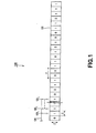
- FIG. 1 there is schematically illustrated in the form of a block diagram a conventional position transducer with one absolute track.
- the position transducer is generally indicated with a reference 120.
- the position transducer 120 is composed of one absolute track 121 and an ABS head 124 including n absolute track detectors 123 1 , 123 2 , ..., 123 a .
- ABS track the absolute track
- ABS track detector the ABS track detector
- the ABS track 121 is formed from a pattern in which micro-areas each represented by "0” and ones each represented by “1” are laid in array according to an a-order cyclic code.
- the micro-area represented by "0” and one represented by “1” are different in physical property from each other. For example, for the position transducer 120 to magnetically detect the position of the ABS head 124, the micro-areas "1" are magnetized but the micro-areas "0" are not.
- the ABS head 124 is movable longitudinally ofthe ABS track 121 as indicated by an arrow Y in FIG. 1.
- Each of the ABS detectors 123 1 to 123 a is provided in a position opposite to the ABS track 121. Also, when the micro-areas are laid at a pitch ⁇ , the ABS detectors 123 1 to 123 a are spaced a distance ⁇ corresponding to the micro-area pitch ⁇ from each other.
- the position transducer 120 can detect the position of the ABS head 124 in relation to the ABS track 121 on the basis of the ABS values detected by the ABS head 124.
- the position transducer 120 can have the ABS track 121 reduced in size in a direction indicated by an arrow Z in FIG. 1 because it has only one ABS track 121. That is, the position transducer 120 can be designed smaller.
- ABS detectors 123 1 to 123 n having quite the same capability of detecting a physical property and outputting a signal. Also it is difficult to provide all the micro-areas spaced at quite the same pitch ⁇ (as shown in FIG. 1) from each other when producing the ABS track 121.
- each ofthe ABS detectors 123 1 to 123 a is opposite to near the edge of a micro-area, the magnetic field to be detected is influenced by the adjacent micro-areas. Therefore, when a magnetized micro-area is adjacent to a micro-area not magnetized, there will take place near the edge of each micro-area an area where it is difficult for the ABS detector to stably output "1" or "0" signal.
- Position transducers capable of detecting the position of the ABS head in relation to the ABS track without error include two types which will be described below.
- the first one of the two types of position transducers is disclosed in the Japanese Unexampled Application Publication No. 1990-21216, Japanese Patent No. 2679207 and Japanese Unexamined Application Publication No. 1988-152314, respectively.
- This position transducer does not detect signal output from each of the ABS detectors that is opposite to near the edge of a micro-area but detects signal output from each of the ABS detectors that is opposite to near the center of the micro-area (which area will be referred to as "stable area” hereunder).
- FIG. 2 is also a block diagram of a variant of the aforementioned conventional position transducer.
- This conventional position transducer is generally indicated with a reference 140.
- an incremental track 142 having a pattern of constant-wavelength, alternating magnetic fields is juxtaposed with the ABS track 121.
- the position transducer 140 includes, in addition to the ABS head 124, an incremental track head 144 having two incremental track detectors 143 1 and 143 2 .
- the position transducer 140 is adapted such that judging from a signal output from the incremental track head 144 that each of the ABS detectors 123 1 to 123 a is in the stable area, it detects signal outputs from the ABS detectors 123 1 to 123 a .
- each of the ABS detectors 123 1 to 123 a have to be in the stable area at that moment. If none of the ABS detectors 123 1 to 123 a are in their respective stable areas, the position transducer 140 cannot detect any position of the ABS head 124 in relation to the ABS track 121 before the ABS head 124 is moved until each of the ABS detectors 123 1 to 123 a moves into the stable area. Namely, the position transducer 140 can hardly detect the position of the ABS head 124 in relation to the ABS track 121 the movement it is applied with the power.
- the second type of position transducer is disclosed in the Japanese Patent Nos. 2571393,2571394,3063044 and 3103266.
- the positional transducer includes a sets of ABS detectors, each set including two ABS detectors. In this position transducer, signal output from one of the two ABS detectors that is opposite to the stable area is used to detect an a-bit code.
- the ABS head includes 2n ABS detectors to detect an n-bit code indicating an a-bit code. That is, the position transducer will have a larger number of ABS detectors for the number of bits in a code the ABS head detects. Since many ABS detections are made in the position transducer, the ABS head will possibly have to be designed large and corresponding addition of wires and the like will possibly cause the circuit to be more complicated. Therefore, this position transducer can hardly be designed compact. Also, since the position transducer is produced through many steps, it is difficult to produce it with less costs.
- Japanese Unexamined Application Publication No. 1990-284025 discloses a positional transducer which detects an a-bit code by an ABS head composed of (a + ⁇ ) ( ⁇ is an integer larger than 1) ABS detectors nearly equidistantly spaced from each other.
- the ABS detectors are so disposed that when the ABS head is moved in relation o the ABS track, one ABS detector at the maximum will be opposite to near the boundary between a micro-area and a one adjacent to the micro-area, and the value ⁇ is decided so that one code will take place in the effective length of measurement taking in account a case in which a code is detected by the ABS head including also an ABS detector whose output is unstable.
- the number of ABS detectors provided in the position transducer is 2a - 1. Therefore, for this position transducer, it is difficult to design the ABS head compact and simplify the circuit.
- a position transducer capable of accurately detecting an n-bit code by an absolute track head including n+m ( n is a larger integer than 3 and m is a larger integer than 1) absolute track detectors even when it includes one absolute track and also capable of detecting the position of the absolute track head in relation to the absolute track independently of the position of each absolute track detector.
- the position transducer according to the present invention will be described concerning a linear encoder as an embodiment thereofwith reference to FIGS. 3 to 18.
- the linear encoder is generally indicated with a reference 1.
- the linear encoder 1 includes an absolute track (will be referred to as "ABS track” hereunder) 2, incremental track (will be referred to as “INC track” hereunder) 3, absolute track head (will be referred to as “ABS head” hereunder) 4, incremental track head (will be referred to as “INC head” hereunder) 5 and an absolute position detector 6.
- the ABS track 2 is a magnetic pattern in which micro-areas each represented by "0" and those each represented by “1” are laid in array according to an n-order cyclic code ( n is an integer larger than 3). One micro-area indicates one bit of the code.
- the cyclic code is a a maximum periodic series generated by a quartic primitive polynominal. That is, the ABS track 2 has such a magnetic field pattern that when a 4-bit code is sequentially read from the ABS track 2 while being moved bit by bit, the same 4-bit code will not take place again within an effective length of measurement.
- the micro-area represented by "0” is not magnetized while the micro-area represented by "1” is magnetized.
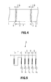
- the micro-area represented by "1” is so magnetized as to have the magnetic pole changed from N to S and from S to N in the direction from one edge of a micro-area near an adjacent micro-area toward another edge of the micro-area near another adjacent micro-area as shown in FIG. 3.
- an area S which will be influenced by the adjacent micro-area as shown in FIG. 4.
- the area S influenced by the adjacent area will be referred to as "unstable area S” and an area T not influenced by adjacent area will be referred to as "stable area T”.
- ABS track 2 in this embodiment is produced by the method disclosed in the Japanese Unexamined Application Patent No. 1997-264760 previously filed by the Applicant. That is, in the ABS track 2, when magnetized micro-areas S exist successively, the pitch of them except for one is ⁇ and the pitch of the one magnetized micro-area is 3/4 ⁇ . Also, in the ABS track 2, when the magnetized micro-areas exist discretely, the pitch of them is 3/4 ⁇ .
- the INC track 3 is a magnetic field pattern composed of alternating magnetic fields of 2 ⁇ in wavelength, and is juxtaposed to the ABS track 2.
- the ABS head 4 detects an n-bit code from the ABS track 2.
- the ABS head 4 detects a 4-bit code.
- the ABS head 4 is provided to be movable longitudinally of the ABS track 2.
- the ABS head 4 includes (n+m) ( m is a larger integer than 1) absolute track detectors 10 1 , 10 2 , ..., 10 n+m-1 and 10 m+n . It should be noted that in the following explanation, the absolute track detector will be referred to as "ABS detector”. The ABS head 4 will be described in detail later.
- the INC head 5 is provided to be movable longitudinally of the INC track 3 as indicated with an arrow B in FIG. 3. Also, the INC head 5 moves along with the ABS head 4.
- the INC head 5 includes four incremental track detectors 11 1 , 11 2 11 3 and 11 4 and a differential output detector 12 as shown in FIG. 5. It should be noted that in the following explanation, the incremental tack had will be referred to as "INC head".
- Each of the INC detectors 11 1 to 11 4 detects a magnetic field from the INC track 3 and outputs a detection signal.
- Each of the INC detectors 11 1 to 11 4 includes an MR element.
- the INC detectors 11 1 to 11 4 are disposed in array adjacently to each other longitudinally of the INC track 3. Further, the interval between two successive ones of the INC detectors 11 1 to 11 4 is ⁇ /2.
- the absolute position detector 6 computes based on a differential output between the INC detectors 11 1 and 11 3 and a differential output between the INC detectors 11 2 and 11 4 to detect from which micro-area of the ABS track 2 the ABS detector 10 1 has detected a magnetic field.
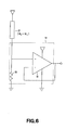
- the differential output detector 12 includes also an output detection circuit 14 as shown in FIG. 6.
- the output detection circuit 14 includes a resistor 15 and an operational amplifier 16.
- the differential output detector 12 is connected in serial to the resistor 15.
- the output detection circuit 14 outputs a potential at a midpoint between the differential output detector 12 and resistor 15. Differentiating the output the differential output detector 12 from the outputs from the ABS detectors 10 1 to 10 n+m , the outputs from the ABS detectors 10 1 to 10 n+m are little influenced by any noise and vary less with a change of the ambient temperature.
- the absolute position detector 6 acquires an absolute position signal indicative of a position of the ABS head 4 in relation to the ABS track 2 on the basis of outputs from the ABS head 4 and INC head 5. As shown in FIG. 7, the absolute position detector 6 includes a first differential output block 20, interpolation block 21, select signal generation block 22, second differential output block 23, signal selector 24, ROM 25 and a computation block 26. The absolute position detector 6 will be described in detail later.
- ABS head 4 will be described in detail herebelow:
- the ABS head 4 has the (n+m) ABS detectors 10 1 to 10 n+m laid in array longitudinally of the ABS track 2. Each of the ABS detectors 10 1 to 10 n+m detects a magnetic field from the ABS track 2. Each of the ABS detectors 10 1 to 10 n+m outputs a signal indicative of a logical value "1" (will be referred to as “1” signal hereunder) when it is opposite to a micro-area represented by "1”, and outputs a signal indicative of a logical value "0" (will be referred to as "0" signal hereunder) when it is opposite to a micro-area represented by "0".
- each of the ABS detectors 10 1 to 10 n+m when each of the ABS detectors 10 1 to 10 n+m is opposite to an unstable area S near the boundary between a micro-area represented by "1" and a one represented by "0", it can hardly provide a stable output because an adjacent micro-area will influence the magnitude of a magnetic field to be detected, and thus can hardly output definite "1" and "0" signals.
- Each of the ABS detectors 10 1 to 10 n+m detects each bit code by detecting a magnetic field from the ABS track 2.
- the value m should preferably be smaller, and more preferably be 1 or 2.
- the ABS head 4 has to include a larger number of ABS detectors for the number of bits of a code to be detected. With the increased number of the ABS detectors, the circuit of the ABS head 4 will possibly be larger and more complicated.
- the linear encoder 1 can hardly be designed compact. Also, with the more complicated circuit, the linear encoder 1 can hardly be produced with less costs.
- ABS detector 10 1 is constructed as will be described below. It should be noted that since all the ABS detectors 10 1 to 10 n+m are constructed identically to each other, the explanation of the construction of the ABS detector 10 1 is applied to the remaining ABS detectors 10 2 to 10 n+m .
- the ABS detector 10 1 includes two MR elements 10 1a and 10 1b connected in series to each other and spaced a distance of ⁇ /4 from each other.
- the MR element 10 1a detects a magnetic field from the ABS track 2 and has the resistance thereof varies like the waveform shown in FIG. 8(A).
- the MR element 10 1b detects a magnetic field from the ABS track and has the resistance thereof varied like the waveform shown in FIG. 8(B).
- the change in resistance of the ABS detector 10 1 is an addition of the resistance change of the MR element 10 1a and that of the MR element 10 1b , and the resistance varies like the waveform shown in FIG. 8(C).
- the ABS detector 10 1 includes an output detection circuit 14 as shown in FIG. 6.
- the ABS detector 10 1 is connected in series to the resistor 15. Thus, the potential at a midpoint between the ABS detector 10 1 and resistor 15 is outputted as signal from the ABS detector 10 1 .
- the ABS detectors 10 1 to 10 n+m are so disposed that a distance ⁇ 1 between the first one and (n+m)th one of the ABS detectors satisfies a requirement given by a following expression (1) and a distance ⁇ 2 between the ABS detectors 10 1 to 10 n+m satisfies a requirement given by a following expression (2), as will be seen in FIG. 9.
- ABS detectors 10 1 to 10 n+m are positioned to satisfy the requirements given by the expressions (1) and (2), at least n ABS detectors among the (n+m) ABS detectors 10 1 to 10 n+m will be opposite to the stable areas T of adjacent micro-areas.
- n ABS detectors opposite to n different stable areas T are selected from among the ABS detectors 10 1 to 10 n+m and an n-bit code is judged based on signal outputs from the selected ABS detectors.
- ABS detectors 10 1 to 10 n+m when the value ⁇ 2 is smaller than 2 ⁇ , two or more ABS detectors will be opposite to one stable area T and at least n ones of the ABS detectors 10 1 to 10 n+m will not be opposite to n different stable areas T, in some cases.
- the ABS detectors 10 1 and 10 2 are opposite to the same unstable area S as the case may be, so no 4-bit code cannot be detected.
- the ABS detectors 10 3 , 10 4 and 10 5 are not shown in FIG. 11.
- the value ⁇ 2 should preferably be generally fixed.
- the ABS detectors opposite to the unstable areas S will shift one after another at a constant interval. Therefore, the ABS detectors can be selected at the constant interval based on the INC value which will be described in detail later. That is to say, when the value ⁇ 2 is generally fixed, it is easier to select the ABS detectors, where by the circuit configuration of the select signal generation block 25 etc. can be more simplified.
- the ABS head 4 in this embodiment has five ABS detectors 10 1 to 10 5 laid in array at intervals of 4 ⁇ /5 as shown in FIG. 13. Four of these five ABS detectors 10 1 to 10 5 detects a 4-bit code.
- the resistance of each of the ABS detectors 10 1 to 10 5 varies as shown in FIG. 8. Namely, the resistance of the ABS detector 10 1 changes like the waveform shown in FIG. 8(C), that of the ABS detector 10 2 changes like the waveform shown in FIG. 8(D), that ofthe ABS detector 10 3 changes like the waveform shown in FIG. 8(E), that of the ABS detector 10 4 changes like the waveform shown in FIG. 8(F), and that of the ABS detector 10 5 changes like the waveform shown in FIG. 8(G).
- the distance ⁇ 1 between the ABS detectors 10 1 and 10 5 is 3 ⁇ + ⁇ /5 and larger than 3 ⁇ + ⁇ /10.
- the distance ⁇ 2 between the ABS detectors 10 1 and 10 5 is 4 ⁇ /5 and thus it is larger than ⁇ /10 and smaller than 9 ⁇ /10. That is, the ABS detectors 10 1 and 10 5 are disposed to satisfy the requirements given by the aforementioned expressions (1) and (2).
- the ABS detector 10 1 When 0 ⁇ ⁇ ⁇ ⁇ /5, the ABS detector 10 1 is opposite to an unstable area S while the ABS detectors 10 2 , 10 3 , 10 4 and 10 5 are opposite to stable areas T, as shown in FIG. 14(A). Therefore, when 0 ⁇ ⁇ ⁇ ⁇ /5, the ABS detectors 10 2 , 10 3 , 10 4 and 10 5 will be selected to provide a code "1101".
- the ABS detector 10 2 is opposite to an unstable area S while the ABS detectors 10 1 , 10 3 , 10 4 and 10 5 are opposite to stable areas T, as shown in FIG. 14(B). Therefore, when ⁇ /5 ⁇ ⁇ ⁇ 2 ⁇ /5, the ABS detectors 10 1 , 10 3 , 10 4 and 10 5 will be selected to provide a code "1101".
- the ABS detector 10 3 is opposite to an unstable area S while the ABS detectors 10 1 , 10 2 , 10 4 and 10 5 are opposite to stable areas T as shown in FIG. 14(C). Therefore, when 2 ⁇ /5 ⁇ ⁇ ⁇ 3 ⁇ /5, the ABS detectors 10 1 , 10 2 , 10 4 and 10 5 will be selected to provide a code "1101".
- the ABS detector 10 4 is opposite to an unstable area S while the ABS detectors 10 1 , 10 2 , 10 3 and 10 5 are opposite to stable areas T as shown in FIG. 14(D). Therefore, when 3 ⁇ /5 ⁇ ⁇ ⁇ 4 ⁇ /5, the ABS detectors 10 1 , 10 2 , 10 3 and 10 5 will be selected to provide a code "1101".
- the ABS detector 10 5 when 4 ⁇ /5 ⁇ ⁇ ⁇ ⁇ ⁇ (0), the ABS detector 10 5 is opposite to an unstable area S while the ABS detectors 10 1 , 10 2 , 10 3 and 10 4 are opposite to stable areas T as shown in FIG. 14(E). Therefore, when 3 ⁇ /5 ⁇ ⁇ ⁇ ⁇ ⁇ , the ABS detectors 10 1 , 10 2 , 10 3 and 10 4 will be selected to provide a code "1101".
- the first differential output block 20 differentiates between differential output between the INC detectors 11 1 and 11 3 and a differential output between the INC detectors 11 2 and 11 3 .
- the differential output between the INC detectors 11 1 and 11 3 and that between the INC detectors 11 2 and 11 2 are 90° out phase from each other.
- the interpolation block 21 detects an INC value on the basis of the differential output between the INC detectors 11 1 and 11 3 and that between the INC detectors 11 2 and 11 4 .
- the INC value indicates an absolute position of the ABS detector 10 1 opposite to a micro-area.
- the micro-area is equally divided by w (w is a natural number) longitudinally of the ABS track 2.
- the w equally divided areas of the micro-area are assigned INC values 0, 1, 2, ..., w-1, respectively to sequentially from one edge of the micro-area. It should be noted that the INC value is decided by the method disclosed in the Japanese Patent No. 2571394 etc.
- the select signal generation block 22 judges to-be-selected ABS detectors based on the INC values to make select signals from the result of judgment and supply them to the signal selector 24.
- the value ⁇ is decided based on the INC value.
- the ABS detectors 10 2 , 10 3 , 10 4 and 10 5 are selected.
- ⁇ /5 ⁇ ⁇ ⁇ 2 ⁇ /5 the ABS detectors 10 1 , 10 3 , 10 4 and 10 5 are selected.
- 2 ⁇ /5 ⁇ ⁇ ⁇ 3 ⁇ /5 the ABS detectors 10 1 , 10 2 , 10 4 and 10 5 are selected.
- the ABS detectors 10 1 ,10 2 ,10 3 and 10 5 are selected.
- the ABS detectors 10 1 , 10 2 , 10 3 and 10 4 are selected.
- the second differential output block 23 differentiates between the differential output between each of the ABS detectors 10 1 to 10 5 and the differential output detector 12, and supplies the result to the signal selector 24.
- the signal selector 24 selects the signal supplied from the second differential output block 23 on the basis of the select signal.
- the selected signal is supplied as an n-bit code to the ROM 25.
- the signal selector 24 supplies a 4-bit code to the ROM 25.
- the ROM 25 has stored therein data indicative of the relation between the n-bit code supplied from the signal selector 24 and sectional absolute position signal indicating, by a section, a position of the ABS head 4 in relation to the ABS track 2.
- the ROM 25 converts the n-bit signal into a sectional absolute position signal according to the data stored therein.
- the computation block 26 adds the INC value and sectional absolute position signal together. By adding them together, the computation 26 provides an absolute position signal indicating a position of the ABS head 4 in relation to the ABS track 2 with an accuracy of 1/w of the sectional absolute position signal.
- the first differential output block 20 detects a differential output between the INC detectors 11 1 and 11 3 , and also a differential output between the INC detectors 11 2 and 11 4 .
- the interpolation block 21 detects an INC value on the basis of the differential output between the INC detectors 11 1 and 11 3 and that between the INC detectors 11 2 and 11 4 .
- the INC value is supplied to the select signal generation block 22 and computation block 26.
- the select signal generation block 22 generates, based on the INC value, a select signal indicating which of signal outputs from the ABS detectors 10 1 to 10 5 is to be selected.
- the select signal is supplied to the signal selector 24.
- the second differential output block 23 differentiates between each of the ABS detectors 10 1 to 10 5 and the differential output detector 12, and supplies the result to the signal selector 24.
- the signal selector 24 selects, based on the select signal supplied from the select signal generation block 22, four of the five signals supplied from the second differential output block 23, and supplies the selected signals as a 4-bit code to the ROM 25.
- the ROM 25 converts the 4-bit code supplied from the signal selector 24 into a sectional absolute position signal.
- the computation block 26 adds the INC value and sectional absolute position together to provide an absolute position signal.
- one of the methods of attaining a higher accuracy and resolution in the linear encoder is to narrow the pitch of the micro-areas.
- the value ⁇ becomes correspondingly smaller.
- the value ⁇ will not vary. More particularly, with the smaller pitch, the proportion of an unstable area S in a micro-area becomes larger.
- ⁇ ⁇ /10.
- positioning of the ABS detectors 10 1 to 10 5 to satisfy the requirements given by the aforementioned expressions (1) and (2) as well as a following expression (3) facilitates to determine the positions of the ABS detectors 10 1 to 10 5 : s ⁇ - 2 ⁇ ⁇ ⁇ 3 ⁇ s ⁇ + 2 ⁇ where s is a natural number and indicates a number of stable areas T formed between different unstable areas S when two of the ABS detectors 10 1 to 10 5 are opposite to the different unstable areas S, respectively.
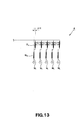
- an ABS head 40 includes six ABS detectors 41 1 , 41 2 , 41 3 , 41 4 , 41 5 and 41 6 . These ABS detectors 41 1 to 41 6 may be the same as the ABS detectors 10 1 to 10 5 .
- ABS detectors 41 1 to 41 6 are disposed in a position relation as will be described below.
- the ABS detectors 41 1 to 41 6 are positioned to satisfy the requirement given by the above expression (3).
- the first ABS detector 41 1 and fifth ABS detector 41 5 are positioned at a distance of 3 ⁇ between them.
- ABS detectors 41 2 , 41 3 and 41 4 are disposed at a distance of 3 ⁇ /4 from their respective adjacent ABS detectors.
- the ABS detectors not yet positioned are positioned to satisfy the requirements given by the expressions (1) and (2).
- the ABS detector 41 5 is position at a distance of ⁇ /2 from the ABS detector 41 6 .
- ABS detectors 41 1 to 41 6 are positioned as above, two adjacent ABS detectors will not be opposite to two unstable areas S formed across one micro-area and at least four of the ABS detectors 41 1 to 41 6 will be opposite to stable areas T of four adjacent micro-areas, as shown in FIG. 16(B).
- the distance between the first ABS detector 41 1 and fifth ABS detector 11 5 is determined to satisfy the requirement given by the expression (3) before the ABS detectors 41 1 to 41 6 are positioned.
- the distance between two other ABS detectors not adjacent to each other may be determined to satisfy the requirement given by the expression (3) before the ABS detectors 41 1 to 41 6 .
- the ABS detectors 41 1 to 41 6 in the ABS head 40 will be in a position relation as shown in FIG. 18.
- the distance between the first ABS detector 41 1 and third ABS detector 41 3 is set to ⁇ .
- the ABS detector 41 2 is positioned at a distance of ⁇ /2 from the adjacent ABS detector.
- the ABS detectors 41 4 , 41 5 and 41 6 are positioned at a distance of 3 ⁇ /4 from their respective adjacent ABS detector.
- the select signal for selection of n ABS detectors may not be generated based on the INC value. For example, it may be generated on the basis of an index or mark detected from a predetermined place.
- the present invention has been described concerning its application to the linear encoder but the present invention is applicable to any other position transducer than any linear encoder, for example, a rotary encoder.
- the present invention has been described concerning its application to the magnetic position transducer but the present invention is applicable to any other position transducer than the magnetic type one, for example, an optical or capacitance type position transducer.
- the position transducer according to the present invention can accurately detect an n-bit signal from an absolute track by an absolute track head including (n+m) absolute track detectors even when there is provided only one absolute track. Therefore, the position transducer according to the present invention can have the circuit thereof constructed more simple, compact and less expensive by setting the value m to 1 or 2.
- the position transducer according to the present invention can detect the position of an absolute track head in relation to an absolute track even when an absolute track detector is opposite to near the edge of a micro-area. Therefore, the position transducer according to the present invention can detect the position of the absolute track head in relation to the absolute track independently of the position of the absolute track detector. Also, the position transducer according to the present invention can detect an n-bit code over the effective length of measurement of the absolute track. Further, the position transducer according to the present invention can detect the position of the absolute track head in relation to the absolute track with a high resolution.
Landscapes
- Physics & Mathematics (AREA)
- General Physics & Mathematics (AREA)
- Transmission And Conversion Of Sensor Element Output (AREA)
Applications Claiming Priority (2)
| Application Number | Priority Date | Filing Date | Title |
|---|---|---|---|
| JP2002064566 | 2002-03-08 | ||
| JP2002064566A JP4166490B2 (ja) | 2002-03-08 | 2002-03-08 | 位置検出装置 |
Publications (3)
| Publication Number | Publication Date |
|---|---|
| EP1342993A2 true EP1342993A2 (fr) | 2003-09-10 |
| EP1342993A3 EP1342993A3 (fr) | 2005-06-08 |
| EP1342993B1 EP1342993B1 (fr) | 2008-05-07 |
Family
ID=27751295
Family Applications (1)
| Application Number | Title | Priority Date | Filing Date |
|---|---|---|---|
| EP03004854A Expired - Lifetime EP1342993B1 (fr) | 2002-03-08 | 2003-03-05 | Capteur de position |
Country Status (4)
| Country | Link |
|---|---|
| US (1) | US6772088B2 (fr) |
| EP (1) | EP1342993B1 (fr) |
| JP (1) | JP4166490B2 (fr) |
| DE (1) | DE60320694D1 (fr) |
Families Citing this family (4)
| Publication number | Priority date | Publication date | Assignee | Title |
|---|---|---|---|---|
| JP4499399B2 (ja) * | 2003-11-07 | 2010-07-07 | ソニーマニュファクチュアリングシステムズ株式会社 | 位置検出装置 |
| US7352293B1 (en) * | 2007-04-23 | 2008-04-01 | Hewlett-Packard Development Company, L.P. | Multi-mode encoder output generator |
| US9733317B2 (en) * | 2014-03-10 | 2017-08-15 | Dmg Mori Seiki Co., Ltd. | Position detecting device |
| JP7258515B2 (ja) | 2018-10-26 | 2023-04-17 | Dmg森精機株式会社 | 位置検出装置および搬送装置 |
Family Cites Families (12)
| Publication number | Priority date | Publication date | Assignee | Title |
|---|---|---|---|---|
| JPS5099564A (fr) | 1973-12-28 | 1975-08-07 | ||
| JPS63177019A (ja) | 1986-10-09 | 1988-07-21 | Alpine Electron Inc | 位置センサ |
| JPH01152314A (ja) | 1987-12-10 | 1989-06-14 | Nikon Corp | アブソリュートエンコーダ |
| JPH0221216A (ja) | 1988-07-11 | 1990-01-24 | Nikon Corp | アブソリュートエンコーダ |
| JPH02284025A (ja) | 1989-04-25 | 1990-11-21 | Nikon Corp | 1トラック型アブソリュート・エンコーダ |
| FR2647679B1 (fr) | 1989-06-02 | 1991-08-23 | Hospal Ind | Dispositif et procede de mesure de l'ultrafiltration dans un rein artificiel |
| JPH0363044A (ja) | 1989-08-02 | 1991-03-19 | Olympus Optical Co Ltd | レーザプローブ |
| JP3063044B2 (ja) | 1992-02-13 | 2000-07-12 | 日本サーボ株式会社 | アブソリュートエンコーダ |
| JP3103266B2 (ja) | 1994-03-25 | 2000-10-30 | オークマ株式会社 | 絶対位置検出装置 |
| JP3454002B2 (ja) | 1996-03-29 | 2003-10-06 | ソニー・プレシジョン・テクノロジー株式会社 | 位置検出装置 |
| JP3433606B2 (ja) * | 1996-03-29 | 2003-08-04 | ソニー・プレシジョン・テクノロジー株式会社 | 位置検出装置 |
| JP4166488B2 (ja) * | 2002-03-05 | 2008-10-15 | ソニーマニュファクチュアリングシステムズ株式会社 | 位置検出装置 |
-
2002
- 2002-03-08 JP JP2002064566A patent/JP4166490B2/ja not_active Expired - Fee Related
-
2003
- 2003-02-21 US US10/371,875 patent/US6772088B2/en not_active Expired - Lifetime
- 2003-03-05 DE DE60320694T patent/DE60320694D1/de not_active Expired - Lifetime
- 2003-03-05 EP EP03004854A patent/EP1342993B1/fr not_active Expired - Lifetime
Also Published As
| Publication number | Publication date |
|---|---|
| US20030187608A1 (en) | 2003-10-02 |
| EP1342993A3 (fr) | 2005-06-08 |
| JP2003262540A (ja) | 2003-09-19 |
| EP1342993B1 (fr) | 2008-05-07 |
| US6772088B2 (en) | 2004-08-03 |
| DE60320694D1 (de) | 2008-06-19 |
| JP4166490B2 (ja) | 2008-10-15 |
Similar Documents
| Publication | Publication Date | Title |
|---|---|---|
| US10724877B2 (en) | Compact pseudorandom scale and read head for an inductive type absolute position encoder | |
| US6271661B2 (en) | Absolute position transducer having a non-binary code-track-type scale | |
| US5068529A (en) | Absolute position detection encoder | |
| US6157188A (en) | Compact, long-range absolute position transducer with an extensible compact encoding | |
| EP0111866B1 (fr) | Appareil pour la détection magnétique de positions | |
| US7571552B2 (en) | Scale reading apparatus | |
| US5412317A (en) | Position detector utilizing absolute and incremental position sensors in combination | |
| US4757244A (en) | Method and apparatus for detecting absolute position | |
| US5825307A (en) | Absolute linear encoder and method of production utilizing index and counter channels | |
| US9778072B1 (en) | Absolute electromagnetic position encoder | |
| US7015832B2 (en) | Pulse width modulation based digital incremental encoder | |
| EP1380815B1 (fr) | Dispositif de détection de position | |
| JPH01502452A (ja) | 位置決め装置用スケール | |
| EP1342993B1 (fr) | Capteur de position | |
| EP1828724B1 (fr) | Codage de position angulaire, de vitesse et de direction d'un organe rotatif | |
| JP4166488B2 (ja) | 位置検出装置 | |
| JP4499399B2 (ja) | 位置検出装置 | |
| JPH05231880A (ja) | アブソリュートエンコーダ | |
| JPH07104180B2 (ja) | 磁気回転エンコーダ系 | |
| JP2699542B2 (ja) | 1トラック型アブソリュートエンコーダ用符号板及び読取ヘッド | |
| JPS6146461Y2 (fr) | ||
| JPH05223595A (ja) | アブソリュートエンコーダ | |
| EP0382856B1 (fr) | Codeur magnetique de position absolue | |
| JP2004347358A (ja) | 変位測定装置 | |
| JP2004061440A (ja) | 位置検出装置 |
Legal Events
| Date | Code | Title | Description |
|---|---|---|---|
| PUAI | Public reference made under article 153(3) epc to a published international application that has entered the european phase |
Free format text: ORIGINAL CODE: 0009012 |
|
| AK | Designated contracting states |
Kind code of ref document: A2 Designated state(s): AT BE BG CH CY CZ DE DK EE ES FI FR GB GR HU IE IT LI LU MC NL PT RO SE SI SK TR |
|
| AX | Request for extension of the european patent |
Extension state: AL LT LV MK |
|
| PUAL | Search report despatched |
Free format text: ORIGINAL CODE: 0009013 |
|
| AK | Designated contracting states |
Kind code of ref document: A3 Designated state(s): AT BE BG CH CY CZ DE DK EE ES FI FR GB GR HU IE IT LI LU MC NL PT RO SE SI SK TR |
|
| AX | Request for extension of the european patent |
Extension state: AL LT LV MK |
|
| RAP1 | Party data changed (applicant data changed or rights of an application transferred) |
Owner name: SONY MANUFACTURING SYSTEMS CORPORATION |
|
| 17P | Request for examination filed |
Effective date: 20051116 |
|
| AKX | Designation fees paid |
Designated state(s): DE GB |
|
| RAP1 | Party data changed (applicant data changed or rights of an application transferred) |
Owner name: SONY MANUFACTURING SYSTEMS CORPORATION |
|
| GRAP | Despatch of communication of intention to grant a patent |
Free format text: ORIGINAL CODE: EPIDOSNIGR1 |
|
| GRAS | Grant fee paid |
Free format text: ORIGINAL CODE: EPIDOSNIGR3 |
|
| GRAA | (expected) grant |
Free format text: ORIGINAL CODE: 0009210 |
|
| AK | Designated contracting states |
Kind code of ref document: B1 Designated state(s): DE GB |
|
| REG | Reference to a national code |
Ref country code: GB Ref legal event code: FG4D |
|
| REF | Corresponds to: |
Ref document number: 60320694 Country of ref document: DE Date of ref document: 20080619 Kind code of ref document: P |
|
| PLBE | No opposition filed within time limit |
Free format text: ORIGINAL CODE: 0009261 |
|
| STAA | Information on the status of an ep patent application or granted ep patent |
Free format text: STATUS: NO OPPOSITION FILED WITHIN TIME LIMIT |
|
| 26N | No opposition filed |
Effective date: 20090210 |
|
| REG | Reference to a national code |
Ref country code: DE Ref legal event code: R082 Ref document number: 60320694 Country of ref document: DE Representative=s name: MUELLER - HOFFMANN & PARTNER PATENTANWAELTE, DE |
|
| REG | Reference to a national code |
Ref country code: DE Ref legal event code: R082 Ref document number: 60320694 Country of ref document: DE Representative=s name: MUELLER - HOFFMANN & PARTNER PATENTANWAELTE, DE Effective date: 20120730 Ref country code: DE Ref legal event code: R081 Ref document number: 60320694 Country of ref document: DE Owner name: MORI SEIKI CO., LTD., JP Free format text: FORMER OWNER: SONY MANUFACTURING SYSTEMS CORP., KUKI, JP Effective date: 20120711 Ref country code: DE Ref legal event code: R081 Ref document number: 60320694 Country of ref document: DE Owner name: MORI SEIKI CO., LTD., JP Free format text: FORMER OWNER: MAGNESCALE CO., LTD., TOKYO, JP Effective date: 20120730 Ref country code: DE Ref legal event code: R082 Ref document number: 60320694 Country of ref document: DE Representative=s name: MUELLER - HOFFMANN & PARTNER PATENTANWAELTE, DE Effective date: 20120711 Ref country code: DE Ref legal event code: R081 Ref document number: 60320694 Country of ref document: DE Owner name: MORI SEIKI CO., LTD., YAMATOKORIYAMA, JP Free format text: FORMER OWNER: SONY MANUFACTURING SYSTEMS CORP., KUKI, SAITAMA, JP Effective date: 20120711 Ref country code: DE Ref legal event code: R081 Ref document number: 60320694 Country of ref document: DE Owner name: MORI SEIKI CO., LTD., YAMATOKORIYAMA, JP Free format text: FORMER OWNER: MAGNESCALE CO., LTD., TOKYO, JP Effective date: 20120730 Ref country code: DE Ref legal event code: R082 Ref document number: 60320694 Country of ref document: DE Representative=s name: MUELLER HOFFMANN & PARTNER PATENTANWAELTE MBB, DE Effective date: 20120711 Ref country code: DE Ref legal event code: R082 Ref document number: 60320694 Country of ref document: DE Representative=s name: MUELLER HOFFMANN & PARTNER PATENTANWAELTE MBB, DE Effective date: 20120730 |
|
| REG | Reference to a national code |
Ref country code: GB Ref legal event code: 732E Free format text: REGISTERED BETWEEN 20150205 AND 20150211 |
|
| PGFP | Annual fee paid to national office [announced via postgrant information from national office to epo] |
Ref country code: DE Payment date: 20210319 Year of fee payment: 19 Ref country code: GB Payment date: 20210324 Year of fee payment: 19 |
|
| REG | Reference to a national code |
Ref country code: DE Ref legal event code: R119 Ref document number: 60320694 Country of ref document: DE |
|
| GBPC | Gb: european patent ceased through non-payment of renewal fee |
Effective date: 20220305 |
|
| PG25 | Lapsed in a contracting state [announced via postgrant information from national office to epo] |
Ref country code: GB Free format text: LAPSE BECAUSE OF NON-PAYMENT OF DUE FEES Effective date: 20220305 Ref country code: DE Free format text: LAPSE BECAUSE OF NON-PAYMENT OF DUE FEES Effective date: 20221001 |