EP1343191A2 - Maskenrahmen für Kathodenstrahlröhre - Google Patents
Maskenrahmen für Kathodenstrahlröhre Download PDFInfo
- Publication number
- EP1343191A2 EP1343191A2 EP20020024907 EP02024907A EP1343191A2 EP 1343191 A2 EP1343191 A2 EP 1343191A2 EP 20020024907 EP20020024907 EP 20020024907 EP 02024907 A EP02024907 A EP 02024907A EP 1343191 A2 EP1343191 A2 EP 1343191A2
- Authority
- EP
- European Patent Office
- Prior art keywords
- cathode ray
- ray tube
- mask frame
- panel
- height
- Prior art date
- Legal status (The legal status is an assumption and is not a legal conclusion. Google has not performed a legal analysis and makes no representation as to the accuracy of the status listed.)
- Withdrawn
Links
Images



Classifications
-
- H—ELECTRICITY
- H01—ELECTRIC ELEMENTS
- H01J—ELECTRIC DISCHARGE TUBES OR DISCHARGE LAMPS
- H01J29/00—Details of cathode-ray tubes or of electron-beam tubes of the types covered by group H01J31/00
- H01J29/02—Electrodes; Screens; Mounting, supporting, spacing or insulating thereof
-
- H—ELECTRICITY
- H01—ELECTRIC ELEMENTS
- H01J—ELECTRIC DISCHARGE TUBES OR DISCHARGE LAMPS
- H01J29/00—Details of cathode-ray tubes or of electron-beam tubes of the types covered by group H01J31/00
- H01J29/02—Electrodes; Screens; Mounting, supporting, spacing or insulating thereof
- H01J29/06—Screens for shielding; Masks interposed in the electron stream
- H01J29/07—Shadow masks for colour television tubes
- H01J29/073—Mounting arrangements associated with shadow masks
-
- H—ELECTRICITY
- H01—ELECTRIC ELEMENTS
- H01J—ELECTRIC DISCHARGE TUBES OR DISCHARGE LAMPS
- H01J2229/00—Details of cathode ray tubes or electron beam tubes
- H01J2229/07—Shadow masks
- H01J2229/0722—Frame
Definitions
- the present invention relates to a cathode ray tube, and in particular to a mask frame for a cathode ray tube which is capable of improving howling characteristics and drop characteristics by having an optimum design shape.
- a cathode ray tube includes a vacuous vessel consisting of a panel and a funnel.
- an electron beam emitted from an electron gun is deflected by a deflection yoke, passes plural electron beam passage holes formed at a shadow mask and lands onto a fluorescent surface formed onto the inner. surface of the panel, and accordingly a picture is displayed by each luminescent material of the fluorescent surface.
- Figure 1 is a schematic view illustrating the conventional cathode ray tube.
- a panel 1 as a front glass combines with a funnel 2 as a rear glass, and the internal space is sealed in a high vacuum state.
- the cathode ray tube includes the fluorescent surface 13 coated onto the inner surface of the panel 1 and performing a certain luminary function; the electron gun 6 installed at the end of the funnel 2 and emitting the electron beam 5; the deflection yoke 7 installed at the outer circumference of the funnel 2 and deflecting the electron beam 5 so as to be scanned appropriate to a size of the fluorescent surface 13; a shadow mask 8 installed at the rear of the panel 1 with a certain distance from the fluorescent surface 13; a mask frame 9 for supporting the shadow mask 8; and an inner shield 10 installed lengthily from the panel side to the funnel side and preventing color purity deterioration due to magnetic filed influence by shielding outer earth magnetism.
- the panel 1 has an almost rectangular shape. And, it consists of an effective portion 3 having the fluorescent surface 13 formed at the inner surface and a skirt portion 4 projected from the circumference of the effective portion 3 and combined with the funnel 2.
- a spring supporter 14 at which a support spring 11 for elastically supporting the mask frame 9 to the panel 1 is fixed, is installed inside the skirt portion 4 of the panel 1, and a reinforcing band 12 is installed around the outer circumference of the skirt portion 4 of the panel 1 in order to reinforce the combining outer circumference between the panel 1 and the funnel 2.
- the mask frame 9 includes a rectangular opening 21 formed at the inner surface to pass the electron beam 5; a bottom portion 24 consisting of two long side bottoms 22 and two short side bottoms 23; and a side portion 20 vertically extended from the bottom portion 24 to mount the shadow mask 8.
- An inner shield combining hole 28 is formed at the bottom portion 24 to combine the inner shield 10 with the mask frame 9.
- a stair-shaped bead 27 is respectively formed at regular intervals at a portion at which the bottom portion 24 meets the side portion 20 in order to improve strength of the mask frame 9.
- the side portion 20 is classified into two long sides 25 and two short sides 26 according to a length, and each side is connected with each other by forming a corner portion 29.
- the skirt portion 4 of the panel 1 can be reduced as a certain width ( ⁇ W).
- ⁇ W a size of the skirt portion 4 of the panel 1 can be reduced within the range of 10 ⁇ 15 mm.
- a height of the side portion 20 of the mask frame 9 is reduced, by the height reduction of the side portion 20, because an area of the combining surface of the shadow mask 8 and the mask frame 9 is reduced, a combining force is lowered, and accordingly howling characteristics and drop characteristics of the shadow mask 8 may be deteriorated.
- a mask frame for a cathode ray tube which is capable of preventing interference between the inner surface of a panel and a mask frame due to decrease of an interval between them according to sliming-down of a panel and improving howling characteristics and drop characteristics of the cathode ray tube by having an optimum shape.
- a mask frame for a cathode ray tube satisfies following equation 0.80 ⁇ a / (Xd / 4) + b / (Yd / 4) + c / (Dd / 4) ⁇ 1.25, wherein Xd is a long side length of the mask frame, Yd is a short side length thereof, Dd is a diagonal length thereof, a is a height of the center of the long side thereof, b is a height of the center of the short side thereof, and c is a height of the corner portion thereof.
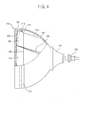
- Figure 4 is a schematic view illustrating a cathode ray tube in accordance with the present invention
- Figure 5 is a development view illustrating a mask frame of the cathode ray tube in accordance with the present invention.
- a panel 101 as a front glass combines with a funnel 102 as a rear glass, and the inner space is sealed as a high vacuum state.
- the cathode ray tube includes a fluorescent surface 113 coated onto the inner surface of the panel 101 and performing a certain luminary function; an electron gun 106 installed at the end of the funnel 102 and emitting an electron beam 105; a deflection yoke 107 installed at the outer circumference of the funnel 102 and deflecting the electron beam 105 so as to be scanned appropriate to a size of the fluorescent surface 113; a shadow mask 108 installed at the rear of the panel 101 with a certain distance from the fluorescent surface 113; a mask frame 109 for supporting the shadow mask 108; and an inner shield 110 installed lengthily from the panel side to the funnel side and preventing color purity deterioration due to magnetic filed influence by shielding outer earth magnetism.
- the panel 101 has an almost rectangular shape and having a curved inner surface and a substantially flat outer surface. And, it consists of an effective portion 103 having the fluorescent surface 113 formed at the inner surface and a skirt portion 104 projected from the circumference of the effective portion 103 and combined with the funnel 102.
- a spring supporter 114 at which a support spring 111 for elastically supporting the mask frame 109 to the panel 101 is fixed, is installed inside the skirt portion 104 of the panel 101, and a reinforcing band 112 is installed around the outer circumference of the skirt portion 104 of the panel 101 in order to reinforce the combining outer circumference of the panel 101 and the funnel 102.
- the mask frame 109 includes a rectangular opening 121 formed at the inner surface to pass the electron beam 105; a bottom portion 124 consisting of two long side bottoms 122 and two short side bottoms 123; a side portion 120 vertically extended from the bottom portion 124 to mount the shadow mask 108 on the inner side surface; a curved portion 130 curved from the bottom portion 124 at a certain angle in order to prevent the fluorescent surface 113 from being influenced by diffused reflection of the electron beam 105; an inner shield combining hole 128 formed at the bottom portion 124 to combine the inner shield 10 for reducing outer magnetic field influence with the mask frame 109; and a stair-shaped bead 127 respectively formed at regular intervals at a portion at which the bottom portion 124 meets the side portion 120 in order to improve strength of the mask frame 109.
- the side portion 120 is classified into two long sides 125 and two short sides 126 according to a length, and each long side 125 is connected with each short side 126 by forming each corner portion 129.
- the cathode ray tube in accordance with the present invention has the same/similar construction as/to that of the conventional cathode ray tube.
- the skirt portion 104 of the panel 101 is reduced as a certain amount in comparison with the conventional art.
- an optimum design value of the mask frame which is capable of solving interference problem between the panel 101 and the mask frame 109 occurred according to width reduction of the skirt portion 104 of the panel 101 and satisfying both howling characteristics and drop characteristics of the shadow mask 108 will be described.
- Equation 1 a is a height of the center of the long side 125 of the mask frame 109, b is a height of the center of the short side 126, c is a height of the corner portion 129, Xd is a length of the long side 125, Yd is a length of the short side 126, and Dd is a diagonal length of the mask frame 109.
- Equation (1) shows the sum of a ratio of each side height to each side length of the mask frame 109.
- Tables 1 and 2 respectively show a howling strength and a drop strength of the shadow mask of each 21 inch, 28 inch, 29 inch and 32 inch cathode ray tube.
- a 1/2 value of a diagonal length of the effective screen of the panel is within the range of 240 ⁇ 270mm.
- a 1/2 value of a diagonal length of the effective screen of the panel is within the range of 315 ⁇ 355mm
- a 1/2 value of a diagonal length of the effective screen of the panel is within the range of 365 ⁇ 395mm.
- the howling strength value is a required value for preventing howling occurrence in the shadow mask, and the lower the howling value, the less a tensile force is required for the shadow mask.
- the lower a required value the more it is preferable for the optimum design of the mask frame.
- the drop strength value means a limit value (power by gravity) which does not cause deformation of the shadow mask in drop impact.
- the limit value the more a curved surface support strength, it means the more easily the shadow mask stands impact.
- the howling strength is 2 ⁇ 3 kg/mm 2 , it can be considered as an optimum value in the howling characteristics.
- the drop strength is 21 ⁇ 23G, and it is advantageous in the drop characteristics in comparison with other ranges.
- Equation (2) 0.80 ⁇ a/(Xd/4)+b/(Yd/4)+c/(Dd/4) ⁇ 1.20 ⁇ 21" ⁇
- the howling strength is 2 ⁇ 3kg/mm 2 , it is advantageous in the howling characteristics.
- the drop strength is 19 ⁇ 20G, and it is advantageous in the drop characteristics in comparison with other ranges.
- Equation (3) 0.90 ⁇ a/(Xd/4)+b/(Yd/4)+c/(Dd/4) ⁇ 1.25 ⁇ 28" ⁇
- the howling strength is 2 ⁇ 3kg/mm 2 , it is advantageous in the howling characteristics.
- the drop strength is 21 ⁇ 23G, and it is advantageous in the drop characteristics in comparison with other ranges.
- Equation (4) 0.90 ⁇ a/(Xd/4)+b/(Yd/4)+c/(Dd/4) ⁇ 1.25 ⁇ 29" ⁇
- the howling strength is 2 ⁇ 3kg/mm 2 , it is advantageous in the howling characteristics.
- the drop strength is 18 ⁇ 19G, and it is advantageous in the drop characteristics in comparison with other ranges.
- Equation (5) 0.90 ⁇ a/(Xd/4)+b/(Yd/4)+c/(Dd/4) ⁇ 1.20 ⁇ 32" ⁇
- the mask frame 109 of the cathode ray tube in accordance with the present invention, when a height of the side portion 20 of the mask frame 109 is reduced according to reduction of a width of the panel 101, interference between the inner surface of the panel 101 and the end of the mask frame 109 can be prevented, and the howling and drop characteristics conditions required for the shadow mask 108 can be satisfied.
- Tables 3 ⁇ 6 respectively show measures of a long side length of the mask frame, a short side length thereof, a diagonal length thereof, a long side center height thereof, a short side center height thereof and a corner portion height and compare the measures with those of the conventional mask frame.
- an optimum design value of the mask frame satisfying both the howling and drop characteristics is a value of Equation (1), herein a howling strength value is a minimum and a drop strength value is a maximum. In more detail, it is 1.15 in the 21 inch cathode ray tube, 0.97 in the 28 inch cathode ray tube, 1.10 in the 29 inch cathode ray tube and 1.06 in the 32 inch cathode ray tube.
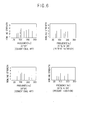
- Figure 6 is graphs respectively illustrating howling characteristics of the shadow mask of the cathode ray tube in accordance with the conventional art and the present invention, a howling frequency and occurrence frequency thereof are shown.
- the howling frequency band is varied in the range of 20Hz ⁇ 350Hz according to strength variation of the shadow mask installed on the mask frame in accordance with the prior art
- the howling frequency band is in the range of 20Hz ⁇ 200Hz.
- the frequency occurrence number of the present invention is lower than that of the conventional art.
- the mask frame in accordance with the present invention when the mask frame in accordance with the present invention is applied, the howling characteristics of the shadow mask in external impact can be improved.
- Table 7 shows limit values that the shadow mask does not be deformed by drop impact, in a case over the limit value shown in Table 7, the shadow mask may be deformed.
- the higher a limit value the higher a curved surface support strength of the shadow mask, the more easily the shadow mask stands impact.
- the limit value is in the range of 20 ⁇ 22G in the conventional art.
- the limit value is increased as 1 ⁇ 3G.
- the mask frame for the cathode ray tube in accordance with the present invention through an optimum design of a long side length of a mask frame, a short side length thereof, a diagonal length thereof, a long side center height thereof, a short side center height thereof and a corner portion height thereof, assembly can be facilitated, howling and drop characteristics can be improved, a width of a panel can be reduced, and accordingly the cathode ray tube can be slimed down and light-weighted.
Landscapes
- Electrodes For Cathode-Ray Tubes (AREA)
Applications Claiming Priority (2)
| Application Number | Priority Date | Filing Date | Title |
|---|---|---|---|
| KR2002011480 | 2002-03-05 | ||
| KR10-2002-0011480A KR100460779B1 (ko) | 2002-03-05 | 2002-03-05 | 평면형 음극선관 |
Publications (2)
| Publication Number | Publication Date |
|---|---|
| EP1343191A2 true EP1343191A2 (de) | 2003-09-10 |
| EP1343191A3 EP1343191A3 (de) | 2006-04-26 |
Family
ID=27751984
Family Applications (1)
| Application Number | Title | Priority Date | Filing Date |
|---|---|---|---|
| EP02024907A Withdrawn EP1343191A3 (de) | 2002-03-05 | 2002-11-05 | Maskenrahmen für Kathodenstrahlröhre |
Country Status (6)
| Country | Link |
|---|---|
| US (1) | US6806634B2 (de) |
| EP (1) | EP1343191A3 (de) |
| JP (1) | JP2003257335A (de) |
| KR (1) | KR100460779B1 (de) |
| CN (1) | CN1215521C (de) |
| TW (1) | TWI270099B (de) |
Family Cites Families (13)
| Publication number | Priority date | Publication date | Assignee | Title |
|---|---|---|---|---|
| DE3115799C2 (de) * | 1981-04-18 | 1985-05-30 | Standard Elektrik Lorenz Ag, 7000 Stuttgart | Farbauswahlelektrode für Farbfernsehröhren und Verfahren zu ihrer Herstellung |
| US5742116A (en) * | 1994-10-28 | 1998-04-21 | Matsushita Electronics Corporation | Shadow mask frame structure with long-sides having higher mechanical strength |
| JPH08162035A (ja) * | 1994-11-30 | 1996-06-21 | Matsushita Electric Ind Co Ltd | カラー受像管用色選別電極およびその製造方法 |
| JP2985797B2 (ja) * | 1996-10-01 | 1999-12-06 | ソニー株式会社 | カラー陰極線管、陰極線管の色選別機構及び色選別機構用フレーム |
| JP3536960B2 (ja) * | 1997-03-11 | 2004-06-14 | 株式会社 日立ディスプレイズ | シャドウマスクを備えたカラー陰極線管 |
| JPH1145664A (ja) * | 1997-07-29 | 1999-02-16 | Toshiba Corp | カラー受像管 |
| KR100267963B1 (ko) * | 1998-08-17 | 2000-10-16 | 구자홍 | 음극선관용 패널 |
| KR100272602B1 (ko) * | 1998-11-07 | 2000-11-15 | 구자홍 | 음극선관용 프레임 구조 |
| KR100298411B1 (ko) * | 1999-04-15 | 2002-03-02 | 구자홍 | 브라운관용 프레임의 구조 |
| US6268288B1 (en) * | 1999-04-27 | 2001-07-31 | Tokyo Electron Limited | Plasma treated thermal CVD of TaN films from tantalum halide precursors |
| US6366010B1 (en) * | 1999-12-08 | 2002-04-02 | Sony Electronics (Singapore) Pte, Ltd. | Frame for a color selection mechanism for a cathode ray tube |
| TW529052B (en) * | 2000-02-07 | 2003-04-21 | Matsushita Electric Industrial Co Ltd | Cathode ray tube |
| KR100335113B1 (ko) * | 2000-05-16 | 2002-05-04 | 구자홍 | 음극선관용 프레임구조 |
-
2002
- 2002-03-05 KR KR10-2002-0011480A patent/KR100460779B1/ko not_active Expired - Fee Related
- 2002-10-29 TW TW091132048A patent/TWI270099B/zh not_active IP Right Cessation
- 2002-11-05 EP EP02024907A patent/EP1343191A3/de not_active Withdrawn
- 2002-11-07 US US10/289,420 patent/US6806634B2/en not_active Expired - Fee Related
- 2002-11-12 CN CNB021486077A patent/CN1215521C/zh not_active Expired - Fee Related
- 2002-11-19 JP JP2002334651A patent/JP2003257335A/ja active Pending
Also Published As
| Publication number | Publication date |
|---|---|
| CN1215521C (zh) | 2005-08-17 |
| US6806634B2 (en) | 2004-10-19 |
| EP1343191A3 (de) | 2006-04-26 |
| US20030168961A1 (en) | 2003-09-11 |
| JP2003257335A (ja) | 2003-09-12 |
| TW200304159A (en) | 2003-09-16 |
| CN1442875A (zh) | 2003-09-17 |
| TWI270099B (en) | 2007-01-01 |
| KR100460779B1 (ko) | 2004-12-09 |
| KR20030071977A (ko) | 2003-09-13 |
Similar Documents
| Publication | Publication Date | Title |
|---|---|---|
| US6441566B2 (en) | Color cathode ray tube and color picture tube apparatus having the same | |
| EP1343191A2 (de) | Maskenrahmen für Kathodenstrahlröhre | |
| US6876138B2 (en) | CRT with funnel having quadrangular yoke portion | |
| EP1310977B1 (de) | Schattenmaske für Farbkathodenstrahlröhre | |
| US7098585B2 (en) | Cathode ray tube including a funnel with a non-circular shaped funnel yoke portion | |
| EP0881659B1 (de) | Farbkathodenstrahlröhre | |
| US6707242B2 (en) | Color cathode ray tube | |
| US7095166B2 (en) | Cathode ray tube with improved thickness profile | |
| US20050052113A1 (en) | Color cathode ray tube | |
| CN1278365C (zh) | 改进的阴极射线管 | |
| US20050073237A1 (en) | Color cathode ray tube | |
| KR100645793B1 (ko) | 평면형 음극선관 | |
| EP1367624B1 (de) | Schattenmaske für Kathodenstrahlröhre | |
| EP1564781B1 (de) | Kathodenstrahlröhre | |
| KR100470337B1 (ko) | 칼라 음극선관 섀도우 마스크 | |
| KR100502465B1 (ko) | 상하주사형 음극선관 | |
| KR100524864B1 (ko) | 컬러 음극선관 | |
| KR100712903B1 (ko) | 음극선관용 섀도우마스크 | |
| US6885141B2 (en) | Shadow mask having slotted skirt portion | |
| KR100748975B1 (ko) | 칼라음극선관 | |
| US20040263052A1 (en) | Cathode ray tube | |
| US20040245909A1 (en) | Cathode ray tube | |
| KR20020095378A (ko) | 컬러 음극선관 |
Legal Events
| Date | Code | Title | Description |
|---|---|---|---|
| PUAI | Public reference made under article 153(3) epc to a published international application that has entered the european phase |
Free format text: ORIGINAL CODE: 0009012 |
|
| AK | Designated contracting states |
Kind code of ref document: A2 Designated state(s): AT BE BG CH CY CZ DE DK EE ES FI FR GB GR IE IT LI LU MC NL PT SE SK TR |
|
| AX | Request for extension of the european patent |
Extension state: AL LT LV MK RO SI |
|
| PUAL | Search report despatched |
Free format text: ORIGINAL CODE: 0009013 |
|
| AK | Designated contracting states |
Kind code of ref document: A3 Designated state(s): AT BE BG CH CY CZ DE DK EE ES FI FR GB GR IE IT LI LU MC NL PT SE SK TR |
|
| AX | Request for extension of the european patent |
Extension state: AL LT LV MK RO SI |
|
| STAA | Information on the status of an ep patent application or granted ep patent |
Free format text: STATUS: THE APPLICATION HAS BEEN WITHDRAWN |
|
| 18W | Application withdrawn |
Effective date: 20060519 |