EP1343236B1 - Vorrichtung zum Montieren von elektrischen Apparaten mit einem Scharnier - Google Patents
Vorrichtung zum Montieren von elektrischen Apparaten mit einem Scharnier Download PDFInfo
- Publication number
- EP1343236B1 EP1343236B1 EP03290556.4A EP03290556A EP1343236B1 EP 1343236 B1 EP1343236 B1 EP 1343236B1 EP 03290556 A EP03290556 A EP 03290556A EP 1343236 B1 EP1343236 B1 EP 1343236B1
- Authority
- EP
- European Patent Office
- Prior art keywords
- holder
- electrical equipment
- shaft
- mounting device
- support
- Prior art date
- Legal status (The legal status is an assumption and is not a legal conclusion. Google has not performed a legal analysis and makes no representation as to the accuracy of the status listed.)
- Expired - Lifetime
Links
- 230000000295 complement effect Effects 0.000 claims description 14
- 238000005286 illumination Methods 0.000 claims 2
- 230000007246 mechanism Effects 0.000 description 6
- 239000004020 conductor Substances 0.000 description 2
- 238000010616 electrical installation Methods 0.000 description 2
- 235000021183 entrée Nutrition 0.000 description 2
- 239000000463 material Substances 0.000 description 2
- 238000000465 moulding Methods 0.000 description 2
- 238000005192 partition Methods 0.000 description 2
- 230000002093 peripheral effect Effects 0.000 description 2
- 238000005452 bending Methods 0.000 description 1
- 230000015572 biosynthetic process Effects 0.000 description 1
- 239000000470 constituent Substances 0.000 description 1
- 238000000605 extraction Methods 0.000 description 1
- 230000000630 rising effect Effects 0.000 description 1
Images
Classifications
-
- H—ELECTRICITY
- H02—GENERATION; CONVERSION OR DISTRIBUTION OF ELECTRIC POWER
- H02G—INSTALLATION OF ELECTRIC CABLES OR LINES, OR OF COMBINED OPTICAL AND ELECTRIC CABLES OR LINES
- H02G3/00—Installations of electric cables or lines or protective tubing therefor in or on buildings, equivalent structures or vehicles
- H02G3/02—Details
- H02G3/08—Distribution boxes; Connection or junction boxes
- H02G3/081—Bases, casings or covers
-
- H—ELECTRICITY
- H02—GENERATION; CONVERSION OR DISTRIBUTION OF ELECTRIC POWER
- H02G—INSTALLATION OF ELECTRIC CABLES OR LINES, OR OF COMBINED OPTICAL AND ELECTRIC CABLES OR LINES
- H02G3/00—Installations of electric cables or lines or protective tubing therefor in or on buildings, equivalent structures or vehicles
- H02G3/02—Details
- H02G3/08—Distribution boxes; Connection or junction boxes
- H02G3/10—Distribution boxes; Connection or junction boxes for surface mounting on a wall
- H02G3/105—Distribution boxes; Connection or junction boxes for surface mounting on a wall in association with a plinth, channel, raceway or similar
Definitions
- the present invention relates to a device for mounting electrical equipment comprising a support of electrical equipment having a generally flat front face and a base which projects at least one post, said support and said post comprising complementary assembly means for mounting said support at the free end of said upright.
- the invention proposes a mounting device as defined in the introduction, characterized in that said complementary assembly means comprise means for pivoting said support relative to the amount around an axis which extends parallel to the plane of the front face of said support.
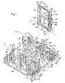
- FIG. 1 there is shown a device for mounting electrical equipment comprising a base 100 forming the bottom of a housing for electrical equipment.
- This base 100 is in the form of a plate and allows the fixing of the housing to any wall.
- this base 100 is of square shape and is intended to receive a closure cap (not shown) whose peripheral edge adapts to the peripheral edge 101 of said base 100.
- the base 100 is intended to be mounted on a wall (not shown) at the outlet of a built-in electrical installation or along a trunking cable or electrical conductors (not shown).
- It can also be a housing to project on a wall, powered by cables, with or without conduit, also placed projecting on the wall.
- This base 100 includes, in the right of each housing for electrical equipment, pre-cuts 109 arranged in a circle.
- this base 100 When this base 100 is intended to be mounted at the output of a built-in electrical installation, the precuts 109 are broken by the installer so as to create entry openings of conductors or electrical cables inside the housing in order to their connection to the electrical equipment concerned and placed in said housing.
- These arrangements comprise, on the one hand, a platform 110 extending in the plane of said base 100 projecting from its edge, and, on the other hand, two columns 111 rising perpendicular to the plane of the base 100, disposed on either side of said platform 110 and having a longitudinal opening forming a groove means for the establishment of awning not shown.
- the base 100 forming the bottom of the housing further comprises, at its four corners, four holes 104 for fixing the housing to a wall.
- Each hole 104 has an elongated shape, here an oblong shape. These holes 104 are arranged in pairs on the same line so that they extend towards one another.
- each of these holes is intended to engage a housing fixing member adapted to come to anchor in the wall considered.
- each hole 104 belongs to a stud 105 attached to the base 100 of the housing by a flexible connection 106 allowing a slight offset of the hole 104 parallel to the plane of the base 100, in a direction transverse to the direction of elongation of the hole, relative to at a stable home position.
- Each flexible connection 106 connecting a stud 105 to the base 100 is constituted by a flexible tongue capable of bending to shift said stud to the left or to the right of its original stable position.
- Each stud 105 comes from formation with each associated flexible tongue 106 which itself comes from forming by molding a plastic material with the base 100.
- each stud 105 is located at a free end of said flexible tongue constituting the flexible connection 106 extending freely inwardly of the base 100 in an opening 107 provided in said base.
- each opening 107 has a shape generally ⁇ , the edge of the opening 107, to which is attached the pad 105 by the flexible connection 106, being parallel to an edge of the base 100.
- each stud 105 carries, on either side of the flexible link 106, stops 108 which extend in a direction transverse to the direction of elongation of the corresponding hole 104 in a rectangular part of the opening 107.
- the stops 108 are formed with each stud 105 by molding a plastic material.
- These stops 108 are able to bear against a portion of the base 100 of the housing, to press the base 100 against the wall.
- the device for mounting electrical equipment comprises, in addition to said base, a support for electrical equipment 200 (see FIG. figure 1 ).
- the base 100 projects posts 112, and said support 200 and the uprights 112 comprise complementary assembly means 208, 209, 114 for mounting said support 200 at the free end of each upright 112.
- the base 100 projects two sets of four columns 112 forming uprights which carry at their top said assembly means 114 for mounting said electrical equipment support 200.
- the columns 112 are arranged at the four corners of a rectangle and are connected two by two to one another by partitions 113, said partitions 113 delimiting between them said housings for electrical equipment.
- Each set of four columns 112 accommodates a support of electrical equipment 200 which here has a rectangular shape adjusted to the positioning of the corresponding columns 112.
- each support of electrical equipment 200 is in the form of a rectangular frame with two windows 203 with longitudinal uprights 201 connected by cross members 202.
- Said electrical equipment support 200 has a front face, turned away from the base 100, which is substantially flat.
- An electrical apparatus (not shown) is intended to be attached in each of the windows 203 of said electrical equipment support 200.
- each support of electrical equipment 200 there is provided said assembly means 208, 209, each of these assembly means cooperating with the assembly means provided at a top of a column 112 projecting by the base 100.
- the complementary assembly means provided on the columns 112 of the base 100 and on the support of electrical equipment 200 comprise means for pivoting said support 200 relative to said columns 112 forming uprights around an axis X which extends parallel to the plane of said front face of said support 200.
- each support of electrical equipment 200 are identical so that said support is articulated on each pair of columns 112 vis-à-vis.
- each support of electrical equipment 200 can be articulated from right to left or from left to right depending on the access needs of the installer.
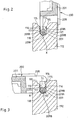
- said complementary assembly means comprise, here, at each corner of the electrical equipment support 200, a shaft 209 and, on each column 112, a housing 114 for receiving said shaft 209, this housing 114 having a rounded bottom 118 on which the outer surface 209A of the shaft 209 slides to pivot.
- the support of electrical equipment 200 comprises, at each of its corners, a housing, and that the shaft is carried by the top of a projecting column. said base.
- the shafts 209 of said support 200 are aligned in pairs along the axis X of pivoting thereof.
- each shaft 209 of the electrical equipment support 200 extends transversely in a window 208.
- each shaft 209 has a circular section truncated by two parallel flats 209B. This configuration of each shaft 209 facilitates its introduction into each housing 114.
- each shaft 209 has a circular section.
- each column 112 advantageously has a U-shaped, with a rounded bottom 118 from which rise two parallel side walls 117, the width l is slightly greater than the largest diameter of the section of the corresponding shaft 209.
- each housing 114 opens outwardly through a flared inlet mouth 115 facilitating the introduction of each shaft into said housing.
- the housing 114 has a width l1 slightly smaller than the largest diameter of the section of said shaft 209.
- said complementary assembly means provided at the vertices of the columns 112 of the base 100 and on the support of electrical equipment 200, form latching means of said support 200 on said columns 112.
- the support of electrical equipment 200 is engaged in two first columns 112 being positioned perpendicular to the base 100 so that the flats 209B of its shafts 209 are aligned with the longitudinal axis of the corresponding housing 114.
- each shaft 209 facilitates its introduction into the corresponding housing 114.
- the electrical equipment support 200 is pivoted about the axis X in the direction of the two other columns 112 arranged vis-à-vis the first two columns 112 to be positioned parallel to the base 100, and the other trees 209, carried by the support of electrical equipment opposite to those already engaged in the first housing 114, engage by force or snap in the housing 114 of the other corresponding columns 112.
- said other shafts 209 of said support 200 are facing said corresponding housing 114 with their flats 209B extending transversely to the longitudinal axis of said housing (as shown in FIG. figure 3 ).
- the largest width of each shaft 209 must be forced through the smaller width 11 of the corresponding housing 114.
- the support of electrical equipment 200 comprises on a rear face turned towards the base 100, along one of its longitudinal sides, that is to say on one of its longitudinal uprights 201, two parallel walls 205 projecting defining a housing 204 for receiving a lighting diode 300 forming a light indicator of the operation of the electrical equipment mechanism or mechanisms carried by said support 200.
- the housing 204 is also provided with means for retaining said diode 300.
- the bottom of the housing 204 comprises, in line with the location of said diode 300, an orifice 207 opening on the front face of said support 200 turned away from the base 100.
- the light rays emitted by the lighting diode 300 pass through the orifice 207 to be visible from the outside during the operation of the electrical equipment concerned.
- the retaining means of the lighting diode 300 are preferably latching means constituted here by turrets 206 positioned at the end of the two parallel walls 205 delimiting the housing 204 of the lighting diode 300.
- latching means constituted here by turrets 206 positioned at the end of the two parallel walls 205 delimiting the housing 204 of the lighting diode 300.
- turrets 206 are provided at each end of said walls 205 for mounting on the right or left side of the lighting diode 300.
- an installer can have access to the rear of the equipment mechanisms carried by said support 200 by disengaging the latter at one end and pivoting at its other end into the housing 114 to position it perpendicularly to the base 100 (see figure 2 ), or even 180 ° relative to said base.
- This pivotal mounting can also advantageously allow access to the lighting diode 300 to replace it.
- the support of electrical equipment 200 being provided to support two equipment mechanisms, the pivoting to the right or to the left of the support 200 is particularly advantageous for access to one or the other of the equipment mechanisms that he supports.
Landscapes
- Engineering & Computer Science (AREA)
- Architecture (AREA)
- Civil Engineering (AREA)
- Structural Engineering (AREA)
- Casings For Electric Apparatus (AREA)
Claims (11)
- Vorrichtung zur Montage elektrischer Installationsgeräte, die einen Installationsgeräteträger (200) mit einer allgemein ebenen Vorderseite und einen Sockel (100) umfasst, der vorstehend wenigstens eine Stütze (112) aufweist, wobei der Träger (200) und die Stütze (112) komplementäre Verbindungsmittel (208, 209; 114) zur Montage des Trägers (200) am freien Ende der Stütze (112) aufweisen,
dadurch gekennzeichnet, dass die komplementären Verbindungsmittel Mittel (209A, 118) zum Schwenken des Trägers (200) bezüglich der Stütze (112) um eine parallel zur Ebene der Vorderseite des Trägers (200) verlaufenden Achse (X) umfassen. - Montagevorrichtung nach Anspruch 1,
dadurch gekennzeichnet, dass die komplementären Verbindungsmittel Mittel (209, 115, 116) zum Einrasten des Trägers (200) auf der Stütze (112) umfassen. - Montagevorrichtung nach einem der Ansprüche 1 oder 2, wobei der Installationsgeräteträger (200) eine rechteckige Form aufweist,
dadurch gekennzeichnet, dass der Träger (200) an seinen vier Ecken die Verbindungsmittel (209, 209) aufweist und der Sockel (100) vorstehend wenigstens zwei sich gegenüberliegende Stützen (112) trägt, die an ihrem freien Ende mit den komplementären Verbindungsmitteln (114) versehen sind, derart, dass der Träger (200) auf den beiden sich gegenüberliegenden Stützen (112) jeweils gelenkig lagert. - Montagevorrichtung nach einem der Ansprüche 1 bis 3,
dadurch gekennzeichnet, dass der Sockel (100) vorstehend vier Stützen bildende Pfeiler (112) trägt, die an ihrem Scheitelpunkt mit den Verbindungsmitteln (114) zur schwenkbaren Montage des Installationsgeräteträgers (200) versehen sind. - Montagevorrichtung nach einem der Ansprüche 1 bis 4,
dadurch gekennzeichnet, dass die komplementären Verbindungsmittel auf dem einen der beiden Teile, die den Installationsgeräteträger (200) und die Stütze (112) bilden, eine Welle (209) und auf dem anderen der beiden Teile eine Lagerung (114) zur Aufnahme der Welle (209) umfassen, wobei die Lagerung (114) einen abgerundeten Boden (118) aufweist, auf dem die Außenseite (209A) der Welle (209) zum Schwenken gleitet. - Montagevorrichtung nach Anspruch 5,
dadurch gekennzeichnet, dass die Welle (209) einen runden Querschnitt aufweist. - Montagevorrichtung nach Anspruch 5,
dadurch gekennzeichnet, dass die Welle (209) einen durch zwei parallele Abflachungen (209A) abgestumpften runden Querschnitt aufweist. - Montagevorrichtung nach einem der Ansprüche 5 bis 7,
dadurch gekennzeichnet, dass die Welle (209) in einer in dem Teil vorgesehenen Öffnung (208) quer verläuft. - Montagevorrichtung nach einem der Ansprüche 5 bis 8,
dadurch gekennzeichnet, dass die Lagerung (114) die Form eines U hat, dessen Breite (l) geringfügig größer ist als der größte Durchmesser des Querschnitts der Welle (209), und sich durch eine erweiterte Eingangsmündung (115) nach außen öffnet, wobei die Breite (11) der Lagerung (114) am Übergang zur Eingangsmündung (115) geringfügig kleiner ist als der größte Durchmesser des Querschnitts der Welle (209). - Montagevorrichtung nach einem der Ansprüche 1 bis 9,
dadurch gekennzeichnet, dass der Installationsgeräteträger (200) auf einer dem Sockel (100) zugewandten Seite entlang einer seiner Längsseiten eine Lagerung (204) zur Aufnahme einer Leuchtdiode (300) und von Mitteln zum Halten der Diode (300) umfasst, wobei der Boden der Lagerung (204) senkrecht zur Anordnung der Diode (300) mit einer Öffnung (207) durchbohrt ist, die in die dem Sockel abgewandte Vorderseite des Trägers (200) mündet. - Montagevorrichtung nach Anspruch 10,
dadurch gekennzeichnet, dass die Mittel zum Halten der Leuchtdiode (300) Rastmittel (206) sind.
Applications Claiming Priority (2)
| Application Number | Priority Date | Filing Date | Title |
|---|---|---|---|
| FR0202894A FR2837031B1 (fr) | 2002-03-07 | 2002-03-07 | Dispositif de montage d'appareillages electriques a support pivotant |
| FR0202894 | 2002-03-07 |
Publications (2)
| Publication Number | Publication Date |
|---|---|
| EP1343236A1 EP1343236A1 (de) | 2003-09-10 |
| EP1343236B1 true EP1343236B1 (de) | 2017-05-10 |
Family
ID=27741455
Family Applications (1)
| Application Number | Title | Priority Date | Filing Date |
|---|---|---|---|
| EP03290556.4A Expired - Lifetime EP1343236B1 (de) | 2002-03-07 | 2003-03-07 | Vorrichtung zum Montieren von elektrischen Apparaten mit einem Scharnier |
Country Status (3)
| Country | Link |
|---|---|
| EP (1) | EP1343236B1 (de) |
| ES (1) | ES2636990T3 (de) |
| FR (1) | FR2837031B1 (de) |
Families Citing this family (1)
| Publication number | Priority date | Publication date | Assignee | Title |
|---|---|---|---|---|
| IT1391945B1 (it) | 2008-11-18 | 2012-02-02 | Gewiss Spa | Scatola di derivazione per impianti elettrici e simili |
Family Cites Families (3)
| Publication number | Priority date | Publication date | Assignee | Title |
|---|---|---|---|---|
| DE4103957A1 (de) * | 1991-02-09 | 1992-08-13 | Kleinhuis Hermann Gmbh | Kabelkanal, wie installationskanal |
| DE29617895U1 (de) * | 1996-10-15 | 1997-01-02 | Trilux-Lenze Gmbh + Co Kg, 59759 Arnsberg | Versorgungsbalken für die Intensivpflege |
| DE29918680U1 (de) * | 1999-10-23 | 2001-03-08 | Tehalit GmbH, 67716 Heltersberg | Geräteträger für Sockelleisten-Installationskanäle |
-
2002
- 2002-03-07 FR FR0202894A patent/FR2837031B1/fr not_active Expired - Fee Related
-
2003
- 2003-03-07 ES ES03290556.4T patent/ES2636990T3/es not_active Expired - Lifetime
- 2003-03-07 EP EP03290556.4A patent/EP1343236B1/de not_active Expired - Lifetime
Also Published As
| Publication number | Publication date |
|---|---|
| FR2837031B1 (fr) | 2004-07-09 |
| FR2837031A1 (fr) | 2003-09-12 |
| ES2636990T3 (es) | 2017-10-10 |
| EP1343236A1 (de) | 2003-09-10 |
Similar Documents
| Publication | Publication Date | Title |
|---|---|---|
| FR2978509A1 (fr) | Accessoire de blocage d'un support d'appareillage dans une paroi creuse | |
| FR2738676A1 (fr) | Appareil electrique a bornes de raccordement protegees par un diaphragme | |
| EP1106774B1 (de) | Vorrichtung zum Fixieren eines Antriebs, und Betätigungsmechanismus einer Schliess- oder Sonnenschutzeinrichtung mit solcher Vorrichtung | |
| FR3105559A1 (fr) | Boîte électrique et appareillage électrique associé | |
| EP0911932B1 (de) | Montageadapter für nichtquadratisch geformtes elektrisches Apparat | |
| EP1343236A1 (de) | Vorrichtung zum Montieren von elektrischen Apparaten mit einem Scharnier | |
| FR2688897A1 (fr) | Prise optique. | |
| EP3345269B1 (de) | Dose zum einbau in eine wand | |
| EP0940349B1 (de) | Dose bestehend aus lösbaren, schwenkbaren Elementen, insbesondere für Leuchten | |
| FR2948825A1 (fr) | Boite electrique de sol a moyens de montage rapide d'un module de connexion electrique | |
| FR2615052A1 (fr) | Enrouleur, en particulier pour cable electrique | |
| EP3255732B1 (de) | Elektrische verbindungsklemme, die einen verbindungshebel umfasst, und entsprechende elektrische geräte | |
| EP0744088A1 (de) | Elektrische stecker in englischer ausführung | |
| FR2810467A1 (fr) | Dispositif de montage d'un appareil electrique sur un conduit de cablage | |
| EP1724888A1 (de) | Modulares Gehäuse für elektrische Geräte | |
| WO2021122043A1 (fr) | Boite electrique en deux parties | |
| EP2320532B1 (de) | Vorrichtung zur Montage eines Pfostens am hinteren Teil eines Stromverteilungskastens, und mit einer solchen Vorrichtung ausgestatteter Stromverteilungskasten | |
| EP0739070B1 (de) | Elektrische Verbindungsvorrichtung für die Kupplung eines Elektrogerätes am Netz | |
| FR2902239A1 (fr) | Borne de connexion auto-denudante d'un conducteur electrique isole et appareillage elelctrique comportant une telle borne | |
| EP1343238B1 (de) | Dose für elektrisches Gerät mit biegsamer Befestigung | |
| FR2819949A1 (fr) | Agencement d'un dispositif de connexion electrique d'un luminaire encastrable | |
| EP1385244B1 (de) | Dose für elektrisches Gerät zur Montage entlang eines Kabelkanals | |
| FR2842032A1 (fr) | Entretoise et boitier comportant cette entretoise | |
| BE1016892A3 (fr) | Support d'appareillage electrique mixte avec vis de fixation decalees dans l'epaisseur dudit support, ensemble electrique comprenant un tel support, et appareillage comprenant une boite a encastrer, et un tel ensemble electrique. | |
| FR3130063A1 (fr) | Bloc autonome d’éclairage de sécurité |
Legal Events
| Date | Code | Title | Description |
|---|---|---|---|
| PUAI | Public reference made under article 153(3) epc to a published international application that has entered the european phase |
Free format text: ORIGINAL CODE: 0009012 |
|
| AK | Designated contracting states |
Kind code of ref document: A1 Designated state(s): AT BE BG CH CY CZ DE DK EE ES FI FR GB GR HU IE IT LI LU MC NL PT SE SI SK TR |
|
| AX | Request for extension of the european patent |
Extension state: AL LT LV MK RO |
|
| 17P | Request for examination filed |
Effective date: 20031122 |
|
| AKX | Designation fees paid |
Designated state(s): DE ES IT PT |
|
| RAP1 | Party data changed (applicant data changed or rights of an application transferred) |
Owner name: LEGRAND FRANCE Owner name: LEGRAND SNC |
|
| GRAP | Despatch of communication of intention to grant a patent |
Free format text: ORIGINAL CODE: EPIDOSNIGR1 |
|
| STAA | Information on the status of an ep patent application or granted ep patent |
Free format text: STATUS: GRANT OF PATENT IS INTENDED |
|
| INTG | Intention to grant announced |
Effective date: 20161123 |
|
| GRAS | Grant fee paid |
Free format text: ORIGINAL CODE: EPIDOSNIGR3 |
|
| GRAA | (expected) grant |
Free format text: ORIGINAL CODE: 0009210 |
|
| STAA | Information on the status of an ep patent application or granted ep patent |
Free format text: STATUS: THE PATENT HAS BEEN GRANTED |
|
| AK | Designated contracting states |
Kind code of ref document: B1 Designated state(s): DE ES IT PT |
|
| REG | Reference to a national code |
Ref country code: DE Ref legal event code: R096 Ref document number: 60350210 Country of ref document: DE |
|
| REG | Reference to a national code |
Ref country code: ES Ref legal event code: FG2A Ref document number: 2636990 Country of ref document: ES Kind code of ref document: T3 Effective date: 20171010 |
|
| REG | Reference to a national code |
Ref country code: DE Ref legal event code: R097 Ref document number: 60350210 Country of ref document: DE |
|
| PG25 | Lapsed in a contracting state [announced via postgrant information from national office to epo] |
Ref country code: IT Free format text: LAPSE BECAUSE OF FAILURE TO SUBMIT A TRANSLATION OF THE DESCRIPTION OR TO PAY THE FEE WITHIN THE PRESCRIBED TIME-LIMIT Effective date: 20170510 |
|
| PLBE | No opposition filed within time limit |
Free format text: ORIGINAL CODE: 0009261 |
|
| STAA | Information on the status of an ep patent application or granted ep patent |
Free format text: STATUS: NO OPPOSITION FILED WITHIN TIME LIMIT |
|
| 26N | No opposition filed |
Effective date: 20180213 |
|
| REG | Reference to a national code |
Ref country code: DE Ref legal event code: R119 Ref document number: 60350210 Country of ref document: DE |
|
| PG25 | Lapsed in a contracting state [announced via postgrant information from national office to epo] |
Ref country code: DE Free format text: LAPSE BECAUSE OF NON-PAYMENT OF DUE FEES Effective date: 20181002 |
|
| PG25 | Lapsed in a contracting state [announced via postgrant information from national office to epo] |
Ref country code: PT Free format text: LAPSE BECAUSE OF FAILURE TO SUBMIT A TRANSLATION OF THE DESCRIPTION OR TO PAY THE FEE WITHIN THE PRESCRIBED TIME-LIMIT Effective date: 20170510 |
|
| PGFP | Annual fee paid to national office [announced via postgrant information from national office to epo] |
Ref country code: ES Payment date: 20200423 Year of fee payment: 18 |
|
| REG | Reference to a national code |
Ref country code: ES Ref legal event code: FD2A Effective date: 20220523 |
|
| PG25 | Lapsed in a contracting state [announced via postgrant information from national office to epo] |
Ref country code: ES Free format text: LAPSE BECAUSE OF NON-PAYMENT OF DUE FEES Effective date: 20210308 |