EP1343237B1 - Elektrisches Gerät - Google Patents
Elektrisches Gerät Download PDFInfo
- Publication number
- EP1343237B1 EP1343237B1 EP03004621A EP03004621A EP1343237B1 EP 1343237 B1 EP1343237 B1 EP 1343237B1 EP 03004621 A EP03004621 A EP 03004621A EP 03004621 A EP03004621 A EP 03004621A EP 1343237 B1 EP1343237 B1 EP 1343237B1
- Authority
- EP
- European Patent Office
- Prior art keywords
- electrical device
- housing
- latching
- carrier member
- floor
- Prior art date
- Legal status (The legal status is an assumption and is not a legal conclusion. Google has not performed a legal analysis and makes no representation as to the accuracy of the status listed.)
- Expired - Lifetime
Links
Images


Classifications
-
- H—ELECTRICITY
- H02—GENERATION; CONVERSION OR DISTRIBUTION OF ELECTRIC POWER
- H02G—INSTALLATION OF ELECTRIC CABLES OR LINES, OR OF COMBINED OPTICAL AND ELECTRIC CABLES OR LINES
- H02G3/00—Installations of electric cables or lines or protective tubing therefor in or on buildings, equivalent structures or vehicles
- H02G3/02—Details
- H02G3/08—Distribution boxes; Connection or junction boxes
- H02G3/10—Distribution boxes; Connection or junction boxes for surface mounting on a wall
Definitions
- the present invention relates to an electrical device with a housing and with disposed within the housing in a terminal space area electrical Connection elements for externally supplied connection conductor.
- the present invention has for its object to provide an electrical device of called type to create, in which the outer leads to simpler and comfortable manner can be connected to the connection elements.
- connection elements within of the housing are positionally variable so that they come from a device operating position enlarging the connection space area to a connection position and back are transferable.
- This advantageous embodiment thus allows the terminal compartment area enlarge, so that the connecting conductor containing outer cable on easy way is insertable and within the enlarged terminal space area because of the greater range of motion the cable is stripped and the individual Conductor stripped stripped and under appropriate bending deformation of the Connection elements can be connected. After the actual electrical connection then the connection elements under appropriate Re-reduction of the terminal room area as well as under further Bending deformation of the lead moved back to the device use position.
- an electrical device 1 is for Installation on a - formed in particular by a vertical wall - Mounting surface 2 (see Fig. 6) provided, d. H. for so-called surface-mounting.
- a vertical wall - Mounting surface 2 (see Fig. 6) provided, d. H. for so-called surface-mounting.
- it can also be a flush-mounted device.
- connection elements 8 for example in the form of Conductor terminals arranged for connection of leads 10.
- a connecting cable 12 (Fig. 6) laid under plaster.
- This connection cable 12 includes the leads 10 and is connected to a terminal end by a cable insertion opening 14 inserted into the terminal space portion 6 of the housing 4 to in To connect this area, the connection conductor 10 to the connection elements 8.
- the connecting elements 8 are inside the housing 4 positionable such that it can be moved from a device operating position (FIGS. 3 and 5a, b) enlarging the connection space region 6 into a connection position (FIGS 4, 5c and 6) can be transferred.
- a device operating position FIGS. 3 and 5a, b
- a connection position FIGS 4, 5c and 6
- Connecting the lead 10 to the connecting elements 8 essential, since the Fitter gets a greater freedom of movement.
- connection elements 8 with the connected Anschlußleitem back in the operating position of the device 1 are transferred, under appropriate Bending deformation of the connecting conductor 10th
- the connecting elements 8 - preferably together with other equipment components - attached to a support member 16, wherein the Carrier element 16 slidably guided in the housing 4 and at least in the Device operating position of the connecting elements 8 is releasably locked.
- the carrier element 16 is formed by a printed circuit board according to FIGS. 3 and 4 in FIG lateral, rail-like guide profiles 18 of the housing 4 slidably guided is.
- Figures 3 to 5 are for releasably locking the Carrier element 16 locking means 20 is provided.
- preferred Embodiment is as a locking means 20 at least one resilient locking arm 22nd provided (see in particular Fig.
- the recess 26 is advantageous as a in the direction of displacement of the support member 16 extending slot formed (Figs. 3 and 4), wherein the locking arm 22 to parallel in particular below the carrier element 16 between this and a housing bottom wall 28th runs.
- the latching arm 22 at a free, on the latch 24th Outwardly extending end preferably a button-like, in the recess 26th engaging operating piece 30.
- the locking arm 22 engages in the locked use position with the latch 24 so in the recess 26 that a shift of Carrier element 16 is locked in the terminal position shown in FIG. 5c.
- the Latch 24 and the actuating piece 30 in adaptation to the length of the slot locking recess 26 spaced apart such that the carrier element 16 is fixed in the other direction of displacement.
- the support member 16 safely held in its operating position.
- the locking arm 22 via the actuating piece 30 are pressed in the direction of arrow 32 down to the so To bring locking lug 24 out of engagement from the slot-Raviausström supraung 26. Subsequently, the carrier element 16 together with in Fig.
- the cable insertion opening 14 is arranged in the region of the bottom wall 28 and opens inside the housing in the terminal compartment area 6.
- the bottom wall 28 pointing on its to the mounting surface 2 Outside at least one channel-shaped receiving recess 38 for the Connecting cable 12 has.
- the cable insertion opening 14 is within the Area of the receiving recess 38.
- the housing 4 or the bottom wall 28 an elongated, preferably substantially rectangular basic shape, wherein the channel-shaped receiving recess 38 in a straight line in the longitudinal direction of the bottom wall 28 and preferably approximately centrally substantially over its entire extent runs.
- the cable insertion opening 14 is in an end region of the channel-shaped Receiving well 38 arranged, and indeed in accordance with FIG. 6 in particular in one obliquely extending between the bottom wall 28 and a recess bottom 40 Wall section 42.
- the channel-like receiving recess 38 is preferred at one end directly into the cable insertion opening 14 via.
- the device 1 can by this advantageous embodiment simple way in double arrow 44 (course direction of the channel-like Receiving recess 38) on the mounting surface 2 relative to the location of Wall outlet of the connecting cable 12 are aligned, in which case the Connecting cable 12 more or less far through a corresponding section of the Receiving recess 38 extends and inside the housing within the Terminal space area 6 stripped directly behind the insertion opening 8 to the terminal can be.
- the wall section 42 at an angle of preferably about 20 ° to 50 ° obliquely to Bottom wall 28 extends that passing through the receiving recess 38 Connecting cable 12 under an approximately right-angled bend through the insertion opening 14 can be performed.
- a splash water seal in Area of the insertion opening 14 is provided.
- the insertion opening 14th preferably in a separate, seated in the housing 4 sealing member 46th formed a splash-proof cable entry (according to IP44) guaranteed.
- the sealing element 46 from a holding portion 48 for holding connection with the housing 4 and from a sleeve-like, the cable insertion opening 14 enclosing sealing portion 50th
- This spout-like sealing portion 50 forms an elastic lip seal for circumferential support on the connecting cable 12.
- the insertion opening 14th circular and with an initially smaller diameter than the connecting cable 10 trained.
- the sealing element 46 is preferably in one piece as Two-component molding made of plastic. In this case, there are the holding section 48 of a relatively stronger, more dimensionally stable plastic material and the sealing portion 50 of a relatively flexible, elastic plastic material.
- the sealing element 46 can advantageously in the region of the holding portion 48th be formed integrally with the latching arms 22 (Fig. 5).
- the invention is not limited to the illustrated and described embodiment limited, but also includes all the same in the context of the invention Versions. So it can be a basically arbitrary device, if also in the preferred embodiment, the device 1 in a flat, compact design for example, is designed as a door station of a home communication system and a key device 52 (bell buttons) and a speaker device 54 ( Figures 1, 3 and 4).
Landscapes
- Engineering & Computer Science (AREA)
- Architecture (AREA)
- Civil Engineering (AREA)
- Structural Engineering (AREA)
- Connections By Means Of Piercing Elements, Nuts, Or Screws (AREA)
- Multi-Conductor Connections (AREA)
- Connector Housings Or Holding Contact Members (AREA)
- Electrical Discharge Machining, Electrochemical Machining, And Combined Machining (AREA)
- Power Steering Mechanism (AREA)
- Installation Of Indoor Wiring (AREA)
- Connections Arranged To Contact A Plurality Of Conductors (AREA)
Description
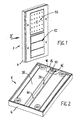
- Fig. 1
- eine Perspektivansicht einer möglichen Ausführung eines erfindungsgemäßen elektrischen Gerätes auf dessen Vorderseite,
- Fig. 2
- eine vergrößerte Perspektivansicht auf die Rück- bzw. Unterseite des Gerätes in Pfeilrichtung II gemäß Fig. 1,
- Fig. 3
- eine Perspektivansicht des Gerätes in einem geöffnetem Zustand zur Einsicht auf den Anschlußraumbereich, und zwar in der eigentlichen Geräte-Gebrauchs-bzw. Betriebsposition,
- Fig. 4
- eine Ansicht wie in Fig. 3, jedoch in einem anschlußbereiten Zustand in der Anschlußposition,
- Fig. 5 a bis 5c
- vergrößerte Schnittdarstellungen in der Ebene V - V gemäß Fig. 3 in unterschiedlichen Zuständen und
- Fig. 6
- eine vergrößerte Teilschnittdarstellung in der Ebene VI - VI gemäß Fig. 4.
Claims (16)
- Elektrisches Gerät (1) mit einem Gehäuse (4) und mit innerhalb des Gehäuses (4) in einem Anschlußraumbereich (6) angeordneten elektrischen Anschlußelementen (8) für von außen zuzuführende Anschlußleiter (10),
dadurch gekennzeichnet, dass die Anschlußelemente (8) innerhalb des Gehäuses (4) derart lageveränderbar sind, dass sie aus einer Geräte-Betriebsposition unter Vergrößerung des Anschlußraumbereichs (6) in eine Anschlußposition und zurück überführbar sind. - Elektrisches Gerät nach Anspruch 1,
dadurch gekennzeichnet, dass die Anschlußelemente (8) - vorzugsweise zusammen mit sonstigen Gerätebestandteilen (52, 54) - an einem Trägerelement (16) befestigt sind, wobei das Trägerelement (16) verschiebbar in dem Gehäuse (4) geführt und zumindest in der Geräte-Betriebsposition der Anschlußelemente (8) lösbar arretiert ist. - Elektrisches Gerät nach Anspruch 2,
dadurch gekennzeichnet, dass das Trägerelement (16) von einer Leiterplatte gebildet ist, die in seitlichen, schienenartigen Führungsprofilen (18) des Gehäuses (4) verschiebbar geführt ist. - Elektrisches Gerät nach Anspruch 2 oder 3,
dadurch gekennzeichnet, dass zum lösbaren Arretieren des Trägerelementes (16) Rastmittel (20) vorgesehen sind. - Elektrisches Gerät nach Anspruch 4,
dadurch gekennzeichnet, dass als Rastmittel (20) mindestens ein federelastischer Rastarm (22) vorgesehen ist, der einendig im Gehäuse (4) befestigt ist und in der Gebrauchsposition mit einer Rastnase (24) in eine Rastausnehmung (26) des Trägerelementes (16) eingreift. - Elektrisches Gerät nach Anspruch 5,
dadurch gekennzeichnet, dass die Rastausnehmung (26) als ein sich in Verschieberichtung (34, 36) des Trägerelementes (16) erstreckendes Langloch ausgebildet ist, wobei der Rastarm (22) dazu parallel insbesondere unterhalb des Trägerelementes (16) zwischen diesem und einer Gehäuse-Bodenwandung (28) verläuft. - Elektrisches Gerät nach Anspruch 5 oder 6,
dadurch gekennzeichnet, dass der Rastarm (22) an einem freien, sich über die Rastnase (24) hinaus erstreckenden Ende ein vorzugsweise knopfartiges Betätigungsstück (30) aufweist, welches derart in die Rastausnehmung (26) eingreift, dass durch Druck auf das Betätigungsstück (30) und dadurch bewirkte elastische Verformung des Rastarms (22) die Rastnase (24) außer Eingriff aus der Rastausnehmung (26) bringbar ist. - Elektrisches Gerät nach Anspruch 7,
dadurch gekennzeichnet, dass die Rastnase (24) und das Betätigungsstück (30) in Anpassung an die Länge der Langloch-Rastausnehmung (26) derart voneinander beabstandet sind, dass das Trägerelement (16) in einer eingreifenden Ruhelage des Rastarms (22) in der Betriebsposition in beiden Richtungen fixiert ist. - Elektrisches Gerät nach einem der Ansprüche 4 bis 8,
dadurch gekennzeichnet, dass auf beiden Seiten des Trägerelementes (16) jeweils gleichartige Rastmittel (20) vorgesehen sind. - Elektrisches Gerät nach einem der Ansprüche 1 bis 9,
gekennzeichnet durch eine Ausführung als Aufputz-Gerät zur Montage auf einer Montagefläche (2), wobei das Gehäuse (4) eine der Montagefläche (2) zuzukehrende Bodenwandung (28) mit einer gehäuseinnenseitig in den Anschlußraumbereich (6) mündenden Einführöffnung (14) für ein. die Anschlußleiter (10) enthaltendes, äußeres, von der Montagefläche (2) her zuzuführendes Anschluß-Kabel (12) aufweist. - Elektrisches Gerät nach Anspruch 10,
dadurch gekennzeichnet, dass die Bodenwandung (28) auf ihrer zu der Montagefläche (2) weisenden Außenseite eine kanalförmige Aufnahmevertiefung (38) für das Anschlußkabel (12) aufweist, wobei die Kabel-Einführöffnung (14) innerhalb des Bereichs der Aufnahmevertiefung (38) liegt. - Elektrisches Gerät nach Anspruch 11,
dadurch gekennzeichnet, dass das Gehäuse (4) bzw. die Bodenwandung (28) eine längliche, bevorzugt im Wesentlichen rechteckige Grundform aufweist, wobei die kanalförmige Aufnahmevertiefung (38) insbesondere geradlinig in Längsrichtung der Bodenwandung (28) und bevorzugt etwa mittig im Wesentlichen über deren gesamte Erstreckung verläuft. - Elektrisches Gerät nach Anspruch 11 oder 12,
dadurch gekennzeichnet, dass die Kabel-Einführöffnung (14) in einem Endbereich der kanalförmigen Aufnahmevertiefung (38), vorzugsweise in einem insbesondere schräg zwischen der Bodenwandung (28) und einem Vertiefungsgrund (40) verlaufenden Wandungsabschnitt (42) angeordnet ist. - Elektrisches Gerät nach einem der Ansprüche 11 bis 13,
dadurch gekennzeichnet, dass die Kabel-Einführöffnung (14) eine Spritzwasser-Abdichtung aufweist und dazu insbesondere in einem separaten, im Gehäuse (4) sitzenden Dichtungselement (46) gebildet ist. - Elektrisches Gerät nach Anspruch 14,
dadurch gekennzeichnet, dass das Dichtungselement (46) aus einem Halteabschnitt (48) zur Halteverbindung mit dem Gehäuse (4) und einem insbesondere tüllenartigen, die Kabel-Einführöffnung (14) umschließenden Dichtabschnitt (50) besteht. - Elektrisches Gerät nach Anspruch 15,
dadurch gekennzeichnet, dass das Dichtungselement (46) einteilig als Zweikomponenten-Formteil aus Kunststoff gebildet ist, wobei der Halteabschnitt (48) aus einem relativ festeren, formstabileren Kunststoffmaterial und der Dichtabschitt (50) aus einem relativ flexibleren, elastischen Kunststoffmaterial bestehen.
Applications Claiming Priority (2)
| Application Number | Priority Date | Filing Date | Title |
|---|---|---|---|
| DE20203847U | 2002-03-09 | ||
| DE20203847U DE20203847U1 (de) | 2002-03-09 | 2002-03-09 | Elektrisches Gerät |
Publications (2)
| Publication Number | Publication Date |
|---|---|
| EP1343237A1 EP1343237A1 (de) | 2003-09-10 |
| EP1343237B1 true EP1343237B1 (de) | 2004-05-12 |
Family
ID=7968801
Family Applications (1)
| Application Number | Title | Priority Date | Filing Date |
|---|---|---|---|
| EP03004621A Expired - Lifetime EP1343237B1 (de) | 2002-03-09 | 2003-03-03 | Elektrisches Gerät |
Country Status (3)
| Country | Link |
|---|---|
| EP (1) | EP1343237B1 (de) |
| AT (1) | ATE266905T1 (de) |
| DE (2) | DE20203847U1 (de) |
Families Citing this family (2)
| Publication number | Priority date | Publication date | Assignee | Title |
|---|---|---|---|---|
| FR2851970B1 (fr) * | 2003-03-05 | 2006-03-17 | Rehau Sa | Dispositif de verrouillage longitudinal de securite pour piece rapportee sur la tole de carrosserie d'un vehicule routier |
| DE10340761B3 (de) * | 2003-09-02 | 2005-07-07 | Ritto Gmbh & Co. Kg | Türstadion mit geschlossener Bedienerfläche |
Family Cites Families (2)
| Publication number | Priority date | Publication date | Assignee | Title |
|---|---|---|---|---|
| JPH0793505B2 (ja) * | 1990-11-09 | 1995-10-09 | 松下電器産業株式会社 | ロック解除機構付ツメ状ロック装置 |
| JP3865278B2 (ja) * | 1998-03-11 | 2007-01-10 | 矢崎総業株式会社 | 自動車ドア用コネクタの接続構造 |
-
2002
- 2002-03-09 DE DE20203847U patent/DE20203847U1/de not_active Expired - Lifetime
-
2003
- 2003-03-03 EP EP03004621A patent/EP1343237B1/de not_active Expired - Lifetime
- 2003-03-03 AT AT03004621T patent/ATE266905T1/de active
- 2003-03-03 DE DE50300013T patent/DE50300013D1/de not_active Expired - Lifetime
Also Published As
| Publication number | Publication date |
|---|---|
| ATE266905T1 (de) | 2004-05-15 |
| DE20203847U1 (de) | 2002-06-13 |
| DE50300013D1 (de) | 2004-06-17 |
| EP1343237A1 (de) | 2003-09-10 |
Similar Documents
| Publication | Publication Date | Title |
|---|---|---|
| EP2209962B2 (de) | Türantrieb | |
| DE69904095T2 (de) | Elektrischer Steckverbinder zur Herstellung des Kontakts mit mindestens einer flachen Leiterfolie | |
| CH663291A5 (de) | Stromschiene mit stromentnahmevorrichtung. | |
| DE10231044B4 (de) | Halteanordnung für ein flaches Schaltkreiselement | |
| EP3625858A1 (de) | Steckverbinder mit schneidklemmkontakt | |
| EP3701598B1 (de) | Leitungshalter, stromschienenelement, stromschienensystem, mechanisches verbindungselement für ein stromschienensystem, verfahren zur herstellung eines stromschienenelements und verfahren zur herstellung eines stromschienensystems | |
| DE2922448A1 (de) | Verbinder zum abschliessen eines flachen kabels | |
| DE19932561C2 (de) | Mehrfach-Steckdose | |
| WO1997012422A1 (de) | Einrichtung zum anschluss eines koaxialverbinders an einer leiterplatte in sm-technik | |
| DE10312066B4 (de) | Stromschienen-Adapter | |
| DE3636257A1 (de) | Universeller adapter sowie verfahren und vorrichtung zu seiner herstellung | |
| DE7915035U1 (de) | Elektrische Anschlußvorrichtung | |
| EP1343237A1 (de) | Elektrisches Gerät | |
| DE3245384A1 (de) | Elektrische stromschiene zur stromversorgung sowie dazugehoerige anschlussvorrichtung | |
| DE10308189A1 (de) | Haltevorrichtung für mobile Benutzereinrichtungen | |
| DE2625321A1 (de) | Elektrische installationseinrichtung | |
| EP1319303B1 (de) | Vorrichtung zur befestigung eines drahtlosen kommunikationsgerät | |
| WO2000045468A1 (de) | Vorrichtung zur abisolierfreien kontaktierung eines flachkabels | |
| DE3206045A1 (de) | Scheuerleiste mit elektrischen leitungen fuer den beliebigen anschluss von steckern | |
| DE3928957C2 (de) | Anschlußdose für den Anschluß von Fernsprechapparaten und/oder Fernsprech-Zusatzgeräten | |
| DE102014107085B3 (de) | Elektroinstallationsvorrichtung für den Betonbau | |
| DE10108250C2 (de) | Steckverbinder | |
| DE20203846U1 (de) | Elektrogerät zur Aufputz-Installation | |
| DE19528074A1 (de) | Elektrische Steckeranordnung | |
| DE2415370B2 (de) | Antennenanschlußplatte und dafür vorgesehene Drahtanschlußdose |
Legal Events
| Date | Code | Title | Description |
|---|---|---|---|
| PUAI | Public reference made under article 153(3) epc to a published international application that has entered the european phase |
Free format text: ORIGINAL CODE: 0009012 |
|
| 17P | Request for examination filed |
Effective date: 20030703 |
|
| AK | Designated contracting states |
Kind code of ref document: A1 Designated state(s): AT BE BG CH CY CZ DE DK EE ES FI FR GB GR HU IE IT LI LU MC NL PT RO SE SI SK TR |
|
| AX | Request for extension of the european patent |
Extension state: AL LT LV MK |
|
| GRAP | Despatch of communication of intention to grant a patent |
Free format text: ORIGINAL CODE: EPIDOSNIGR1 |
|
| GRAS | Grant fee paid |
Free format text: ORIGINAL CODE: EPIDOSNIGR3 |
|
| GRAA | (expected) grant |
Free format text: ORIGINAL CODE: 0009210 |
|
| AK | Designated contracting states |
Kind code of ref document: B1 Designated state(s): AT DE NL |
|
| AKX | Designation fees paid |
Designated state(s): AT DE NL |
|
| REG | Reference to a national code |
Ref country code: IE Ref legal event code: FG4D Free format text: GERMAN |
|
| REF | Corresponds to: |
Ref document number: 50300013 Country of ref document: DE Date of ref document: 20040617 Kind code of ref document: P |
|
| REG | Reference to a national code |
Ref country code: IE Ref legal event code: FD4D |
|
| PLBE | No opposition filed within time limit |
Free format text: ORIGINAL CODE: 0009261 |
|
| STAA | Information on the status of an ep patent application or granted ep patent |
Free format text: STATUS: NO OPPOSITION FILED WITHIN TIME LIMIT |
|
| 26N | No opposition filed |
Effective date: 20050215 |
|
| PGFP | Annual fee paid to national office [announced via postgrant information from national office to epo] |
Ref country code: NL Payment date: 20180326 Year of fee payment: 16 |
|
| REG | Reference to a national code |
Ref country code: NL Ref legal event code: MM Effective date: 20190401 |
|
| PG25 | Lapsed in a contracting state [announced via postgrant information from national office to epo] |
Ref country code: NL Free format text: LAPSE BECAUSE OF NON-PAYMENT OF DUE FEES Effective date: 20190401 |
|
| PGFP | Annual fee paid to national office [announced via postgrant information from national office to epo] |
Ref country code: AT Payment date: 20200325 Year of fee payment: 18 |
|
| REG | Reference to a national code |
Ref country code: AT Ref legal event code: MM01 Ref document number: 266905 Country of ref document: AT Kind code of ref document: T Effective date: 20210303 |
|
| PG25 | Lapsed in a contracting state [announced via postgrant information from national office to epo] |
Ref country code: AT Free format text: LAPSE BECAUSE OF NON-PAYMENT OF DUE FEES Effective date: 20210303 |
|
| PGFP | Annual fee paid to national office [announced via postgrant information from national office to epo] |
Ref country code: DE Payment date: 20220530 Year of fee payment: 20 |
|
| REG | Reference to a national code |
Ref country code: DE Ref legal event code: R071 Ref document number: 50300013 Country of ref document: DE |