EP1343246A2 - Circuit pour l'alimentation d'un moteur électrique - Google Patents
Circuit pour l'alimentation d'un moteur électrique Download PDFInfo
- Publication number
- EP1343246A2 EP1343246A2 EP02450280A EP02450280A EP1343246A2 EP 1343246 A2 EP1343246 A2 EP 1343246A2 EP 02450280 A EP02450280 A EP 02450280A EP 02450280 A EP02450280 A EP 02450280A EP 1343246 A2 EP1343246 A2 EP 1343246A2
- Authority
- EP
- European Patent Office
- Prior art keywords
- circuit
- voltage
- electric motor
- stator
- electromagnets
- Prior art date
- Legal status (The legal status is an assumption and is not a legal conclusion. Google has not performed a legal analysis and makes no representation as to the accuracy of the status listed.)
- Withdrawn
Links
Images

Classifications
-
- H—ELECTRICITY
- H02—GENERATION; CONVERSION OR DISTRIBUTION OF ELECTRIC POWER
- H02P—CONTROL OR REGULATION OF ELECTRIC MOTORS, ELECTRIC GENERATORS OR DYNAMO-ELECTRIC CONVERTERS; CONTROLLING TRANSFORMERS, REACTORS OR CHOKE COILS
- H02P3/00—Arrangements for stopping or slowing electric motors, generators, or dynamo-electric converters
- H02P3/06—Arrangements for stopping or slowing electric motors, generators, or dynamo-electric converters for stopping or slowing an individual dynamo-electric motor or dynamo-electric converter
- H02P3/18—Arrangements for stopping or slowing electric motors, generators, or dynamo-electric converters for stopping or slowing an individual dynamo-electric motor or dynamo-electric converter for stopping or slowing an AC motor
-
- H—ELECTRICITY
- H02—GENERATION; CONVERSION OR DISTRIBUTION OF ELECTRIC POWER
- H02M—APPARATUS FOR CONVERSION BETWEEN AC AND AC, BETWEEN AC AND DC, OR BETWEEN DC AND DC, AND FOR USE WITH MAINS OR SIMILAR POWER SUPPLY SYSTEMS; CONVERSION OF DC OR AC INPUT POWER INTO SURGE OUTPUT POWER; CONTROL OR REGULATION THEREOF
- H02M1/00—Details of apparatus for conversion
- H02M1/0096—Means for increasing hold-up time, i.e. the duration of time that a converter's output will remain within regulated limits following a loss of input power
-
- H—ELECTRICITY
- H02—GENERATION; CONVERSION OR DISTRIBUTION OF ELECTRIC POWER
- H02M—APPARATUS FOR CONVERSION BETWEEN AC AND AC, BETWEEN AC AND DC, OR BETWEEN DC AND DC, AND FOR USE WITH MAINS OR SIMILAR POWER SUPPLY SYSTEMS; CONVERSION OF DC OR AC INPUT POWER INTO SURGE OUTPUT POWER; CONTROL OR REGULATION THEREOF
- H02M5/00—Conversion of AC power input into AC power output, e.g. for change of voltage, for change of frequency, for change of number of phases
- H02M5/40—Conversion of AC power input into AC power output, e.g. for change of voltage, for change of frequency, for change of number of phases with intermediate conversion into DC
- H02M5/42—Conversion of AC power input into AC power output, e.g. for change of voltage, for change of frequency, for change of number of phases with intermediate conversion into DC by static converters
- H02M5/44—Conversion of AC power input into AC power output, e.g. for change of voltage, for change of frequency, for change of number of phases with intermediate conversion into DC by static converters using discharge tubes or semiconductor devices to convert the intermediate DC into AC
- H02M5/453—Conversion of AC power input into AC power output, e.g. for change of voltage, for change of frequency, for change of number of phases with intermediate conversion into DC by static converters using discharge tubes or semiconductor devices to convert the intermediate DC into AC using devices of a triode or transistor type requiring continuous application of a control signal
- H02M5/458—Conversion of AC power input into AC power output, e.g. for change of voltage, for change of frequency, for change of number of phases with intermediate conversion into DC by static converters using discharge tubes or semiconductor devices to convert the intermediate DC into AC using devices of a triode or transistor type requiring continuous application of a control signal using semiconductor devices only
- H02M5/4585—Conversion of AC power input into AC power output, e.g. for change of voltage, for change of frequency, for change of number of phases with intermediate conversion into DC by static converters using discharge tubes or semiconductor devices to convert the intermediate DC into AC using devices of a triode or transistor type requiring continuous application of a control signal using semiconductor devices only having a rectifier with controlled elements
Definitions
- the subject invention relates to a circuit arrangement for feeding an electric motor, which has a stationary stator and a movable, in particular a rotatably mounted rotor, the stator with a plurality of in particular annularly arranged electromagnets and the rotor with a plurality of the electromagnets associated with the stator , in particular in the form of a ring-shaped permanent magnet, with a rectifier circuit for converting the AC voltage obtained from the supply network into a DC voltage and with a converter circuit by means of which the DC voltage can be converted into an AC voltage which can be controlled in frequency and which serves to supply the electric motor.
- circuit arrangements of this type consist of a rectifier circuit, by means of which the in particular three-phase AC voltage obtained from the feed network is converted into a DC voltage.
- a converter circuit is connected to the rectifier circuit, by means of which an alternating voltage is generated which serves as a supply voltage for the electric motor, the drive control of the electric motor being effected by controlling the frequency and the amplitude of the alternating voltage generated from the direct voltage.
- the alternating voltage generated from the direct voltage feeds the electromagnets on the stator, by means of which the permanent magnets arranged on the rotor are attracted or repelled, as a result of which the rotor is moved.
- electromagnets are arranged in groups that are effective for themselves, the function of the electric motor is ensured even if individual electromagnets fail.
- the object of the present invention is therefore to provide a circuit arrangement for feeding a drive motor, by means of which the movement is guaranteed to stop even if no flywheel is provided.
- This is achieved according to the invention in that a storage circuit containing at least one accumulator is provided between the rectifier circuit and the converter circuit.
- At least one group of accumulators connected in series is preferably provided in the memory circuit.
- the memory circuit can also contain, in a manner known per se, at least one capacitor which is connected in parallel with the at least one accumulator.
- the stator of the electric motor is designed with a plurality of groups of electromagnets, each of which is assigned its own memory circuit and converter circuit.
- a circuit arrangement according to the invention contains a rectifier circuit 1, a memory circuit 2, a converter circuit 3 and a filter circuit 4.
- the rectifier circuit 1 is applied to a three-phase supply network via the chokes 41 and capacitors 42 containing filter circuit 4.
- the filter circuit 4 serves to prevent disturbances in the feed network caused by the rectifier circuit 1.
- the storage circuit 2 which contains a plurality of accumulators 21 connected in series and furthermore at least one capacitor 22, stores DC voltage energy.
- the converter circuit 3 which also contains a plurality of electronic switches 31 and valves 32, the generation of an AC voltage for supplying a drive motor 5 takes place.
- the movement control of the drive motor 5 takes place in that the amplitude and the AC voltage generated in the converter circuit 3 is controlled in frequency.
- the converter circuit 3 is supplied by the electrical energy stored in the accumulators 21. This ensures the required further movement of the drive motor 5 in order to abruptly stop the system driven by it, e.g. a cable car facility. Rather, it is brought to a standstill with decreasing speed.
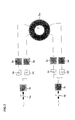
- FIG. 2 shows a circuit arrangement for a drive motor 5a which is formed with four groups of electromagnets.
- This arrangement consists of two rectifier circuits 1a and 1b, which are connected to the feed network via line filters 4a and 4b.
- Two storage circuits 2a, 2b, 2c and 2d and two converter circuits 3a, 3b, 3c and 3d are connected to the rectifier circuits 1a and 1b, through which four groups of electromagnets arranged on the stator of the electric motor 5 are fed.
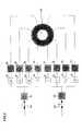
- FIG. 3 shows a circuit arrangement for the control of an electric motor 5b, which has eight groups of electromagnets, each of which is independent of one another via the filter circuits 4c, 4d, the rectifier circuits 1c, 1d, the memory circuits 2e to 21 and the converter circuits 3e to 31 frequency-controlled AC voltages can be supplied.
Landscapes
- Engineering & Computer Science (AREA)
- Power Engineering (AREA)
- Control Of Ac Motors In General (AREA)
- Permanent Magnet Type Synchronous Machine (AREA)
- Electric Propulsion And Braking For Vehicles (AREA)
Applications Claiming Priority (2)
| Application Number | Priority Date | Filing Date | Title |
|---|---|---|---|
| AT3602002 | 2002-03-07 | ||
| AT3602002 | 2002-03-07 |
Publications (2)
| Publication Number | Publication Date |
|---|---|
| EP1343246A2 true EP1343246A2 (fr) | 2003-09-10 |
| EP1343246A3 EP1343246A3 (fr) | 2004-02-04 |
Family
ID=27739932
Family Applications (1)
| Application Number | Title | Priority Date | Filing Date |
|---|---|---|---|
| EP02450280A Withdrawn EP1343246A3 (fr) | 2002-03-07 | 2002-12-12 | Circuit pour l'alimentation d'un moteur électrique |
Country Status (3)
| Country | Link |
|---|---|
| US (1) | US6741062B2 (fr) |
| EP (1) | EP1343246A3 (fr) |
| CA (1) | CA2418929A1 (fr) |
Cited By (2)
| Publication number | Priority date | Publication date | Assignee | Title |
|---|---|---|---|---|
| EP1521356A2 (fr) | 2003-09-30 | 2005-04-06 | Vacon Oyj | Contrôle des convertisseurs ou invertisseurs de fréquence opérés en parallèle |
| WO2014063774A3 (fr) * | 2012-10-22 | 2014-09-18 | Sew-Eurodrive Gmbh & Co. Kg | Système d'entraînement équipé d'un accumulateur d'énergie |
Families Citing this family (1)
| Publication number | Priority date | Publication date | Assignee | Title |
|---|---|---|---|---|
| UA110967C2 (uk) * | 2011-04-04 | 2016-03-10 | Флсмідт А/С | Високопродуктивний млин |
Family Cites Families (12)
| Publication number | Priority date | Publication date | Assignee | Title |
|---|---|---|---|---|
| US3909685A (en) * | 1974-01-14 | 1975-09-30 | Massachusetts Inst Technology | Electrical apparatus |
| US4434389A (en) * | 1980-10-28 | 1984-02-28 | Kollmorgen Technologies Corporation | Motor with redundant windings |
| JPS58177864A (ja) * | 1982-04-07 | 1983-10-18 | 株式会社日立製作所 | 交流エレベ−タ−の制御装置 |
| JPS60207475A (ja) * | 1984-03-30 | 1985-10-19 | Toshiba Corp | エレベ−タ制御装置 |
| IT1263465B (it) * | 1993-02-10 | 1996-08-05 | Sasib Spa | Metodo d'azionamento per macchine automatiche e dispositivo per l'attuazione del detto metodo. |
| US5589743A (en) * | 1995-03-03 | 1996-12-31 | General Electric Company | Integrated cranking inverter and boost converter for a series hybrid drive system |
| US5893432A (en) * | 1996-12-31 | 1999-04-13 | Inventio Ag | Controlled emergency stop apparatus for elevators |
| AT6706U1 (de) * | 1999-10-11 | 2004-02-25 | Innova Patent Gmbh | Elektromotor |
| JP2001187677A (ja) * | 1999-12-28 | 2001-07-10 | Mitsubishi Electric Corp | エレベータの制御装置 |
| JP2001226049A (ja) * | 2000-02-15 | 2001-08-21 | Mitsubishi Electric Corp | エレベータの制御装置 |
| JP4249364B2 (ja) * | 2000-02-28 | 2009-04-02 | 三菱電機株式会社 | エレベータの制御装置 |
| IT1316130B1 (it) * | 2000-05-18 | 2003-03-28 | High Technology Investiments B | Impianto motore con apparecchiatura per il comando di disinserimento efermata regolato e/o modulato di una funivia. |
-
2002
- 2002-12-12 EP EP02450280A patent/EP1343246A3/fr not_active Withdrawn
-
2003
- 2003-02-14 CA CA002418929A patent/CA2418929A1/fr not_active Abandoned
- 2003-02-19 US US10/368,788 patent/US6741062B2/en not_active Expired - Fee Related
Cited By (2)
| Publication number | Priority date | Publication date | Assignee | Title |
|---|---|---|---|---|
| EP1521356A2 (fr) | 2003-09-30 | 2005-04-06 | Vacon Oyj | Contrôle des convertisseurs ou invertisseurs de fréquence opérés en parallèle |
| WO2014063774A3 (fr) * | 2012-10-22 | 2014-09-18 | Sew-Eurodrive Gmbh & Co. Kg | Système d'entraînement équipé d'un accumulateur d'énergie |
Also Published As
| Publication number | Publication date |
|---|---|
| US20030169016A1 (en) | 2003-09-11 |
| CA2418929A1 (fr) | 2003-09-07 |
| EP1343246A3 (fr) | 2004-02-04 |
| US6741062B2 (en) | 2004-05-25 |
Similar Documents
| Publication | Publication Date | Title |
|---|---|---|
| DE2932549C2 (de) | Stromversorgungssystem für Langstator-Linearmotor | |
| EP2109021A1 (fr) | Machine issue de la technique d'automatisation et installation de production | |
| EP2541755A1 (fr) | Dispositif d'entraînement pour un véhicule | |
| EP3467990B1 (fr) | Dispositif de fourniture d'énergie destiné à fournir de l'énergie électrique à au moins un terminal ainsi que procédé de fonctionnement d'un dispositif de fourniture d'énergie | |
| DE102014212934A1 (de) | Vorrichtung und Verfahren zum Ladezustandsausgleich eines Energiespeichersystems | |
| EP3918695A1 (fr) | Entraînement électrique et procédé servant à faire fonctionner l'entraînement électrique | |
| DE102022202154B3 (de) | Traktionsnetz für ein Kraftfahrzeug | |
| DE102014113489A1 (de) | Elektrische Maschine | |
| WO2023006729A1 (fr) | Système d'entraînement électrique pour véhicule et procédé pour faire fonctionner un système d'entraînement électrique correspondant | |
| WO2004068694A1 (fr) | Machine electrique pour la propulsion d'un sous-marin au moyen d'une machine synchrone excitee par des aimants permanents | |
| EP2067227B1 (fr) | Alimentation en énergie motrice pour véhicules ferroviaires | |
| EP3471235B1 (fr) | Dispositif de fourniture d'énergie destiné à fournir de l'énergie électrique à un véhicule automobile ainsi que procédé de fonctionnement d'un dispositif de fourniture d'énergie | |
| WO2003025390A1 (fr) | Installation de parc eolien | |
| EP1343246A2 (fr) | Circuit pour l'alimentation d'un moteur électrique | |
| DE2626372A1 (de) | Vorrichtung zum abtrennen elektrisch leitender bestandteile aus mischungen, insbesondere aus muell | |
| DE102019202374A1 (de) | Antriebssystem, insbesondere für ein Fahrzeug | |
| WO2022022769A1 (fr) | Modularisation de machine électrique et système électronique de puissance ayant le facteur de remplissage le plus élevé, par ex., un facteur de remplissage de fente | |
| DE102004040228B4 (de) | Fahrzeug mit Elektroantrieb | |
| EP1495525A2 (fr) | Procede de transmission inductive d'energie electrique | |
| DE102014212930B3 (de) | Vorrichtung zum Bereitstellen einer elektrischen Spannung sowie Antriebsanordnung und Verfahren | |
| EP3373431A1 (fr) | Convertisseur d'énergie réglable destiné à convertir l'énergie électrique en énergie thermique | |
| EP0613236B1 (fr) | Dispositif de mise en service d'un compresseur pour climatiseurs d'armoires électriques | |
| EP1927686B1 (fr) | Métiers à tisser dotés d'un actionnement électrique | |
| WO2012127011A2 (fr) | Procédé de commande ou de régulation d'un moteur électrique rotatif et moteur électrique rotatif | |
| WO2012136396A1 (fr) | Piézo-transformateur, procédé de fabrication d'un piézo-transformateur et onduleur équipé d'un piézo-transformateur |
Legal Events
| Date | Code | Title | Description |
|---|---|---|---|
| PUAI | Public reference made under article 153(3) epc to a published international application that has entered the european phase |
Free format text: ORIGINAL CODE: 0009012 |
|
| AK | Designated contracting states |
Kind code of ref document: A2 Designated state(s): AT BE BG CH CY CZ DE DK EE ES FI FR GB GR IE IT LI LU MC NL PT SE SI SK TR |
|
| AX | Request for extension of the european patent |
Extension state: AL LT LV MK RO |
|
| PUAL | Search report despatched |
Free format text: ORIGINAL CODE: 0009013 |
|
| AK | Designated contracting states |
Kind code of ref document: A3 Designated state(s): AT BE BG CH CY CZ DE DK EE ES FI FR GB GR IE IT LI LU MC NL PT SE SI SK TR |
|
| AX | Request for extension of the european patent |
Extension state: AL LT LV MK RO |
|
| 17P | Request for examination filed |
Effective date: 20040302 |
|
| 17Q | First examination report despatched |
Effective date: 20040519 |
|
| AKX | Designation fees paid |
Designated state(s): AT BE BG CH CY CZ DE DK EE ES FI FR GB GR IE IT LI LU MC NL PT SE SI SK TR |
|
| STAA | Information on the status of an ep patent application or granted ep patent |
Free format text: STATUS: THE APPLICATION IS DEEMED TO BE WITHDRAWN |
|
| 18D | Application deemed to be withdrawn |
Effective date: 20050708 |