EP1343274A2 - Kommunikationssystem, Kommunikationsverfahren, Netzwerksverwalter und Übertragungsvorrichtung - Google Patents
Kommunikationssystem, Kommunikationsverfahren, Netzwerksverwalter und Übertragungsvorrichtung Download PDFInfo
- Publication number
- EP1343274A2 EP1343274A2 EP20030004337 EP03004337A EP1343274A2 EP 1343274 A2 EP1343274 A2 EP 1343274A2 EP 20030004337 EP20030004337 EP 20030004337 EP 03004337 A EP03004337 A EP 03004337A EP 1343274 A2 EP1343274 A2 EP 1343274A2
- Authority
- EP
- European Patent Office
- Prior art keywords
- terminal
- transfer device
- data
- routing
- information
- Prior art date
- Legal status (The legal status is an assumption and is not a legal conclusion. Google has not performed a legal analysis and makes no representation as to the accuracy of the status listed.)
- Granted
Links
Images




Classifications
-
- H—ELECTRICITY
- H04—ELECTRIC COMMUNICATION TECHNIQUE
- H04L—TRANSMISSION OF DIGITAL INFORMATION, e.g. TELEGRAPHIC COMMUNICATION
- H04L12/00—Data switching networks
- H04L12/28—Data switching networks characterised by path configuration, e.g. LAN [Local Area Networks] or WAN [Wide Area Networks]
-
- H—ELECTRICITY
- H04—ELECTRIC COMMUNICATION TECHNIQUE
- H04W—WIRELESS COMMUNICATION NETWORKS
- H04W8/00—Network data management
- H04W8/02—Processing of mobility data, e.g. registration information at HLR [Home Location Register] or VLR [Visitor Location Register]; Transfer of mobility data, e.g. between HLR, VLR or external networks
- H04W8/08—Mobility data transfer
- H04W8/16—Mobility data transfer selectively restricting mobility data tracking
-
- H—ELECTRICITY
- H04—ELECTRIC COMMUNICATION TECHNIQUE
- H04L—TRANSMISSION OF DIGITAL INFORMATION, e.g. TELEGRAPHIC COMMUNICATION
- H04L41/00—Arrangements for maintenance, administration or management of data switching networks, e.g. of packet switching networks
-
- H—ELECTRICITY
- H04—ELECTRIC COMMUNICATION TECHNIQUE
- H04L—TRANSMISSION OF DIGITAL INFORMATION, e.g. TELEGRAPHIC COMMUNICATION
- H04L45/00—Routing or path finding of packets in data switching networks
-
- H—ELECTRICITY
- H04—ELECTRIC COMMUNICATION TECHNIQUE
- H04L—TRANSMISSION OF DIGITAL INFORMATION, e.g. TELEGRAPHIC COMMUNICATION
- H04L45/00—Routing or path finding of packets in data switching networks
- H04L45/42—Centralised routing
-
- H—ELECTRICITY
- H04—ELECTRIC COMMUNICATION TECHNIQUE
- H04L—TRANSMISSION OF DIGITAL INFORMATION, e.g. TELEGRAPHIC COMMUNICATION
- H04L61/00—Network arrangements, protocols or services for addressing or naming
-
- H—ELECTRICITY
- H04—ELECTRIC COMMUNICATION TECHNIQUE
- H04L—TRANSMISSION OF DIGITAL INFORMATION, e.g. TELEGRAPHIC COMMUNICATION
- H04L61/00—Network arrangements, protocols or services for addressing or naming
- H04L61/50—Address allocation
-
- H—ELECTRICITY
- H04—ELECTRIC COMMUNICATION TECHNIQUE
- H04W—WIRELESS COMMUNICATION NETWORKS
- H04W8/00—Network data management
- H04W8/26—Network addressing or numbering for mobility support
-
- H—ELECTRICITY
- H04—ELECTRIC COMMUNICATION TECHNIQUE
- H04W—WIRELESS COMMUNICATION NETWORKS
- H04W80/00—Wireless network protocols or protocol adaptations to wireless operation
- H04W80/04—Network layer protocols, e.g. mobile IP [Internet Protocol]
Definitions
- the present invention relates to a communications system and a communications method for transmitting data including, as a destination address, a second terminal ID (information identifying the second terminal), from a first terminal to the second terminal via a plurality of transfer devices, and a transfer device and a network manager suitable for use therein.
- a terminal moving within a communications network uses address information assigned by an access network with which the terminal has newly established connection at a new location, for communications.
- a given address information piece is assigned to the terminal from among address information pieces assigned to an access network to which the terminal is physically connected.
- the conventional communications system has a problem in that when the terminal conducts communications using the assigned address information, the party on the other end of the connection can detect from the address information the access network to which the above terminal is physically connected. That is, in such a case, the location information of the user can be problematically leaked to the party on the other end.
- Mobile IP As an art designed to provide packet transmitting and receiving functions to a terminal moving within a communications network under the same setting environment, "Mobile IP" is known.
- the terminal In order to prevent the leakage of the location information of the user, the terminal always transmits to the party on the other end, data with a "home address" assigned by a “home agent” of a “home network” set as the source address.
- the party on the other end always transmits data provided with the "home address” to the terminal, assuming that the terminal is located in the "home network.”
- the data transmitted from the party on the other end is always transferred to the "home network (home agent)" of the terminal and then transferred from the "home network” to a network to which the terminal is connected at that time.
- the conventional communications system using "Mobile IP” has another problem in view of a data transfer path in which data transferred must pass through a relay point (home agent) constituting a triangular path.
- the conventional communications system using "Mobile IP” has yet another problem in that the terminal needs to perform highly functional processing.
- the terminal needs, for example, to hold both the address information assigned by an access network to which the terminal is connected, and the home address of the terminal, and to perform such processing as releasing the encapsulation of packets received.
- the conventional communications system using "Mobile IP” has still another problem in that it is required to transmit and receive packets in a format which includes an information element constituting an overhead, even in a radio section between the terminal and an access point in the access network.
- the conventional communications system using "Mobile IP” has still another problem in that it is based on "end-to-end data transfer" , a basic principle of the internet protocol, and the terminal needs to specify, as transfer information, both a terminal ID and routing information (that is, address information assigned by an access network and a terminal home address) for data transfer.
- the conventional communications system using "Mobile IP” has still another problem in that path-to-path processing, routing processing, or the like, results in a transmission mode including redundant path information.
- the conventional communications system using "Mobile IP” has still another problem in that since bandwidth control is performed by encapsulation using MPLS or the like, the party on the other end can detect the location information of the terminal from address information assigned by an access network.
- the present invention has been made in view of the above and has an object of providing a communications system and a communications method which allow data transfer not using a terminal ID assigned by an access network but using routing information distinct from the terminal ID, and a transfer device and a network manager suitable for use therein.
- a communications system for transmitting data including, as a destination address, a second terminal ID (information identifying a second terminal), from a first terminal to the second terminal via a plurality of transfer devices, the system comprising: a first transfer device connected to the first terminal, the first transfer device comprising: a first memory configured to store the second terminal ID and routing information for routing the data to a second transfer device connected to the second terminal, associating them with one another; and a routing processor configured to add to the data the routing information associated with the second terminal ID included in the data received from the first terminal, and to transfer the data to the second transfer device.
- the communications system preferably further comprises a network manager, the network manager comprising: a second memory configured to store the second terminal ID and the routing information for routing the data to the second transfer device, associating them with one another; and an instruction information transmitter configured to transmit instruction information including the routing information for routing the data to the second transfer device associated with the second terminal ID, in response to a transfer request including the second terminal ID transmitted from the first transfer device; wherein, the first transfer device comprises a transfer request transmitter configured to transmit the transfer request to the network manager upon receiving a transmission request for the data from the first terminal; and the first memory stores the second terminal ID and the routing information for routing the data to the second transfer device, associating them with one another, according to the instruction information from the network manager.
- a network manager comprising: a second memory configured to store the second terminal ID and the routing information for routing the data to the second transfer device, associating them with one another; and an instruction information transmitter configured to transmit instruction information including the routing information for routing the data to the second transfer device associated with the second terminal ID, in response to
- the instruction information transmitter preferably transmits the instruction information to the second transfer device.
- the first memory preferably stores the second terminal ID and the routing information for routing the data to the second transfer device, associating them with one another, according to the instruction information received via the second transfer device.
- the data transmission request preferably includes control information on the transmission of the data from the first terminal to the second terminal.
- the first memory preferably stores the second terminal ID, the routing information for routing the data to the second transfer device and the control information, associating them with one another.
- the routing processor preferably transfers the data to the second transfer device, based on the control information.
- the first memory alternatively stores a first terminal ID (information identifying the first terminal), the second terminal ID, the routing information for routing the data to the second transfer device and a communication ID element, associating them with one another.
- the routing processor preferably adds to the data the routing information associated with the communication ID element included in the data received from the first terminal, and transfers the data to the second transfer device.
- the network manager alternatively comprises a third memory configured to store the first terminal ID, the second terminal ID, the routing information for routing the data to the second transfer device and the communication ID element, associating them with one another; and an instruction information transmitter configured to transmit instruction information including the routing information and the communication ID element associated with the first terminal ID and the second terminal ID, in response to a transfer request including the first terminal ID and the second terminal ID transmitted from the first transfer device.
- the first transfer device preferably comprises a transfer request transmitter configured to transmit the transfer request to the network manager upon receiving a transmission request for the data from the first terminal.
- the first memory preferably stores the first terminal ID, the second terminal ID, the routing information for routing the data to the second transfer device and the communication ID element, associating them with one another, according to the instruction information from the network manager.
- a communications method of transmitting data including, as a destination address, a second terminal ID, from a first terminal to the second terminal via a plurality of transfer devices, the method comprising the step of: A) adding to the data, at a first transfer device which is connected to the first terminal and stores the second terminal ID and routing information for routing the data to a second transfer device to which the second terminal is connected, associating them with one another, the routing information associated with the second terminal included in the data, and transferring the data to the second transfer device.
- the communications method preferably further comprises the steps of: B) transmitting, at the first transfer device, a transfer request including the second terminal ID to a network manager upon receiving a transmission request for the data from the first terminal; C) transmitting, at the network manager, instruction information including the routing information associated with the second terminal ID, in response to the transfer request transmitted from the first transfer device; and D) storing, at the first transfer device, the second terminal ID and the routing information for routing the data to the second transfer device, associating them with one another, according to the instruction information from the network manager.
- step C) the network manager preferably transmits the instruction information to the second transfer device; and in step D) , the first transfer device preferably stores the second terminal ID and the routing information for routing the data to the second transfer device, associating them with one another, according to the instruction information received via the second transfer device.
- the data transmission request preferably includes control information on the transmission of the data from the first terminal to the second terminal; the first transfer device preferably stores the second terminal ID, the routing information for routing the data to the second transfer device and the control information, associating them with one another; and in step A), the first transfer device preferably transfers the data to the second transfer device based on the control information.
- the first transfer device alternatively stores the first terminal ID, the second terminal ID, the routing information for routing the data to the second transfer device and a communication ID element, associating them with one another; and in step A), the first transfer device adds to the data the routing information associated with the communication ID element included in the data received from the first terminal, and transfers the data to the second transfer device.
- the communications method preferably further comprises the steps of: E) transmitting, at the first transfer device, a transfer request including the first terminal ID and the second terminal ID to a network manager upon receiving a transmission request for the data from the first terminal, the network manager storing the first terminal ID, the second terminal ID, the routing information for routing the data to the second transfer device and the communication ID information element, associating them with one another; F) transmitting, at the network manager, instruction information including the routing information and the communication ID element associated with the first terminal ID and the second terminal ID, in response to the transfer request transmitted from the first transfer device; and G) storing, at the first transfer device, the first terminal ID, the second terminal ID, the routing information for routing the data to the second transfer device and the communication ID element, associating them with one another, according to the instruction information from the network manager.
- a first transfer device connected to a first terminal for transmitting data including, as a destination address, a second terminal ID, from the first terminal to the second terminal, the first transfer device comprising: a first memory configured to store the second terminal ID and routing information for routing the data to a second transfer device to which the second terminal is connected, associating them with one another; and a routing processor configured to add to the data the routing information associated with the second terminal ID included in the data, and to transfer the data to the second transfer device.
- the first transfer device preferably further comprises: a transfer request transmitter configured to transmit a transfer request including the second terminal ID to a network manager upon receiving a transmission request for the data from the first terminal; wherein, the first memory stores the second terminal ID and the routing information for routing the data to the second transfer device, associating them with one another, upon receiving instruction information including the routing information associated with the second terminal ID from the network manager.
- the first memory alternatively stores a first terminal ID, the second terminal ID, the routing information for routing the data to the second transfer device and a communication ID element, associating them with one another; and the routing processor adds to the data the routing information associated with the communication ID element included in the data received from the first terminal, and transfers the data to the second transfer device.
- the first transfer device further comprises a transfer request transmitter configured to transmit a transfer request including the first terminal ID and the second terminal ID to a network manager upon receiving a transmission request for the data from the first terminal.
- the first memory stores the first terminal ID and the second terminal ID, the routing information for routing the data to the second transfer device and the communication ID element, associating them with one another, according to instruction information from the network manager.
- a network manager for managing a communications system for transmitting data including, as a destination address, a second terminal ID, from a first terminal to the second terminal via a plurality of transfer devices, the network manager comprising: a second memory storing the second terminal ID and routing information for routing the data to a second transfer device to which the second terminal is connected, associating them with one another; and an instruction information transmitter configured to transmit instruction information including the routing information associated with the second terminal ID, in response to a transfer request including the second terminal ID transmitted from a first transfer device to which the first terminal is connected.
- a network manager for managing a communications system for transmitting data including a second terminal ID as a destination address and including a first terminal ID as a source address, from the first terminal to the second terminal via a plurality of transfer devices
- the network manager comprising: a third memory configured to store the first terminal ID, the second terminal ID, routing information for routing the data to a second transfer device to which the second terminal is connected and a communication ID element, associating them with one another; and an instruction information transmitter configured to transmit instruction information including the routing information for routing the data to the second transfer device to which the second terminal is connected and the communication ID element associated with the first terminal ID and the second terminal ID, in response to a transfer request including the first terminal ID and the second terminal ID transmitted from a first transfer device.
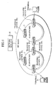
- FIG. 1 illustrates the entire configuration of the communications system of this embodiment.
- the communications system of this embodiment transmits data including information identifying a second terminal 51 (hereinafter referred to as an ID-terminal 51) as the destination address and including information identifying a first terminal 52 (hereinafter referred to as an ID-terminal 52) as the source address, from the first terminal 52 to the second terminal 51 via a plurality of transfer devices 30 1 , 30 3 , 20 3 and 20 1 , as shown in FIG. 1.
- the first terminal 51 and the second terminal 52 can move in subnetworks (access networks) 2 and 3 constituting a network 1, being connected to the transfer devices (access points) 30 1 and 20 1 , for example, in the subnetworks 2 and 3 in a wireless or wired system.
- This embodiment will be described with the first terminal 51 and the second terminal 52 wirelessly connected to the transfer devices (access points) 30 1 and 20 1 , for example, in the subnetworks 2 and 3.
- the "ID-terminal 51" and “ID-terminal 52" may be any address information such as IP addresses assigned to the first terminal 52 and the second terminal 51, respectively.
- the communications system of this embodiment includes a network manager 10 and a plurality of transfer devices 20 1 to 20 3 and 30 1 to 30 3 , as shown in FIG. 1.
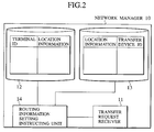
- the network manager 10 manages the communications system (network 1) of this embodiment. More specifically, the network manager 10 includes, as shown in FIG. 2, a transfer request receiver 11, a terminal ID-location information associating unit 12, a location information-transfer device ID associating unit 13, and a routing information setting instructing unit 14.
- the transfer request receiver 11 is connected to the routing information setting instructing unit 14.
- the receiver 11 receives a "transfer request" including the "the second terminal ID (destination terminal ID, ID-terminal 51)" transmitted from the first transfer device 30 1 to which the first terminal 52 is connected, and transmits the received transfer request to the routing information setting instructing unit 14.
- the transfer request may include control information for controlling a communication bandwidth or the like (e.g., 64 Kbps).
- the terminal ID-location information associating unit 12 is connected to the routing information setting instructing unit 14.
- the unit 12 stores "terminal IDs" of terminals located in the network 1 and associated "location information" of the terminals.
- the location information-transfer device ID associating unit 13 is connected to the routing information setting instructing unit 14.
- the unit 13 stores "transfer device IDs" and associated "location information" of the terminals which can be connected to the transfer devices.
- the terminal ID-location information associating unit 12 and the location information-transfer device ID associating unit 13 may be united to associate the "terminal IDs" with the "transfer device IDs" to which the terminals are connected.
- the routing information setting instructing unit 14 is connected to the transfer request receiver 11, the terminal ID-location information associating unit 12 and the location information-transfer device ID associating unit 13.
- the routing information setting instructing unit 14 constitutes an instruction information transmitter for transmitting, in response to a transfer request transmitted through the transfer request receiver 11, a "routing information setting instruction (instruction information)" including the "destination transfer device ID (routing information for routing the data to the second transfer device 20 1 )" associated with the "second terminal ID (ID-terminal 51).”
- the "routing information setting instruction can include a terminal ID identifying a terminal connected to the destination transfer device, instead of the destination transfer device ID.
- the "routing information setting instruction (instruction information)" may include control information included in the transfer request.
- the routing information setting instructing unit 14 searches the terminal ID-location information associating unit 12 and the location information-transfer device ID associating unit 13, with the "second terminal ID (ID-terminal 51)" included in the transfer request as a keyword, thereby obtaining the "information identifying the second transfer device 20 1 (routing information for routing the data to the second transfer device 20 1 )" associated with the "second terminal ID (ID-terminal 51),” and transmits to each of the plurality of transfer devices 20 3 , 30 1 and 30 3 a "routing information setting instruction (instruction information)" including the "information identifying the second transfer device 20 1 (RA-20 1 )” and "transfer information (RA-30 3 )."
- the routing information setting instructing unit 14 may transmit the "routing information setting instruction (instruction information)" to all transfer devices located in the network 1.
- the routing information setting instructing unit 14 constitutes a second memory which stores the "second terminal ID (ID-terminal 51)" and the "second transfer device ID, that is, the routing information for routing the data to the second transfer device (e.g., RA-20 1 for the transfer device 30 1 )." associating them with one another.
- the routing information can be a terminal ID identifying a terminal connected to the transfer device 30 1 , instead of RA-20 1 .
- the memory contents of the second memory may be set by a network administrator or may be dynamically obtained by the network manager 10 from a transfer device in a specified area upon the transfer request.
- the plurality of transfer devices 20 and 30 cooperatively transfer from the first terminal 52 to the second terminal 51 the data including the "second terminal ID (ID-terminal 51)" as the destination address and the "first terminal ID (ID-terminal 52)" as the source address.
- the transfer devices 20 and 30 each include, as shown in FIG. 3, a receiver 21, a transfer request transmitter 22, a routing information setting instruction receiver 23, a terminal ID-routing information-control information associating unit 24, a routing processor 25, and a transmitter 26. Description will be made below with the first transfer device 30 1 to which the first terminal 52 is connected.
- the receiver 21 is connected to the transfer request transmitter 22, terminal ID-routing information-control information associating unit 24 and routing processor 25.
- the receiver 21 receives data transmitted from the first terminal 52 and transfers the received data to the routing processor 25.
- the receiver 21 searches, in response to the data transmission request, the terminal ID-routing information-control information associating unit 24 for a record including the "second terminal ID" included in the data (or data transmission request).
- the receiver 21 transfers to the routing processor 25 the data including the data transmission request or data transmitted subsequently to the data transmission request.
- the receiver 21 transfers the data transmission request including the "second terminal ID" to the transfer request transmitter 22.
- the data transmission request includes, for example, the "first terminal ID (ID-terminal 52)" as the source address, the "second terminal ID (ID-terminal 51)" as the destination address, and control information for controlling the communication bandwidth or the like (e.g., 64 Kbps).
- the first terminal 52 transmits data transmission request including the control information to the transfer device 30 1 .
- the transfer request transmitter 22 is connected to the receiver 21. In response to the "data transmission request" transmitted through the receiver 21, the transmitter 22 transmits a transfer request including the "second terminal ID (ID-terminal 51)" and the "control information (e.g., 64 Kbps)" to the network manager 10.
- the routing information setting instruction receiver 23 is connected to the terminal ID-routing information-control information associating unit 24.
- the receiver 23 receives a "routing information setting instruction (instruction information)" transmitted from the network manager 10 and updates the memory contents of the terminal ID-routing information-control information associating unit 24 according to the received "routing information setting instruction (instruction information )."
- the terminal ID-routing information-control information associating unit 24 is connected to the routing information setting instruction receiver 23 and the routing processor 25.
- the unit 24 constitutes a first memory storing "IDs of destination terminals (destination terminal IDs)," “IDs of transfer devices (destination transfer device IDs) to which the destination terminals are connected,” “transfer information” for the transfer of the received data, and the "control information” for the transmission of data to the transfer devices, associating them with one another.
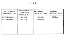
- FIG. 4 illustrates an example of the memory contents of the terminal ID-routing information-control information associating unit 24 of the first transfer device 30 1 .
- the second record shows that the first terminal 52 is wirelessly connected to the first transfer device 30 1 .
- the routing processor 25 is connected to the receiver 21, the terminal ID-routing information-control information associating unit 24 and the transmitter 26.
- the routing processor 25 adds to the data the "routing information for routing the data to the destination transfer device 20 1 (ID RA-20 1 of the second transfer device 20 1 )'' associated with the "second terminal ID (ID-terminal 51)" included in the data transmitted via the receiver 21 from the first terminal 52, and transfers the data via the transmitter 26 to the transfer device 30 3 based on the "control information (e.g., 64 Kbps)" associated with the "second terminal ID (ID-terminal 51)."
- control information e.g., 64 Kbps
- the transmitter 26 is connected to the routing processor 25.
- the transmitter 26 transfers the data transmitted from the routing processor 25 to the second transfer device 20 1 , that is, to the transfer device 30 3 .
- FIG. 5 is a sequence diagram illustrating the operation of the communications system of this embodiment.
- data including a data transmission request
- second terminal ID destination ID, ID-terminal 51
- first terminal ID source terminal ID, ID-terminal 52
- user information such as a payload
- the receiver 21 of the first transfer device 30 1 Upon receiving the data transmission request, the receiver 21 of the first transfer device 30 1 searches the terminal ID-routing information-control information associating unit 24 for a record including the "second terminal ID (ID-terminal 51)" as the "destination terminal ID.”
- the routing processor 25 adds, in step 405, to the data the "destination transfer device ID, that is, the routing information for routing the data to the second transfer device 20 1 (ID RA-20 1 of the second transfer device 20 1 )" associated with the “second terminal ID (ID-terminal 51),” and transfers the data to the transfer device 30 3 specified in the “transfer information” associated with the "second terminal ID (ID-terminal 51),” based on the "control information” associated with the "second terminal ID (ID-terminal 51)” (see FIG. 6B).
- step 403 upon the transfer request received via the transfer request receiver 11, the routing information setting instructing unit 14 of the network manager 10 searches the terminal ID-location information associating unit 12 and the location information-transfer device ID associating unit 13, with the "second terminal ID (ID-terminal 51)" included in the transfer request as a keyword.
- the routing information setting instruction receiver 23 of each of the plurality of transfer devices 20 1 , 20 3 , 30 1 and 30 3 updates the memory contents of the terminal ID-routing information-control information associating unit 24 according to the "routing information setting instruction (instruction information)" received from the network manager 10.
- the routing information setting instruction receiver 23 of the first transfer device 30 1 for example, updates the terminal ID-routing information-control information associating unit 24 according to the "routing information setting instruction (instruction information)" as shown in FIG. 4.
- the data transmitted includes, as shown in FIG. 6B, the "routing information for routing the data to the second transfer device 20 1 (RA-20 1 )," the destination address "second terminal ID (destination terminal ID, ID-terminal 51),” the source address "first terminal ID (source terminal ID, ID-terminal 52)” and the "user information (payload).”
- the transfer device 30 3 transfers, in the same manner as the first transfer device 30 1 , the data received from the first transfer device 30 1 to the transfer device 20 3 connected to the subnetwork 2.
- the data transmitted includes, as shown in FIG. 6B, the "routing information for routing the data to the second transfer device 20 1 (ID RA-20 1 )," the destination address "second terminal ID (destination terminal ID, ID-terminal 51),” the source address "first terminal ID (source terminal ID, ID-terminal 52)” and the "user information.”
- the transfer device 20 3 transfers, in the same manner as the first transfer device 30 1 , the data received from the transfer device 30 3 to the second transfer device 20 1 .
- the data transferred includes, as shown in FIG. 6B, the "routing information for routing the data to the second transfer device 20 1 (RA-20 1 )," the destination address "second terminal ID (destination terminal ID, ID-terminal 51),” the source address "first terminal ID (source terminal ID, ID-terminal 52)" and the "user information.”
- the second transfer device 20 1 deletes the "routing information for routing the data to the second transfer device 20 1 (RA-20 1 )'' from the data received from the transfer device 20 3 and transmits the data to the second terminal 51.
- the data transferred includes, as shown in FIG. 6A, the destination address "second terminal ID (destination terminal ID, ID-terminal 51)," the source address "first terminal ID (source terminal ID, ID-terminal 52)" and the "user information.”
- step 410 the receiver 21 of the second transfer device 20 1 searches the terminal ID-routing information-control information associating unit 24 for a record including the "first terminal ID (destination terminal ID, ID-terminal 52)" as the "destination terminal ID,” according to the data including the data transmission request.
- the routing processor 25 of the second transfer device 20 1 adds, in step 410, to the data "routing information for routing the data to the first transfer device (RA-30 1 )" associated with the "first terminal ID (destination terminal ID, ID-terminal 52),” and transfers the data via the transmitter 26 to the transfer device 203 specified in the "transfer information" associated with the "first terminal ID (destination terminal ID, ID-terminal 52),” based on the "control information.”
- the data transmitted includes, as shown in FIG. 6B, the "routing information for routing the data to the first transfer device 30 1 (ID RA-30 1 )," the destination address "first terminal ID (destination terminal ID, ID-terminal 52),” the source address "second terminal ID (source terminal ID, ID-terminal 51)" and the "user information.”
- the transfer device 20 3 transfers, in the same manner as the second transfer device 20 1 , the data received from the second transfer device 20 1 to the transfer device 30 3 connected to the subnetwork 3.
- the data transferred includes, as shown in FIG. 6B, the "routing information for routing the data to the first transfer device 30 1 (ID RA-30 1 )," the destination address "first terminal ID (destination terminal ID, ID-terminal 52),” the source address "second terminal ID (source terminal ID, ID-terminal 51)" and the "user information.”
- the transfer device 30 3 transfers, in the same manner as the second transfer device 20 1 , the data received from the transfer device 20 3 to the first transfer device 30 1 .
- the data transferred includes, as shown in FIG. 6B, the "routing information for routing the data to the first transfer device 30 1 (ID RA-30 1 )," the destination address "first terminal ID (destination terminal ID, ID-terminal 52),” the source address "second terminal ID (source terminal ID, ID-terminal 51)" and the "user information.”
- the first transfer device 30 1 deletes the "routing information for routing the data to the first transfer device 30 1 (RA-30 1 )" from the data received from the transfer device 30 3 and transmits the data to the first terminal 52.
- the data transferred includes, as shown in FIG. 6A, the destination address "first terminal ID (destination terminal ID, ID-terminal 52),” the source address "second terminal ID (source terminal ID, ID-terminal 51)" and the "user information.”
- the terminal ID-routing information-control information associating unit 24 of the first transfer device 30 1 stores the "the second terminal (destination terminal) ID (ID-terminal 51)" and the "routing information for routing the data to the second transfer device 20 1 (RA-20 1 )," associating them with one another, and the routing processor 25 adds to the data the "routing information for routing the data to the second transfer device 20 1 (RA-20 1 ) associated with the "second terminal ID (ID-terminal 51)” and transfers the data from the first terminal 52 to the second terminal 51.
- the first terminal (source terminal) 52 only needs to transmit data including the "second terminal ID(destination terminal) (ID-terminal 51)" as the destination address. This eliminates the need for complicated settings at the first terminal 52.
- the communications system of this embodiment further eliminates the need for holding, at the first terminal 52, both address information assigned by the access network (subnetwork 3) and the home address of the first terminal 52, and performing the release of encapsulation or the like of packets or the like received.
- the first terminal 52 does not need to transmit the "routing information for routing the data to the second transfer device (RA-20 1 )" to the access point in the access network (first transfer device 30 1 ).
- the configuration of a communications system according to a second embodiment of the present invention will be described mainly on difference from the communications system according to the first embodiment.
- the entire configuration of the communications system in the second embodiment of this invention is identical to that of the communications system of the first embodiment.
- a network manager 10 includes, as shown in FIG. 7A, instead of the terminal ID-location information associating unit 12 and the location information-transfer device ID associating unit 13 in the first embodiment, a third memory storing a "communication ID element," a "source terminal ID (first terminal ID) ,” a “destination terminal ID (second terminal ID)” and a “destination transfer device ID (routing information for routing the data to a second transfer device),” associating them with one another.
- a routing information setting instructing unit 14 of the network manager 10 constitutes an instruction information transmitter for transmitting, upon a transfer request including the "first and second terminal IDs" transmitted from a first transfer device 30 1 , a "routing information setting instruction (instruction information)" including the “routing information for routing the data to the second transfer device (destination transfer device ID)" and the "communication ID element” associated with the "first and second terminal IDs.”
- the receiver 21 transmits a "transmission setting response" including the "communication ID element” associated with the record, to the first terminal 52.
- the receiver 21 transfers the "data transmission request" to a transfer request transmitter 22.
- the receiver 21 When receiving data including the "communication ID element" from the first terminal 52, the receiver 21 transfers the data to a routing processor 25.
- the transfer request transmitter 22 transmits, upon the "data transmission request” received through the receiver 21, a "transfer request” including the "first terminal ID,” the "second terminal ID” and "the control information" to the network manager 10.
- the receiver 21 and the transfer request transmitter 22 constitute a transfer request transmitter for transmitting a "transfer request" to the network manager 10 when receiving a "data transmission request" from the first terminal 52.
- a routing information setting instruction receiver 23 updates the memory contents of the terminal ID-routing information-control information associating unit 24, according to a "routing information setting instruction (instructing information)" received from the network manager 10.
- the terminal ID-routing information-control information associating unit 24 constitutes a first memory storing, as shown in FIG. 7B, "communication ID elements,” “source terminal IDs (first terminal IDs),” “destination terminal IDs (second terminal IDs),” “destination transfer device IDs (routing information for routing the data to the second transfer devices),” “transfer information” and “control information,” associating them with one another.
- FIG. 7B illustrates an example of the memory contents of the terminal ID-routing information-control information associating unit 24.
- the routing processor 25 adds to the data the "destination transfer device ID (routing information for routing the data to the second transfer device” associated with the “communication ID element” included in the data received through the receiver 21, and transfers the data to the transfer device specified in the "transfer information" associated with the "communication ID element” based on the "control information.”
- FIG. 8 is a sequence diagram illustrating the operation of the communications system of this embodiment.
- a data format for the transmission is shown in FIG. 9A.
- the receiver 21 of the first transfer device 30 1 searches, upon the "data transmission request," the terminal ID-routing information-control information associating unit 24 for a record including the "second terminal ID (destination terminal ID, ID-terminal 51)" and the “first terminal ID (source terminal ID, ID-terminal 52)."
- the receiver 21 of the first transfer device 30 1 transmits, in step 705, in response to the "data transmission request," a "transmission setting response” including the "communication ID element” associated with the "second terminal ID (destination terminal ID, ID-terminal 51)" and the “first terminal ID (source terminal ID, ID-terminal 52)", to the first terminal 52.
- step 703 upon the transfer request received via the transfer request receiver 11, the routing information setting instructing unit 14 of the network manager 10 searches the third memory, with the "second terminal ID (ID-terminal 51)" and the “first terminal ID (ID-terminal 52)" included in the transfer request as keywords.
- the routing information setting instructing unit 14 obtains the "communication ID element,” the "destination transfer device ID” and the “transfer information” associated with the “second terminal ID (ID-terminal 51)" and the “first terminal ID (ID-terminal 52),” and transmits to a plurality of transfer devices 20 1 , 20 3 , 30 1 and 30 3 , a "routing information setting instruction (instruction information)" including the "communication ID element (71),” the "destination transfer device ID” and the "transfer information.”
- the routing information setting instruction receiver 23 of each of the plurality of transfer devices 20 1 , 20 3 , 30 1 and 30 3 updates the memory contents of the terminal ID-routing information-control information associating unit 24 according to the "routing information setting instruction (instruction information)" received from the network manager 10.
- the routing information setting instruction receiver 23 of the first transfer device 30 1 for example, updates the terminal ID-routing information-control information associating unit 24 according to the "routing information setting instruction (instruction information)" as shown in FIG. 7B.
- step 705 the receiver 21 of the first transfer device 30 1 transmits to the first terminal 52 a "transfer setting response" including the "communication ID element (71)" associated with the “second terminal ID (destination terminal ID, ID-terminal 51)" and the “first terminal ID (source terminal ID, ID-terminal 52)."
- step 706 the first terminal 52 transmits data including the "communication ID element (71)."
- the data transmitted includes, as shown in FIG. 9B, the "communication ID element (71)" and "user information.”
- the routing processor 25 of the first transfer device 30 1 adds to the data the "destination transfer device ID (routing information for routing the data to the second transfer device, RA-20 1 )" associated with the "communication ID element (71)" included in the data transmitted via the receiver 21 from the first terminal 52, and transfers the data via the transmitter 26 to the transfer device 30 3 specified in the "transfer information" associated with the "communication ID element (71).”
- the data transmitted includes, as shown in FIG. 9C, the "destination transfer device ID (routing information for routing the data to the second transfer device 20 1 , RA-20 1 ),” the communication ID element (71)" and the “user information.”
- the transfer device 30 3 transfers, in the same manner as the first transfer device 30 1 , the data received from the first transfer device 30 1 to the transfer device 20 3 connected to a subnetwork 2.
- the data transferred includes, as shown in FIG. 9C, the "destination transfer device ID (routing information RA-20 1 of the second transfer device 20 1 )," the communication ID element (71)" and the “user information.”
- the transfer device 20 3 transfers, in the same manner as the first transfer device 30 3 , the data received from the transfer device 30 3 to the second transfer device 20 1 .
- the data transferred includes, as shown in FIG. 9C, the "destination transfer device ID (routing information RA-20 1 of the second transfer device 20 1 ),'' the communication ID element (71)" and the "user information.”
- the second transfer device 20 1 deletes the "destination transfer device ID (routing information RA-20 1 of the second transfer device)" from the data received from the transfer device 20 3 and transmits the data to the second terminal 51.
- the data transmitted includes, as shown in FIG. 9B, the "communication ID element (71)" and the "user information.”
- step 711 the second terminal 51 transmits data including the "communication ID element (71)."
- the data transmitted includes, as shown in FIG. 9B, the "communication ID element (71)” and the "user information.”
- the data is transmitted to the first terminal 51 in the same manner as in steps 707 to 710.
- the routing processor 25 adds to the data the routing information associated with the communication ID element included in the data received from the first terminal 52 and transfers the data to the second transfer device 20 1 , the first terminal ID and the second terminal ID are not included in data transferred in the communications system, increasing the confidentiality of communications.
- a communications system according to a third embodiment of the present invention will be described mainly on difference from the communications system of the first embodiment.
- the communications system according to this embodiment is different from the communication system of the first embodiment in that a routing information setting instructing unit 14 of a network manager 10 transmits a "routing information setting instruction (instruction information)" to a second transfer device 20 1 instead of transmitting to a plurality of transfer devices 20 1 , 20 3 , 30 1 and 30 3 , and the second transfer device 20 1 transmits the "routing information setting instruction (instruction information)" to the plurality of transfer devices 20 3 , 30 1 and 30 3 .
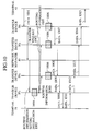
- the operation of the communications system of this embodiment is identical to the operation of the communications system of the first embodiment except that in step 1003 in FIG. 10, the routing information setting instructing unit 14 of the network manager 10 transmits a "routing information setting instruction (instruction information)" to the second transfer device 20 1 , and in step 1005, the second transfer device 20 1 transmits the "routing information setting instruction (instruction information)" to the plurality of transfer devices 20 3 , 30 1 and 30 3 .
- the terminal ID-routing information-control information associating unit 24 may store, as the "transfer information," the type of radio communications with the first terminal 52 or the "port number" for use in the radio communications.
- the communications systems of the above embodiments may use other formats instead of those shown in FIGS. 6 and 9.
- the communications systems of the above embodiments may use, as the "control information, " data encryption information.
- At least one of the "first terminal ID” and the “second terminal ID” may be changed to a distinct independent ID in the network 1 or the subnetworks 2 or 3.
- FIGS. 11A and 11B illustrate an example of data formats for use in changing to a distinct independent ID.
- FIG. 12 illustrates an example of the configuration of the terminal ID-routing information-control information associating unit 24 at that time.
- the routing processor 25 changes the "second terminal ID (destination terminal ID)" included in data received from the first terminal 52 to the corresponding "network destination terminal ID,” adding to the data routing information for routing the data to the "destination transfer device ID (NWID-terminal 51)" associated with the "second terminal ID (destination terminal ID)."
- the routing processor 25 may change the "first terminal ID (source terminal ID)" included in data received from the first terminal 52 to the corresponding "network destination terminal ID.”
- the "communication ID element" may be changed to a distinct independent ID in the network 1 or subnetworks 2 or 3.
- the "transfer information" may be omitted.
- source terminal IDs and destination terminal IDs associated with “communication ID elements”
- source terminal IDs and destination terminal IDs may be omitted in the memory contents of the terminal ID-routing information-control information associating unit 24 in FIG. 7.
- destination terminal IDs are not included, for example, communication ID elements may be associated with routing information.
- the processing performed in the first transfer device 30 1 may be performed in the other transfer device 20 1 , 20 3 or 30 3 .
- the present invention provides a communications system and a communications method which allow transfer of data not using a terminal ID assigned by an access network but using routing information distinct from the terminal ID, and a transfer device and a network manager suitable for use therein.
Landscapes
- Engineering & Computer Science (AREA)
- Computer Networks & Wireless Communication (AREA)
- Signal Processing (AREA)
- Databases & Information Systems (AREA)
- Data Exchanges In Wide-Area Networks (AREA)
- Mobile Radio Communication Systems (AREA)
- Telephonic Communication Services (AREA)
Applications Claiming Priority (2)
| Application Number | Priority Date | Filing Date | Title |
|---|---|---|---|
| JP2002056474A JP3875121B2 (ja) | 2002-03-01 | 2002-03-01 | 通信システム、通信方法、転送装置及びネットワーク管理装置 |
| JP2002056474 | 2002-03-01 |
Publications (3)
| Publication Number | Publication Date |
|---|---|
| EP1343274A2 true EP1343274A2 (de) | 2003-09-10 |
| EP1343274A3 EP1343274A3 (de) | 2005-11-16 |
| EP1343274B1 EP1343274B1 (de) | 2010-09-29 |
Family
ID=27751006
Family Applications (1)
| Application Number | Title | Priority Date | Filing Date |
|---|---|---|---|
| EP20030004337 Expired - Lifetime EP1343274B1 (de) | 2002-03-01 | 2003-02-28 | Komunikationssystem und Kommunikationsverfahren zur Datenübertragung über mehreren Zugriffspunkte |
Country Status (9)
| Country | Link |
|---|---|
| US (2) | US20030167341A1 (de) |
| EP (1) | EP1343274B1 (de) |
| JP (1) | JP3875121B2 (de) |
| KR (1) | KR100524360B1 (de) |
| CN (1) | CN1262078C (de) |
| AU (1) | AU2003200749B2 (de) |
| CA (1) | CA2420790A1 (de) |
| DE (1) | DE60334344D1 (de) |
| SG (1) | SG110025A1 (de) |
Cited By (2)
| Publication number | Priority date | Publication date | Assignee | Title |
|---|---|---|---|---|
| EP1953963A4 (de) * | 2005-11-24 | 2008-11-26 | Huawei Tech Co Ltd | Verfahren und system zum realisieren eines netzwerkverbindungsservice |
| WO2013011214A1 (fr) * | 2011-03-31 | 2013-01-24 | France Telecom | Procede de resolution d'identifiants d'abonnes |
Families Citing this family (7)
| Publication number | Priority date | Publication date | Assignee | Title |
|---|---|---|---|---|
| CN102025700B (zh) * | 2009-09-23 | 2013-11-06 | 华为技术有限公司 | 面向用户的通信方法和路由注册方法及设备及通信系统 |
| CN102264059A (zh) * | 2010-05-31 | 2011-11-30 | 华为技术有限公司 | 基于用户标识的通信方法、装置及系统 |
| CN102378150B (zh) * | 2010-08-25 | 2015-01-21 | 华为技术有限公司 | 数据传输的方法和代理实体 |
| EP3142016B1 (de) | 2012-11-21 | 2021-10-13 | Coherent Logix Incorporated | Dma-fifo-verarbeitungssystem mit vermischten prozessoren |
| TWI732234B (zh) * | 2018-02-02 | 2021-07-01 | 鍾國誠 | 用於傳送電子資料的電子裝置及方法 |
| CN111431932B (zh) * | 2018-02-02 | 2022-05-24 | 钟国诚 | 用于传送电子数据的电子装置和方法 |
| US11115324B2 (en) * | 2019-08-27 | 2021-09-07 | Nokia Solutions Networks Oy | System and method for performing segment routing over an MPLS network |
Citations (2)
| Publication number | Priority date | Publication date | Assignee | Title |
|---|---|---|---|---|
| WO2001097485A2 (en) | 2000-06-14 | 2001-12-20 | At & T Wireless Services, Inc. | Method for providing transparent public addressed networks within private networks |
| WO2001097461A1 (en) | 2000-06-15 | 2001-12-20 | Telefonaktiebolaget Lm Ericsson (Publ) | Method and arrangement for handling information packets via user selectable relay nodes |
Family Cites Families (41)
| Publication number | Priority date | Publication date | Assignee | Title |
|---|---|---|---|---|
| JPH02215247A (ja) | 1989-02-16 | 1990-08-28 | Fujitsu Ltd | 通信経路選択方式 |
| US5495482A (en) * | 1989-09-29 | 1996-02-27 | Motorola Inc. | Packet transmission system and method utilizing both a data bus and dedicated control lines |
| JP3006951B2 (ja) | 1992-03-19 | 2000-02-07 | 富士通株式会社 | 通信網における呼設定方式 |
| JP2532194B2 (ja) * | 1992-03-30 | 1996-09-11 | インターナショナル・ビジネス・マシーンズ・コーポレイション | プロセッサと結合機能間に対するメッセ―ジ経路指定機能を有するデ―タ処理システム |
| JP2861771B2 (ja) * | 1993-12-27 | 1999-02-24 | 日本電気株式会社 | パケット網における論理中継経路情報を用いたシグナリング方式 |
| JP3156004B2 (ja) | 1995-03-09 | 2001-04-16 | 日本電信電話株式会社 | コネクション識別方法 |
| US6246696B1 (en) * | 1995-09-11 | 2001-06-12 | Kabushiki Kaisha Toshiba | Method of controlling a communication and apparatus for the same |
| US6151324A (en) * | 1996-06-03 | 2000-11-21 | Cabletron Systems, Inc. | Aggregation of mac data flows through pre-established path between ingress and egress switch to reduce number of number connections |
| JP3579208B2 (ja) | 1997-03-11 | 2004-10-20 | 株式会社東芝 | ノード装置及びメッセージ交換方法 |
| US6128666A (en) * | 1997-06-30 | 2000-10-03 | Sun Microsystems, Inc. | Distributed VLAN mechanism for packet field replacement in a multi-layered switched network element using a control field/signal for indicating modification of a packet with a database search engine |
| US6473406B1 (en) * | 1997-07-31 | 2002-10-29 | Cisco Technology, Inc. | Method and apparatus for transparently proxying a connection |
| US6678769B1 (en) * | 1998-02-24 | 2004-01-13 | Canon Kabushiki Kaisha | Control apparatus and method for managing a logical connection between source and destination nodes |
| JP3782229B2 (ja) * | 1998-03-13 | 2006-06-07 | 富士通株式会社 | パス情報構築方法 |
| JP3942267B2 (ja) * | 1998-04-21 | 2007-07-11 | 東芝テック株式会社 | 電子メールシステム |
| US6154839A (en) * | 1998-04-23 | 2000-11-28 | Vpnet Technologies, Inc. | Translating packet addresses based upon a user identifier |
| US6542496B1 (en) * | 1998-06-30 | 2003-04-01 | Hitachi, Ltd. | Packet switching method and apparatus thereof |
| US6502135B1 (en) * | 1998-10-30 | 2002-12-31 | Science Applications International Corporation | Agile network protocol for secure communications with assured system availability |
| KR100429185B1 (ko) | 1998-12-16 | 2004-06-16 | 엘지전자 주식회사 | 패킷라우팅시스템 |
| JP3623680B2 (ja) | 1999-01-11 | 2005-02-23 | 株式会社日立製作所 | 経路検証機能を備えるネットワークシステム、経路管理装置及び交換機 |
| KR100789504B1 (ko) * | 1999-05-17 | 2007-12-28 | 인빅타 네트워크스, 인크. | 통신 방법, 통신 네트워크에 대한 침입 방지 방법 및 침입시도 검출 시스템 |
| JP4573422B2 (ja) * | 1999-11-30 | 2010-11-04 | シャープ株式会社 | データ通信装置、データ通信システムおよびデータ通信方法を実現するプログラムを記録した機械読取可能な記録媒体 |
| JP3498210B2 (ja) | 1999-12-06 | 2004-02-16 | 日本電信電話株式会社 | 位置情報管理システム |
| US6594704B1 (en) * | 1999-12-15 | 2003-07-15 | Quarry Technologies | Method of managing and using multiple virtual private networks in a router with a single routing table |
| US7216175B1 (en) * | 2000-01-20 | 2007-05-08 | Cisco Systems, Inc. | System and method for determining subscriber information |
| JP2001211196A (ja) | 2000-01-27 | 2001-08-03 | Matsushita Electric Ind Co Ltd | 通信システム |
| US6779035B1 (en) * | 2000-03-06 | 2004-08-17 | Microsoft Corporation | Application programming interface and generalized network address translator for translation of transport-layer sessions |
| JP2001268113A (ja) * | 2000-03-22 | 2001-09-28 | Nec Corp | ラベル要求パケット伝送方法、パケット転送網および方法、パケット転送装置 |
| JP3790658B2 (ja) * | 2000-03-27 | 2006-06-28 | 富士通株式会社 | ネットワークにおけるルーティング情報マッピング装置、その方法及び記録媒体 |
| JP3543952B2 (ja) * | 2000-07-21 | 2004-07-21 | 日本電気株式会社 | Mplsパケット転送方法およびパケット交換機 |
| US6892245B1 (en) * | 2000-09-22 | 2005-05-10 | Nortel Networks Limited | Management information base for a multi-domain network address translator |
| JP4290320B2 (ja) * | 2000-09-28 | 2009-07-01 | 富士通株式会社 | ルーチング装置 |
| DE60225741T2 (de) * | 2001-02-15 | 2009-04-09 | Oki Electric Industry Co., Ltd. | Netzwerkverwaltungssystem |
| US7313596B2 (en) * | 2001-04-09 | 2007-12-25 | Nippon Telegraph & Telephone Corporation | Multicast data communication method, multicast data communication system, repeater, repeating method, and medium for storing repeating programs |
| US6816890B2 (en) * | 2001-05-28 | 2004-11-09 | Hitachi, Ltd. | Gateway apparatus with LAC function |
| KR100442616B1 (ko) * | 2002-01-18 | 2004-08-02 | 삼성전자주식회사 | 더블유디엠 시스템의 광 파장 고정장치 |
| KR100555749B1 (ko) * | 2004-01-27 | 2006-03-03 | 삼성전자주식회사 | 애드 혹 네트워크에서 데이터 전송 경로 설정 장치 및 방법 |
| JP4334379B2 (ja) * | 2004-03-12 | 2009-09-30 | 富士通株式会社 | ネットワークシステム |
| KR100612496B1 (ko) * | 2004-05-11 | 2006-08-14 | 삼성전자주식회사 | 이동 임시 네트워크에서의 서비스 탐색 방법 |
| US7406085B2 (en) * | 2004-11-19 | 2008-07-29 | Analog Devices, Inc. | Auto configuration for asynchronous transfer mode based access device |
| CN100442779C (zh) * | 2006-02-10 | 2008-12-10 | 华为技术有限公司 | 一种以太网中的控制系统和数据报文传输方法 |
| JP2008199348A (ja) * | 2007-02-14 | 2008-08-28 | Fujitsu Ltd | 中継装置、中継プログラム及び通信システム |
-
2002
- 2002-03-01 JP JP2002056474A patent/JP3875121B2/ja not_active Expired - Fee Related
-
2003
- 2003-02-26 SG SG200300805A patent/SG110025A1/en unknown
- 2003-02-26 CN CNB031049370A patent/CN1262078C/zh not_active Expired - Fee Related
- 2003-02-27 KR KR10-2003-0012306A patent/KR100524360B1/ko not_active Expired - Fee Related
- 2003-02-27 CA CA 2420790 patent/CA2420790A1/en not_active Abandoned
- 2003-02-28 AU AU2003200749A patent/AU2003200749B2/en not_active Ceased
- 2003-02-28 DE DE60334344T patent/DE60334344D1/de not_active Expired - Lifetime
- 2003-02-28 EP EP20030004337 patent/EP1343274B1/de not_active Expired - Lifetime
- 2003-02-28 US US10/375,024 patent/US20030167341A1/en not_active Abandoned
-
2007
- 2007-09-05 US US11/850,397 patent/US7818363B2/en not_active Expired - Fee Related
Patent Citations (2)
| Publication number | Priority date | Publication date | Assignee | Title |
|---|---|---|---|---|
| WO2001097485A2 (en) | 2000-06-14 | 2001-12-20 | At & T Wireless Services, Inc. | Method for providing transparent public addressed networks within private networks |
| WO2001097461A1 (en) | 2000-06-15 | 2001-12-20 | Telefonaktiebolaget Lm Ericsson (Publ) | Method and arrangement for handling information packets via user selectable relay nodes |
Cited By (3)
| Publication number | Priority date | Publication date | Assignee | Title |
|---|---|---|---|---|
| EP1953963A4 (de) * | 2005-11-24 | 2008-11-26 | Huawei Tech Co Ltd | Verfahren und system zum realisieren eines netzwerkverbindungsservice |
| US8144620B2 (en) | 2005-11-24 | 2012-03-27 | Huawei Technologies Co., Ltd. | Method and system for implementing network connection service |
| WO2013011214A1 (fr) * | 2011-03-31 | 2013-01-24 | France Telecom | Procede de resolution d'identifiants d'abonnes |
Also Published As
| Publication number | Publication date |
|---|---|
| AU2003200749B2 (en) | 2009-05-28 |
| CA2420790A1 (en) | 2003-09-01 |
| KR100524360B1 (ko) | 2005-10-27 |
| EP1343274B1 (de) | 2010-09-29 |
| US7818363B2 (en) | 2010-10-19 |
| DE60334344D1 (de) | 2010-11-11 |
| EP1343274A3 (de) | 2005-11-16 |
| US20030167341A1 (en) | 2003-09-04 |
| CN1262078C (zh) | 2006-06-28 |
| CN1442962A (zh) | 2003-09-17 |
| JP3875121B2 (ja) | 2007-01-31 |
| KR20030071633A (ko) | 2003-09-06 |
| SG110025A1 (en) | 2005-04-28 |
| US20080008184A1 (en) | 2008-01-10 |
| JP2003258859A (ja) | 2003-09-12 |
Similar Documents
| Publication | Publication Date | Title |
|---|---|---|
| US7818363B2 (en) | Communications system, communications method, network manager, and transfer device | |
| US7526569B2 (en) | Router and address identification information management server | |
| US7068635B2 (en) | Mobile network and IP packet transferring method | |
| KR100699391B1 (ko) | 통신 장치에서 데이타를 라우팅하는 방법 및 장치 | |
| JP2009105903A (ja) | パケットフローに基づくセッションサービスの適用 | |
| US8572259B2 (en) | Data communication terminal, proxy device, data communication system, and data communication method | |
| JP2004180155A (ja) | 通信制御装置、ファイアウォール装置、通信制御システム、及び、データ通信方法 | |
| US7532620B2 (en) | Routing table synchronization method, network apparatus, and routing table synchronization program | |
| US6895007B1 (en) | Data transmission method | |
| EP2386186B1 (de) | System und verfahren zur sendung über mehrere simultane kommunikationsnetze mittels roaming-profilen | |
| EP0909076A2 (de) | Kommunikations-Verfahren und -Vorrichtung | |
| EP2031917A2 (de) | Steuersystem für mobile Kommunikation, Netzwerkverwaltungsserver, mobiler Knoten, Zugangsknoten und Ankerknoten | |
| US20100014445A1 (en) | Address updating method, corresponding mobile terminal and node | |
| EP1248413B1 (de) | Verfahren, System und Vorrichtung zur Informationsübertragung an Mobilfunkendgeräte | |
| US7623666B2 (en) | Automatic setting of security in communication network system | |
| EP1719310B1 (de) | Verfahren und vorrichtung zur bereitstellung von daten über ein dynamisches drahtloses netzwerk | |
| WO1999022301A1 (en) | Communications system with modular devices | |
| JP3155926B2 (ja) | 無線パケット伝送装置 | |
| US8543703B1 (en) | Method of tracking mobile user sessions | |
| EP1686756A1 (de) | Kommunikationssystem, -verfahren und -anordnung zur Dienstenspiegelung in dem Kommunikationssystem | |
| JP3551901B2 (ja) | 携帯情報端末用の情報転送方法 | |
| KR101634326B1 (ko) | 에스디알 단말기의 패킷 서비스 운영 장치 및 그 방법 | |
| JPH08274810A (ja) | Lan端末装置 | |
| KR20050061959A (ko) | 데이터 서비스 시스템 |
Legal Events
| Date | Code | Title | Description |
|---|---|---|---|
| PUAI | Public reference made under article 153(3) epc to a published international application that has entered the european phase |
Free format text: ORIGINAL CODE: 0009012 |
|
| 17P | Request for examination filed |
Effective date: 20030228 |
|
| AK | Designated contracting states |
Kind code of ref document: A2 Designated state(s): AT BE BG CH CY CZ DE DK EE ES FI FR GB GR HU IE IT LI LU MC NL PT SE SI SK TR |
|
| AX | Request for extension of the european patent |
Extension state: AL LT LV MK RO |
|
| PUAL | Search report despatched |
Free format text: ORIGINAL CODE: 0009013 |
|
| AK | Designated contracting states |
Kind code of ref document: A3 Designated state(s): AT BE BG CH CY CZ DE DK EE ES FI FR GB GR HU IE IT LI LU MC NL PT SE SI SK TR |
|
| AX | Request for extension of the european patent |
Extension state: AL LT LV MK RO |
|
| AKX | Designation fees paid |
Designated state(s): DE FR GB IT |
|
| GRAP | Despatch of communication of intention to grant a patent |
Free format text: ORIGINAL CODE: EPIDOSNIGR1 |
|
| RTI1 | Title (correction) |
Free format text: COMMUNICATIONS SYSTEM AND COMMUNICATIONS METHOD FOR TRANSMITTING DATA VIA A PLURALITY OF ACCESS POINTS |
|
| GRAS | Grant fee paid |
Free format text: ORIGINAL CODE: EPIDOSNIGR3 |
|
| GRAA | (expected) grant |
Free format text: ORIGINAL CODE: 0009210 |
|
| AK | Designated contracting states |
Kind code of ref document: B1 Designated state(s): DE FR GB IT |
|
| REG | Reference to a national code |
Ref country code: GB Ref legal event code: FG4D |
|
| REF | Corresponds to: |
Ref document number: 60334344 Country of ref document: DE Date of ref document: 20101111 Kind code of ref document: P |
|
| PLBE | No opposition filed within time limit |
Free format text: ORIGINAL CODE: 0009261 |
|
| STAA | Information on the status of an ep patent application or granted ep patent |
Free format text: STATUS: NO OPPOSITION FILED WITHIN TIME LIMIT |
|
| 26N | No opposition filed |
Effective date: 20110630 |
|
| REG | Reference to a national code |
Ref country code: DE Ref legal event code: R097 Ref document number: 60334344 Country of ref document: DE Effective date: 20110630 |
|
| PGFP | Annual fee paid to national office [announced via postgrant information from national office to epo] |
Ref country code: FR Payment date: 20120221 Year of fee payment: 10 |
|
| PGFP | Annual fee paid to national office [announced via postgrant information from national office to epo] |
Ref country code: DE Payment date: 20120222 Year of fee payment: 10 |
|
| PGFP | Annual fee paid to national office [announced via postgrant information from national office to epo] |
Ref country code: GB Payment date: 20120222 Year of fee payment: 10 Ref country code: IT Payment date: 20120217 Year of fee payment: 10 |
|
| GBPC | Gb: european patent ceased through non-payment of renewal fee |
Effective date: 20130228 |
|
| REG | Reference to a national code |
Ref country code: FR Ref legal event code: ST Effective date: 20131031 |
|
| REG | Reference to a national code |
Ref country code: DE Ref legal event code: R119 Ref document number: 60334344 Country of ref document: DE Effective date: 20130903 |
|
| PG25 | Lapsed in a contracting state [announced via postgrant information from national office to epo] |
Ref country code: IT Free format text: LAPSE BECAUSE OF NON-PAYMENT OF DUE FEES Effective date: 20130228 |
|
| PG25 | Lapsed in a contracting state [announced via postgrant information from national office to epo] |
Ref country code: GB Free format text: LAPSE BECAUSE OF NON-PAYMENT OF DUE FEES Effective date: 20130228 Ref country code: DE Free format text: LAPSE BECAUSE OF NON-PAYMENT OF DUE FEES Effective date: 20130903 Ref country code: FR Free format text: LAPSE BECAUSE OF NON-PAYMENT OF DUE FEES Effective date: 20130228 |