EP1343331A2 - Appareil et méthode pour la capture électronique précise d'images en couleur et leur reproduction - Google Patents
Appareil et méthode pour la capture électronique précise d'images en couleur et leur reproduction Download PDFInfo
- Publication number
- EP1343331A2 EP1343331A2 EP03075373A EP03075373A EP1343331A2 EP 1343331 A2 EP1343331 A2 EP 1343331A2 EP 03075373 A EP03075373 A EP 03075373A EP 03075373 A EP03075373 A EP 03075373A EP 1343331 A2 EP1343331 A2 EP 1343331A2
- Authority
- EP
- European Patent Office
- Prior art keywords
- color
- image
- matching functions
- green
- red
- Prior art date
- Legal status (The legal status is an assumption and is not a legal conclusion. Google has not performed a legal analysis and makes no representation as to the accuracy of the status listed.)
- Withdrawn
Links
Images

Classifications
-
- H—ELECTRICITY
- H04—ELECTRIC COMMUNICATION TECHNIQUE
- H04N—PICTORIAL COMMUNICATION, e.g. TELEVISION
- H04N9/00—Details of colour television systems
- H04N9/11—Scanning of colour motion picture films, e.g. for telecine
Definitions
- the invention relates generally to the field of electronic capture and processing of motion image sequences, and more particularly to method and apparatus for more accurate color reproduction than that offered by currently available electronic and traditional capture devices.
- Figure 1 illustrates this point by co-plotting two such sets of curves balanced for a particular light source: curves 10, 12 and 14 represent a film response for red, green and blue, respectively, and curves 16, 18 and 20 represent the 1931 CIE (Commision Internationale De L'Eclairage) color matching functions for a set of primaries x ⁇ ( ⁇ ), y ⁇ ( ⁇ ), z ⁇ ( ⁇ ) that correspond to the human visual system. Therefore, a capture system which "perceives" light in the same way as the human visual system offers the possibility of high colorimetric reproduction accuracy. In order to be able to quantify differences between the human visual system (HVS) and a traditional film system, it is helpful to briefly review a few notions of colorimetry and image science.
- HVS human visual system
- Equations 1a, 1b and 1c the constants k r ,k g ,k b are used for normalization purposes and the integrals are performed over a range of wavelength values which correspond to visible light.
- the wavelength values ( ⁇ ) used to represent visible light are given by the range: 380 nm ⁇ ⁇ ⁇ 720 nm .
- SR r ,SR g ,SR b represent, respectively, a set of color-matching functions (for example, x ⁇ ( ⁇ ), y ⁇ ( ⁇ ), z ⁇ ( ⁇ )), then the values R, G and B are called tristimulus values and represented by X, Y and Z, respectively.
- SR r , SR g , SR b represent the spectral response set of a film system
- the values R, G and B are commonly referred to as relative exposure values or, for simplicity, relative exposures.
- the values R, G and B offer a measure of the contents of red, green and blue light, respectively, which is reflected off the object and enters the capture system.
- These values can be converted into fractional quantities with the aid of the following expressions:
- a chromaticity diagram characterizes any set of colors by plotting one chromaticity coordinate versus another (g versus r, in this example), for each color in the set. If a chromaticity diagram displays the points that correspond to all monochromatic sources of light in the visual portion of the electromagnetic spectrum, the figure formed encompasses all physically realizable colors, and it is called the spectral locus.
- a comparison of chromaticity diagrams which characterize two distinct capture systems conveys important information regarding the color reproduction capabilities of each imaging system.
- the color accuracy of a particular photographic system is defined according to how closely that system matches the HVS. This match can be measured with the computation of the average CIE (Commision Internationale De L'Eclairage) 1976 ( L*a*b* ) color difference ( ⁇ E ⁇ * ab ) for a diagnostic color patch set containing N patches.
- CIE Commission Internationale De L'Eclairage
- L*a*b* L*a*b*
- ⁇ E ⁇ * ab a diagnostic color patch set containing N patches.
- a preferred set is the diagnostic color patch set disclosed in Appendix A of U.S. Patent No. 5,582,961, which is incorporated herein by reference.
- the test colors of this set consist of 190 entries of known spectral reflectance specified at 10 nm increments, as set forth in the aforementioned Appendix.
- ⁇ E ⁇ * ab is calculated according to Equation 4:
- the color difference value for each patch, ⁇ E * ab,i is calculated between the 1976 CIE ( L*a*b* )-space (CIELAB space) coordinates for each patch and the 1976 CIE ( L*a*b* )-space coordinates which correspond to a transformation of the exposure signals captured by the photographic element.
- ⁇ E ab,i * ( L TPS,i * - L H * VS,i ) 2 + ( a TPS,i * - a HVS,i * ) 2 + (b TPS,i * - b HVS,i * ) 2
- TPS refers to "transformed photographic system”
- HVS refers to "human visual system”.
- the ( L*a*b* ) coordinates used in Equation 5 are computed as follows:
- the tristimulus values and exposure values X i ,Y i ,Z i ,R i ,G i ,B i are calculated according to Equations 1a, 1b and 1c.
- the values X i ,Y i ,Z i may or may not account for a color correction matrix.
- the values X n ,Y n ,Z n correspond to the tristimulus values of the light source used. Lower values of ⁇ E ⁇ * ab indicate higher color accuracy for the transformed photographic system.
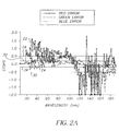
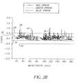
- Figures 2A and 2B evaluate the performance of two distinct capture systems: a typical motion picture color negative film and a typical high definition video camera (HD Video Rec. 709).
- Figure 2A shows exposure error curves 22, 24 and 26 for red, green and blue exposure values computed with a typical set of color negative film response curves, relative to tristimulus values computed with the 1931 CIE color-matching functions. The red, green and blue errors are measured on the y-axis, in stops. Each point on the x-axis corresponds to one of the 190 patches described in Appendix A of the aforementioned U.S. Patent No. 5,582,961.
- the solid horizontal lines 28 and 30 determine the +0.5 stop and -0.5 stop error levels, respectively, whereas the solid horizontal lines 32 and 34 determine the +1/6 stop and -1/6 stop error levels, respectively.
- Figure 2B performs the same exposure comparison, now showing exposure error curves 36, 38 and 40 for red, green and blue exposure values computed for a typical high definition video camera relative to the human visual system, represented by the 1931 CIE color-matching functions.
- the red, green and blue errors are computed according to equations 8a, 8b and 8c, respectively, with tungsten 3200 K° as the light source chosen.
- Figures 2A and 2B show that several patches, when captured by the film system or the video camera, contain large error values. This implies that a large number of colors that can be discriminated by the human visual system cannot be accurately captured by either system, with the gamut being less for video than film image capture systems. Therefore, an electronic capture device with a color gamut larger than what is currently available is highly desirable.
- a third problem, particular to electronic or hybrid capture devices known in the prior art, relates to the level of noise introduced during processing of the image signals.
- the majority of the operations performed in the image processing path involves the application of matrices and/or look-up tables (LUTs) to input image signals.
- Look-up tables require intense computational power, since the volumes of image data in applications related to the motion picture industry are, in general, very large. Matrices are less computationally intensive. Either method can introduce considerable noise to the original signals.
- the level of noise introduced depends on the magnitude of the coefficients used.
- color reproduction accuracy can be achieved in a digital camera by the combination of a set of spectral response curves modeled after all-positive color-matching functions and a color-correction matrix.
- the color correction matrix coefficients are computed in order to provide optimization of color reproduction for a unique combination of image sensor, passive optical elements and light source.
- an electronic color capture system includes an imaging section for generating a plurality of color image signals from an image, wherein the imaging section has predetermined spectral sensitivities defining its spectral response, and an optical section for separating the image into its separate color content and directing the separate color content toward the imaging section, wherein the optical section has specific spectral characteristics which define its spectral response.
- the spectral responses of the optical section and the imaging section are selected so as to cascade together to provide all-positive, symmetrical system curves modeled upon red, green and blue color matching functions representative of the human visual system.
- the color matching functions are derived from three monochromatic light sources and contain no more than three positive lobes as well as one or more negative lobes, wherein the areas under the color matching functions determined by (a) summation of all negative lobes and (b) overlap between the green and red color matching functions are minimized.
- the color image signals are processed with a color correction matrix having coefficients optimized for signal-to-noise performance for producing an output color image exhibiting an accurate color reproduction of the input image.
- This invention presents several advantages over the technology and devices in the prior art.
- One such advantage over current electronic capture systems is the accuracy of color capture, which is a result of the match between the human visual system and the unique set of spectral response curves and the correction matrix used in the invention. This implies, in the absence of any "preferred looks," an electronic image capture system having an advantage for those applications requiring highly accurate color capture - e.g. motion picture special effects.
- Another major advantage relates to the suggested physical setup of the capture device, which utilizes a set of optical filters optimized for light intensity distribution between the red and green channels (exposure optimization). The criteria for maintaining high signal-to-noise for producing the required correction matrix, and is desirable for high quality reproduction of images.
- imaging devices employing electronic sensors are well known, the present description will be directed in particular to elements forming part of, or cooperating more directly with, apparatus and method in accordance with the present invention. Elements not specifically shown or described herein may be selected from those known in the art. Certain aspects of the embodiments to be described may be provided in software. Given the system as shown and described according to the invention in the following materials, software not specifically shown, described or suggested herein that is useful for implementation of the invention is conventional and within the ordinary skill in such arts. This description focuses on the key individual elements that compose the optical path and the image processing path present according to the current invention and responsible for obtaining high color reproduction accuracy, as well as on the characterization of the response curves used according to the invention. Aspects of this invention which are common to electronic capture systems in general are well understood by those skilled in the art and require no further discussion.
- an electronic capture system is provided with spectral response curves and image processing elements which are specifically designed to obtain maximum accuracy in color reproduction.
- the method utilized for the design of the spectral response curves and the image processing path of the electronic capture device described in this invention has its foundation set on the following goals:
- Figure 3 shows an electronic capture device 100 for either still or motion pictures; therefore the device 100 may be configured as either a still or motion picture camera.
- the capture device 100 includes an optical section 110 which includes a lens 111 for forming an image that is transmitted through an optical filter array 112 to a color-selective beam splitter 114.
- the beam splitter 114 includes, e.g., a dichroic layer 114a for separating the incoming beam 116 into three spectrally separated color beams 118, 120, 122 that are directed through respective cutoff filters 124, 126, 128.
- the filtered light beams output by the optical section 110 are directed to an imaging section comprising three separate image sensors 130, 132, 134.
- the image sensors are conventional monochromatic electronic devices such as charge-coupled devices (CCD) or CMOS devices. Each sensor produces an analog color signal corresponding to the intensity of the colored light beam that is incident upon the sensor.
- the respective analog color signals from the sensors 130, 132, 134 are converted into digital signals by an analog-to-digital (A/D) converter 136 and applied to an image processing unit 138.
- the processed image signals are then stored in a storage unit 140.
- light from a light source 142 is reflected from an object 144 to the electronic capture device 100.
- the reflected light is transmitted through the lens 111 and the initial array of optical filters 112, which may be optional but preferably includes an infra-red filter 112a and a blur filter 112b.
- the filtered light traverses the beam-splitter 114, which has transmission and reflection characteristics designed such that the green content of input light is passed to the image sensor 132, the red content is passed to the image sensor 130 and the blue content is passed to the image sensor 134.
- the optical filters 124, 126 and 128 are placed between the beam splitter 114 and the image sensors 130, 132 and 134, respectively, to customize the spectral characteristics of the respective light beams.
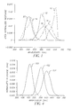
- the transmittance curves for the beam splitter 114 and the optical filters 124, 126 and 128 are designed such that the overall effect of the cascaded optical elements - for a particular "white” (i.e. color temperature) light source - is equivalent to the filtration provided by the RGB system response curves 150, 152 and 154 shown in Figure 4, as modified by the spectral responses of the respective image sensors and other elements of the optical system 110, such as the lens 111 and the optical array 112.
- the red system response curve 154 is substantially equivalent to the concatenation of the red spectral response of the beam splitter 114 and the spectral shape of the optical filter 124 with the spectral response of the image sensor 130, and so on for the other curves.
- analog image signals are formed and converted to digital image signals by the A/D converter 136.
- image-processing unit 138 a color-correction matrix is applied to the digital image signals, which are then stored in the storage unit 140.
- Figure 3 illustrates an exemplary physical configuration of the key components present according to the invention.
- Other image capture configurations of the invention are possible, e.g., configurations based on dual or single light sensors - as opposed to the three sensors shown in the example - could also be implemented by those skilled in the art.
- the imaging section may consist of a single image sensor and the color filtration would be provided by a mosaic color filter placed in front of, or on the surface of, the image sensor.
- the mosaic filter would have individual filter elements that would separate the image light into its color content.
- the spectral response of the optical section would then include the filter characteristics of the mosaic filter and the optical characteristics of other optical elements that might be in the path of the image light.
- the quality factor (q) which varies between 0.0 and 1.0 (1.0 being a perfect match and a theoretical 0.0 being an extremely poor correlation), is mathematically defined in the article (pages 567 - 568) and a method is employed to search for a set of all-positive spectral sensitivity curves that yield high q-values. It should be emphasized that one of ordinary skill in this art would understand Clapper's technique for estimating the q values, further details of which can be found in Chapter 19 of The Theory of The Photographic Process, Fourth Edition.
- Clapper points out that it is possible that more than one set of curves may have the same high quality factor and yet their performances might differ significantly from one to the other.
- the quality factor should be interpreted as a mathematical correlation coefficient and should not be used without good judgment in the process of defining a set of spectral response curves for a capture device.
- Another important point that can be observed from Clapper's results relates to the overlap between the red light and the green light sensitivity curves or for the sake of simplicity, the red and green curves.
- Sets of response curves with high quality factor values require, inevitably, a large area overlap between the red and green curves, which imposes problems of implementation and cost efficiency if an electronic capture device is to be built with such a response set.
- the spectral response curves (shown in Figure 4) are modeled after a set of color-matching functions (shown in Figure 5) that meet the following criteria:
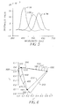
- Figure 5 depicts the color-matching function set that corresponds to the minimum summation of the negative lobe area and the red and green overlap area, under the constraint imposed by having the largest possible color-gamut.
- the curves are color balanced for a tungsten 3200 K light source and the corresponding wavelength values for the color-primaries are as follows:
- FIG. 6 The corresponding chromaticity diagram is presented in Figure 6, which shows a locus 200 of points representing the color gamut of the image capture device 100 shown in Figure 3 utilizing the spectral response curves shown in Figure 4. This gamut may be compared to the locus 210 of points corresponding to the position of pure spectrum colors, i.e., the spectral locus of all physically realizable colors.
- the optical components of the image capture system are responsible for determining the shape of spectral sensitivity curves for a given imaging system.
- a plurality of functions are used to describe optical filters, which are responsible for determining the shape of spectral sensitivity curves for a given imaging system.
- this paper emphasizes that practical systems require smooth, nonnegative functions with a small number of parameters. In particular, a feasible system requires that each filter have no more than 5 parameters.
- the set of spectral sensitivity curves is to be designed by maximizing a pre-defined measure of goodness imposed on the functions that provide a mathematical model for those filters.
- sets of three cubic spline functions and sets of functions composed of sums of Gaussians are tested.
- Quan et al. focuses on modeling the "optimum" response curves in terms of functions that are smooth, non-negative and characterized by a small number of parameters.
- no specific attempt is made to minimize the overlap area between the red and green response curves.
- a set of three all-positive symmetrical, specifically Gaussian, curves is chosen to model the color-matching functions associated with the unique set of color-primaries ⁇ R , ⁇ G , ⁇ B .
- the following set of parameters defines the set of Gaussian curves that best matches the aim set of color-matching functions.
- the system response curves shown in Figure 4 which characterize the electronic capture system represented by this invention are obtained by cascading the individual spectral sensitivity and/or spectral transmittance and/or spectral reflectance curves of any optical elements (lenses, prisms, filters, electronic sensors, among others) present in the optical path of the invention.
- Any optical filters which are part of the preferred embodiment for the invention are designed with spectral transmittance curves such that the cascading of all the optical elements which are part of the invention corresponds to a set of spectral response curves identical, aside from adjustable gain factors, to the Gaussian curves described by ⁇ ⁇ R , ⁇ ⁇ G , ⁇ ⁇ B , ⁇ R , ⁇ G , ⁇ B .
- a correction matrix is placed in the image processing path (in the image processing unit 138) of the invention.
- the match between the aim set of color-matching functions and the set of spectral response curves which characterize this invention is optimized by the unique combination of Gaussian curves parameterized by ⁇ ⁇ R , ⁇ ⁇ G , ⁇ ⁇ B , ⁇ R , ⁇ G , ⁇ B with the correction matrix.
- the nine coefficients of the 3x3-correction matrix are designed such that two error-measuring parameters are minimized.
- the first parameter consists of ⁇ E ⁇ * ab , as defined in Equation 4.
- the second parameter, ⁇ N measures the level of signal noise introduced by the correction matrix.
- M cor For a generic correction matrix, M cor , represented by:
- the parameter ⁇ N is defined as the sum of the square roots of the sum of the squares of the elements of each row in the matrix M cor which transforms the exposure signals. Mathematically this parameter ⁇ N is expressed as: where i and j represent row and column numbers, respectively, of the elements of M cor . (This parameter ⁇ N is referred to a noise-gain factor, and is described in detail in the aforementioned U.S. Patent No. 5,609,978.)
- the diagnostic patch set used for the calculation of ⁇ E ⁇ * ab and ⁇ N contains 190 patches and encompasses a large variety of hues and saturations, as well as selective neutral patches.
- the 1931 CIE chromaticity values for all 190 patches are displayed in the aforementioned Appendix A.
- Tungsten 3200 K was used as the light source.
- the light source was represented by the properly scaled spectral power distribution curve of a blackbody at a color temperature of 3200 K.
- Such configurations include techniques for directing image light of separate color content upon a single sensor, i.e., the "beam splitting" function may be performed by a color-selective component, integrally formed with the sensor, such as a color filter array (CFA or mosaic) overlying the single sensor or different color selective layers within the single sensor.
- a color-selective component integrally formed with the sensor, such as a color filter array (CFA or mosaic) overlying the single sensor or different color selective layers within the single sensor.
Landscapes
- Engineering & Computer Science (AREA)
- Multimedia (AREA)
- Signal Processing (AREA)
- Color Television Image Signal Generators (AREA)
- Processing Of Color Television Signals (AREA)
Applications Claiming Priority (2)
| Application Number | Priority Date | Filing Date | Title |
|---|---|---|---|
| US80231 | 2002-02-21 | ||
| US10/080,231 US7053935B2 (en) | 2002-02-21 | 2002-02-21 | Apparatus and method for accurate electronic color capture and reproduction |
Publications (2)
| Publication Number | Publication Date |
|---|---|
| EP1343331A2 true EP1343331A2 (fr) | 2003-09-10 |
| EP1343331A3 EP1343331A3 (fr) | 2005-01-05 |
Family
ID=27733176
Family Applications (1)
| Application Number | Title | Priority Date | Filing Date |
|---|---|---|---|
| EP03075373A Withdrawn EP1343331A3 (fr) | 2002-02-21 | 2003-02-10 | Appareil et méthode pour la capture électronique précise d'images en couleur et leur reproduction |
Country Status (3)
| Country | Link |
|---|---|
| US (1) | US7053935B2 (fr) |
| EP (1) | EP1343331A3 (fr) |
| JP (1) | JP2003284082A (fr) |
Families Citing this family (21)
| Publication number | Priority date | Publication date | Assignee | Title |
|---|---|---|---|---|
| US7570282B1 (en) * | 1998-12-09 | 2009-08-04 | Aptina Imaging Corporation | Color correction of multiple colors using a calibrated technique |
| DE60332155D1 (de) * | 2002-12-12 | 2010-05-27 | Koninkl Philips Electronics Nv | Transformationsstrukturen zur annäherung von farbabstimmungsfunktionen |
| JP3861808B2 (ja) * | 2002-12-25 | 2006-12-27 | ソニー株式会社 | 撮像装置 |
| WO2005101853A1 (fr) * | 2004-04-05 | 2005-10-27 | Mitsubishi Denki Kabushiki Kaisha | Dispositif d’imagerie |
| US20060044451A1 (en) * | 2004-08-30 | 2006-03-02 | Eastman Kodak Company | Wide angle lenslet camera |
| GB2426881B (en) * | 2005-06-01 | 2010-12-29 | Snell & Wilcox Ltd | Method and apparatus for spatial interpolation of colour images |
| DE102005048006A1 (de) * | 2005-10-06 | 2007-04-12 | Carl Zeiss Surgical Gmbh | Mikroskopiesystem und Aufnahmeverfahren zur Sichtbarmachung einer Fluoreszenz |
| KR101225060B1 (ko) * | 2006-03-08 | 2013-01-23 | 삼성전자주식회사 | 이미지 센서에서 노이즈 판단 기준을 추정하는 방법 및장치 |
| US7773127B2 (en) * | 2006-10-13 | 2010-08-10 | Apple Inc. | System and method for RAW image processing |
| US7830429B1 (en) * | 2007-07-27 | 2010-11-09 | Hewlett-Packard Development Company, L.P. | Optimizing characterization values of image capture apparatus components |
| US7940423B2 (en) * | 2007-11-30 | 2011-05-10 | Canon Kabushiki Kaisha | Generating a device independent interim connection space for spectral data |
| US20100157330A1 (en) * | 2008-12-18 | 2010-06-24 | Yue Qiao | Optimized color conversion |
| JP2012010276A (ja) * | 2010-06-28 | 2012-01-12 | Sony Corp | 画像処理装置、画像処理方法及び画像処理プログラム |
| US9332235B2 (en) * | 2013-12-10 | 2016-05-03 | Visera Technologies Company Limited | Imaging capture apparatus having plurality of image sensors generating respective image signals based on emitted light areas |
| EP4250738B1 (fr) | 2014-04-22 | 2025-12-31 | Snap-Aid Patents Ltd. | Procédé de commande d'un appareil photo d'après un traitement d'une image capturée par un autre appareil photo |
| CN104320640B (zh) * | 2014-11-12 | 2017-02-22 | 北京凌云光技术有限责任公司 | Rgb光谱响应曲线的建立方法及系统、感光像元组 |
| KR102218832B1 (ko) | 2014-12-16 | 2021-02-24 | 삼성전자주식회사 | 컬러 프린지를 제거하기 위한 이미지 처리 장치 |
| KR102255218B1 (ko) * | 2014-12-18 | 2021-05-24 | 삼성전자주식회사 | 컬러 프린지를 제거하기 위한 이미지 처리 장치 |
| CN105635701B (zh) * | 2016-01-21 | 2017-09-12 | 东莞全球鹰医疗科技有限责任公司 | 一种3ccd棱镜胶合定位成像系统及其成像方法 |
| US11199446B2 (en) * | 2016-05-30 | 2021-12-14 | Silios Technologies | Method for limiting crosstalk in an image sensor |
| WO2022267893A1 (fr) * | 2021-06-23 | 2022-12-29 | The University Of Hong Kong | Liquide colloïdal à réponse optique à changement de couleur complet |
Family Cites Families (19)
| Publication number | Priority date | Publication date | Assignee | Title |
|---|---|---|---|---|
| US3789132A (en) * | 1972-05-19 | 1974-01-29 | Bell Telephone Labor Inc | Color camera system having complete spectral characteristics |
| US4278538A (en) * | 1979-04-10 | 1981-07-14 | Western Electric Company, Inc. | Methods and apparatus for sorting workpieces according to their color signature |
| JPH0219092A (ja) * | 1988-07-07 | 1990-01-23 | Canon Inc | 色分解フィルター |
| JP2872759B2 (ja) * | 1989-06-08 | 1999-03-24 | 富士写真フイルム株式会社 | 固体撮像システム |
| US4935816A (en) * | 1989-06-23 | 1990-06-19 | Robert A. Faber | Method and apparatus for video image film simulation |
| JP3200093B2 (ja) * | 1991-07-08 | 2001-08-20 | キヤノン株式会社 | カラー画像処理装置 |
| EP0587128B1 (fr) * | 1992-09-08 | 1998-07-29 | Fuji Photo Film Co., Ltd. | Système et procédé de traitement d'images pour reproduire exactement les couleurs d'objets sur un film négatif |
| JP3316054B2 (ja) * | 1993-10-25 | 2002-08-19 | 日本放送協会 | 色補正方法および装置 |
| US5475425B1 (en) * | 1994-01-25 | 2000-07-25 | Przyborski Production | Apparatus and method for creating video ouputs that emulate the look of motion picture film |
| US5582961A (en) * | 1995-06-06 | 1996-12-10 | Eastman Kodak Company | Photographic elements which achieve colorimetrically accurate recording |
| US5609978A (en) * | 1995-06-06 | 1997-03-11 | Eastman Kodak Company | Method for producing an electronic image from a photographic element |
| US5668596A (en) * | 1996-02-29 | 1997-09-16 | Eastman Kodak Company | Digital imaging device optimized for color performance |
| JPH09321999A (ja) * | 1996-05-24 | 1997-12-12 | Fuji Photo Film Co Ltd | 色変換精度補正方法 |
| JP3624604B2 (ja) * | 1996-12-28 | 2005-03-02 | 株式会社ニコン | 撮像装置の色再現補正装置および補正方法 |
| US6269217B1 (en) * | 1998-05-21 | 2001-07-31 | Eastman Kodak Company | Multi-stage electronic motion image capture and processing system |
| JP4323043B2 (ja) * | 1999-12-28 | 2009-09-02 | 富士フイルム株式会社 | 固体撮像装置および光学フィルタ |
| JP4064038B2 (ja) * | 2000-06-09 | 2008-03-19 | 富士フイルム株式会社 | 固体撮像素子を用いた画像取得装置および画像取得方法並びにその方法を実行するためのプログラムを記録した記録媒体 |
| JP4797289B2 (ja) * | 2001-07-04 | 2011-10-19 | ソニー株式会社 | 撮像装置 |
| US6822657B2 (en) * | 2001-08-10 | 2004-11-23 | Agilent Technologies, Inc. | Method and apparatus for improving image quality in digital cameras |
-
2002
- 2002-02-21 US US10/080,231 patent/US7053935B2/en not_active Expired - Fee Related
-
2003
- 2003-02-10 EP EP03075373A patent/EP1343331A3/fr not_active Withdrawn
- 2003-02-18 JP JP2003040007A patent/JP2003284082A/ja active Pending
Also Published As
| Publication number | Publication date |
|---|---|
| EP1343331A3 (fr) | 2005-01-05 |
| US7053935B2 (en) | 2006-05-30 |
| JP2003284082A (ja) | 2003-10-03 |
| US20030156214A1 (en) | 2003-08-21 |
Similar Documents
| Publication | Publication Date | Title |
|---|---|---|
| US7053935B2 (en) | Apparatus and method for accurate electronic color capture and reproduction | |
| US20060012808A1 (en) | Image processing device, image processing method, and image processing device manufacturing method | |
| CN1732694B (zh) | 图像拾取装置和方法 | |
| EP1092323B1 (fr) | Procedes et appareils pour la caracterisation de dispositif en couleur | |
| USRE39712E1 (en) | Digital imaging device optimized for color performance | |
| Berns | The science of digitizing paintings for color-accurate image archives: a review | |
| KR20070098960A (ko) | 촬상 장치 및 촬상 소자 | |
| US9036030B2 (en) | Color calibration of an image capture device in a way that is adaptive to the scene to be captured | |
| JPH05276529A (ja) | 色温度またはホワイトバランスの調整方法及び装置 | |
| Pointer et al. | Practical camera characterization for colour measurement | |
| US8026954B2 (en) | System and computer-readable medium for automatic white balancing | |
| JP4874752B2 (ja) | デジタルカメラ | |
| EP3182691A1 (fr) | Procédé de codage de coordonnées de couleurs brutes fournies par une caméra représentant les couleurs d'une scène comportant deux éclairages différents | |
| JP2002109523A (ja) | 撮像装置、光学フィルタ群および画像データ変換装置 | |
| US20060222324A1 (en) | Imaging device | |
| US20040119860A1 (en) | Method of colorimetrically calibrating an image capturing device | |
| US7394929B2 (en) | Digital picture image color conversion | |
| JP2005278213A (ja) | 製造方法 | |
| JP4859502B2 (ja) | 撮像装置 | |
| JP2001320591A (ja) | カラーバランス調整方法および装置並びに記録媒体 | |
| JP2008085975A (ja) | 撮像素子特性評価方法および撮像素子特性評価装置 | |
| JP4003037B2 (ja) | ホワイトバランス調整装置、ホワイトバランス調整プログラム、ホワイトバランス調整方法およびディジタルカメラ | |
| EP0564125A2 (fr) | Méthode pour calibrer des dispositifs de balayage | |
| JP2007097202A (ja) | 画像処理装置 | |
| Berns | Munsell Color Science Laboratory Technical Report,“ |
Legal Events
| Date | Code | Title | Description |
|---|---|---|---|
| PUAI | Public reference made under article 153(3) epc to a published international application that has entered the european phase |
Free format text: ORIGINAL CODE: 0009012 |
|
| AK | Designated contracting states |
Kind code of ref document: A2 Designated state(s): AT BE BG CH CY CZ DE DK EE ES FI FR GB GR HU IE IT LI LU MC NL PT SE SI SK TR |
|
| AX | Request for extension of the european patent |
Extension state: AL LT LV MK RO |
|
| PUAL | Search report despatched |
Free format text: ORIGINAL CODE: 0009013 |
|
| AK | Designated contracting states |
Kind code of ref document: A3 Designated state(s): AT BE BG CH CY CZ DE DK EE ES FI FR GB GR HU IE IT LI LU MC NL PT SE SI SK TR |
|
| AX | Request for extension of the european patent |
Extension state: AL LT LV MK RO |
|
| RIC1 | Information provided on ipc code assigned before grant |
Ipc: 7H 04N 9/11 A |
|
| 17P | Request for examination filed |
Effective date: 20050506 |
|
| AKX | Designation fees paid |
Designated state(s): DE FR GB |
|
| STAA | Information on the status of an ep patent application or granted ep patent |
Free format text: STATUS: THE APPLICATION HAS BEEN WITHDRAWN |
|
| 18W | Application withdrawn |
Effective date: 20101211 |