EP1343355B2 - Intelligenter Suszeptor mit geometrisch komplex verformter Oberfläche - Google Patents
Intelligenter Suszeptor mit geometrisch komplex verformter Oberfläche Download PDFInfo
- Publication number
- EP1343355B2 EP1343355B2 EP03075510A EP03075510A EP1343355B2 EP 1343355 B2 EP1343355 B2 EP 1343355B2 EP 03075510 A EP03075510 A EP 03075510A EP 03075510 A EP03075510 A EP 03075510A EP 1343355 B2 EP1343355 B2 EP 1343355B2
- Authority
- EP
- European Patent Office
- Prior art keywords
- mesh structure
- magnetically permeable
- susceptor
- induction heating
- smart susceptor
- Prior art date
- Legal status (The legal status is an assumption and is not a legal conclusion. Google has not performed a legal analysis and makes no representation as to the accuracy of the status listed.)
- Expired - Lifetime
Links
- 238000000465 moulding Methods 0.000 title description 2
- 239000000463 material Substances 0.000 claims description 57
- 230000006698 induction Effects 0.000 claims description 47
- 238000010438 heat treatment Methods 0.000 claims description 43
- 230000004907 flux Effects 0.000 claims description 30
- 229910052751 metal Inorganic materials 0.000 claims description 19
- 239000002184 metal Substances 0.000 claims description 19
- 238000000034 method Methods 0.000 claims description 17
- 230000035699 permeability Effects 0.000 claims description 16
- 238000004519 manufacturing process Methods 0.000 claims description 14
- 239000000843 powder Substances 0.000 claims description 10
- 229910001220 stainless steel Inorganic materials 0.000 claims description 9
- 238000000137 annealing Methods 0.000 claims description 8
- UFHFLCQGNIYNRP-UHFFFAOYSA-N Hydrogen Chemical compound [H][H] UFHFLCQGNIYNRP-UHFFFAOYSA-N 0.000 claims description 5
- NPXOKRUENSOPAO-UHFFFAOYSA-N Raney nickel Chemical compound [Al].[Ni] NPXOKRUENSOPAO-UHFFFAOYSA-N 0.000 claims description 5
- 239000011248 coating agent Substances 0.000 claims description 5
- 238000000576 coating method Methods 0.000 claims description 5
- 238000005245 sintering Methods 0.000 claims description 5
- 229910052782 aluminium Inorganic materials 0.000 claims description 4
- XAGFODPZIPBFFR-UHFFFAOYSA-N aluminium Chemical compound [Al] XAGFODPZIPBFFR-UHFFFAOYSA-N 0.000 claims description 4
- 229910000907 nickel aluminide Inorganic materials 0.000 claims description 4
- 238000003754 machining Methods 0.000 claims description 3
- 238000005507 spraying Methods 0.000 claims description 3
- 238000004026 adhesive bonding Methods 0.000 claims description 2
- 238000000151 deposition Methods 0.000 claims 3
- 230000005291 magnetic effect Effects 0.000 description 22
- 241000167857 Bourreria Species 0.000 description 9
- 229910010293 ceramic material Inorganic materials 0.000 description 9
- 239000000919 ceramic Substances 0.000 description 8
- XEEYBQQBJWHFJM-UHFFFAOYSA-N Iron Chemical compound [Fe] XEEYBQQBJWHFJM-UHFFFAOYSA-N 0.000 description 7
- 239000011152 fibreglass Substances 0.000 description 6
- RTAQQCXQSZGOHL-UHFFFAOYSA-N Titanium Chemical group [Ti] RTAQQCXQSZGOHL-UHFFFAOYSA-N 0.000 description 5
- 239000000956 alloy Substances 0.000 description 5
- 230000008901 benefit Effects 0.000 description 5
- 239000002131 composite material Substances 0.000 description 5
- 239000002826 coolant Substances 0.000 description 5
- 239000012530 fluid Substances 0.000 description 5
- ISWSIDIOOBJBQZ-UHFFFAOYSA-N phenol group Chemical group C1(=CC=CC=C1)O ISWSIDIOOBJBQZ-UHFFFAOYSA-N 0.000 description 5
- 230000008569 process Effects 0.000 description 5
- 229910045601 alloy Inorganic materials 0.000 description 4
- 238000005452 bending Methods 0.000 description 4
- 229910052742 iron Inorganic materials 0.000 description 4
- 230000003647 oxidation Effects 0.000 description 4
- 238000007254 oxidation reaction Methods 0.000 description 4
- 238000012545 processing Methods 0.000 description 4
- 230000015572 biosynthetic process Effects 0.000 description 3
- 238000005266 casting Methods 0.000 description 3
- 238000007596 consolidation process Methods 0.000 description 3
- 238000013461 design Methods 0.000 description 3
- 239000010936 titanium Substances 0.000 description 3
- 229910052719 titanium Inorganic materials 0.000 description 3
- PXHVJJICTQNCMI-UHFFFAOYSA-N Nickel Chemical compound [Ni] PXHVJJICTQNCMI-UHFFFAOYSA-N 0.000 description 2
- PNEYBMLMFCGWSK-UHFFFAOYSA-N aluminium oxide Inorganic materials [O-2].[O-2].[O-2].[Al+3].[Al+3] PNEYBMLMFCGWSK-UHFFFAOYSA-N 0.000 description 2
- 238000013459 approach Methods 0.000 description 2
- 230000000712 assembly Effects 0.000 description 2
- 238000000429 assembly Methods 0.000 description 2
- 230000000694 effects Effects 0.000 description 2
- 239000003302 ferromagnetic material Substances 0.000 description 2
- 239000000835 fiber Substances 0.000 description 2
- 239000011159 matrix material Substances 0.000 description 2
- 238000005259 measurement Methods 0.000 description 2
- 239000000203 mixture Substances 0.000 description 2
- 238000012986 modification Methods 0.000 description 2
- 230000004048 modification Effects 0.000 description 2
- 230000009467 reduction Effects 0.000 description 2
- 230000004044 response Effects 0.000 description 2
- 239000007921 spray Substances 0.000 description 2
- XLYOFNOQVPJJNP-UHFFFAOYSA-N water Substances O XLYOFNOQVPJJNP-UHFFFAOYSA-N 0.000 description 2
- 239000013585 weight reducing agent Substances 0.000 description 2
- RYGMFSIKBFXOCR-UHFFFAOYSA-N Copper Chemical compound [Cu] RYGMFSIKBFXOCR-UHFFFAOYSA-N 0.000 description 1
- 229910052692 Dysprosium Inorganic materials 0.000 description 1
- 229910000831 Steel Inorganic materials 0.000 description 1
- 238000005219 brazing Methods 0.000 description 1
- 230000008859 change Effects 0.000 description 1
- 239000010941 cobalt Substances 0.000 description 1
- 229910017052 cobalt Inorganic materials 0.000 description 1
- GUTLYIVDDKVIGB-UHFFFAOYSA-N cobalt atom Chemical compound [Co] GUTLYIVDDKVIGB-UHFFFAOYSA-N 0.000 description 1
- 230000006835 compression Effects 0.000 description 1
- 238000007906 compression Methods 0.000 description 1
- 238000001816 cooling Methods 0.000 description 1
- 229910052802 copper Inorganic materials 0.000 description 1
- 239000010949 copper Substances 0.000 description 1
- 229910052593 corundum Inorganic materials 0.000 description 1
- 230000008878 coupling Effects 0.000 description 1
- 238000010168 coupling process Methods 0.000 description 1
- 238000005859 coupling reaction Methods 0.000 description 1
- 238000005336 cracking Methods 0.000 description 1
- 230000001351 cycling effect Effects 0.000 description 1
- 238000010586 diagram Methods 0.000 description 1
- 238000009713 electroplating Methods 0.000 description 1
- 230000007613 environmental effect Effects 0.000 description 1
- 238000009432 framing Methods 0.000 description 1
- 239000003292 glue Substances 0.000 description 1
- 230000020169 heat generation Effects 0.000 description 1
- 230000006872 improvement Effects 0.000 description 1
- 230000001939 inductive effect Effects 0.000 description 1
- 239000011261 inert gas Substances 0.000 description 1
- 230000002401 inhibitory effect Effects 0.000 description 1
- 238000003780 insertion Methods 0.000 description 1
- 230000037431 insertion Effects 0.000 description 1
- 239000012212 insulator Substances 0.000 description 1
- 229910001004 magnetic alloy Inorganic materials 0.000 description 1
- 229910052759 nickel Inorganic materials 0.000 description 1
- 230000001681 protective effect Effects 0.000 description 1
- 230000002787 reinforcement Effects 0.000 description 1
- 239000011347 resin Substances 0.000 description 1
- 229920005989 resin Polymers 0.000 description 1
- 238000007789 sealing Methods 0.000 description 1
- 238000004904 shortening Methods 0.000 description 1
- 229910052710 silicon Inorganic materials 0.000 description 1
- 239000010703 silicon Substances 0.000 description 1
- HBMJWWWQQXIZIP-UHFFFAOYSA-N silicon carbide Chemical compound [Si+]#[C-] HBMJWWWQQXIZIP-UHFFFAOYSA-N 0.000 description 1
- 229910010271 silicon carbide Inorganic materials 0.000 description 1
- 238000004901 spalling Methods 0.000 description 1
- 239000010935 stainless steel Substances 0.000 description 1
- 239000010959 steel Substances 0.000 description 1
- 229910001845 yogo sapphire Inorganic materials 0.000 description 1
Images




Classifications
-
- H—ELECTRICITY
- H05—ELECTRIC TECHNIQUES NOT OTHERWISE PROVIDED FOR
- H05B—ELECTRIC HEATING; ELECTRIC LIGHT SOURCES NOT OTHERWISE PROVIDED FOR; CIRCUIT ARRANGEMENTS FOR ELECTRIC LIGHT SOURCES, IN GENERAL
- H05B6/00—Heating by electric, magnetic or electromagnetic fields
- H05B6/02—Induction heating
- H05B6/10—Induction heating apparatus, other than furnaces, for specific applications
- H05B6/105—Induction heating apparatus, other than furnaces, for specific applications using a susceptor
-
- B—PERFORMING OPERATIONS; TRANSPORTING
- B29—WORKING OF PLASTICS; WORKING OF SUBSTANCES IN A PLASTIC STATE IN GENERAL
- B29C—SHAPING OR JOINING OF PLASTICS; SHAPING OF MATERIAL IN A PLASTIC STATE, NOT OTHERWISE PROVIDED FOR; AFTER-TREATMENT OF THE SHAPED PRODUCTS, e.g. REPAIRING
- B29C33/00—Moulds or cores; Details thereof or accessories therefor
- B29C33/02—Moulds or cores; Details thereof or accessories therefor with incorporated heating or cooling means
- B29C33/06—Moulds or cores; Details thereof or accessories therefor with incorporated heating or cooling means using radiation, e.g. electro-magnetic waves, induction heating
-
- H—ELECTRICITY
- H05—ELECTRIC TECHNIQUES NOT OTHERWISE PROVIDED FOR
- H05B—ELECTRIC HEATING; ELECTRIC LIGHT SOURCES NOT OTHERWISE PROVIDED FOR; CIRCUIT ARRANGEMENTS FOR ELECTRIC LIGHT SOURCES, IN GENERAL
- H05B2206/00—Aspects relating to heating by electric, magnetic, or electromagnetic fields covered by group H05B6/00
- H05B2206/02—Induction heating
- H05B2206/023—Induction heating using the curie point of the material in which heating current is being generated to control the heating temperature
Definitions
- the present invention relates to the use of induction heating systems, more particularly, to the use of smart susceptors to selectively heat a part or parts during a manufacturing process.
- induction heating processes may be carried out using any material that is electrically conductive and that generates heat when exposed to an electromagnetic flux field.
- induction heating is used to directly heat an electrically conductive part during a manufacturing process.
- the electromagnetic flux field can be generated by an electromagnetic coil that surrounds the part and is supplied with alternating, or oscillating, electrical current from a power source.
- the induction heating process typically requires the use of a susceptor that encapsulates the part.
- Susceptors are not only electrically conductive, but also have a high thermal conductivity for a more efficient and thorough heating of the part. Therefore, manufacturing processes requiring localized heating, relatively quick heat-up and cool-down times, a more efficient use of power, or customized thermal properties that enable fabrication, benefit from induction heating processes that use susceptors.
- a select type of susceptor often referred to as a “smart susceptor” is constructed of a material, or materials, that generate heat efficiently until reaching a threshold, or Curie, temperature.
- a threshold or Curie
- the magnetic permeability of those portions drops precipitously.
- the drop in magnetic permeability has two effects, it limits the generation of heat by those portions at the Curie temperature, and it shifts the magnetic flux to the lower temperature portions causing those portions below the Curie temperature to more quickly heat up to the Curie temperature.
- Matsen discloses an induction heating workcell 10 that includes a pair of ceramic dies 20, 22 mounted within a pair of strongbacks 24, 26 .
- a pair of cavities 42, 44 defined by the dies hold respective ones of a pair of tool inserts 46, 48 .
- a retort 60 is positioned between the tool inserts and includes a pair of susceptor sheets sandwiching a pair of metal, or composite, part panels.
- the tool inserts define a contoured forming surface 58 that has a shape corresponding to the desired shape of the upper and lower mold line surfaces of the completed part.
- An induction coil 35 is embedded into the dies and surrounds the cavities, tool inserts and the retort.
- Suction pressure can be used to hold the susceptor halves to the dies when handling the dies before the start of the process.
- the retort is heated to forming or consolidation temperature by energizing the induction coil which generates an electromagnetic flux field.
- the flux field causes the susceptor plates to generate heat, while the dies and tool inserts have a relatively low magnetic permeability and therefore generate little heat.
- Internal tooling pressure is used to hold the susceptors against the dies during processing. This pressure is either supplied by sealing around the perimeter of the dies or using pressurized bladders. The application of heat and pressure is continued until the metal part panels are properly brazed, or formed, or the resin in the composite panels is properly distributed to form the completed part.
- the susceptor may be custom tailored to the desired operating temperature by using different alloy materials such as cobalt/iron, nickel/iron, iron/silicon, or amorphous or crystalline magnetic alloys.
- the susceptor can be designed to have several different operating temperatures by using multiple layers of different alloys that are tuned to different Curie temperatures.
- the smart susceptor may be constructed of a pair of metal sheets that are cold or hot formed so as to define an inner mold surface that corresponds to the desired part surface.
- Each formed metal sheet is positioned in the cavity of a respective one of the dies so that the dies support the formed metal sheets.
- the susceptor sheets generate heat and a vacuum pressure is applied to conform the part panels to the inner mold surface defined by the formed metal sheets.
- the metal sheets used for the susceptor have forming limits which in turn tend to limit the complexity of the mold surface that can be defined by the metal sheets of the susceptor.
- an induction heating device for the formation of geometrically complex parts. More particularly, it would be advantageous to have a system for forming a susceptor mold surface having a complex geometry, thereby allowing the manufacture of geometrically complex parts.
- the present invention addresses the above needs and achieves other advantages by providing an induction heating device for manufacturing a part, including a geometrically complex part, by heating the part to a predetermined temperature.
- the induction heating device includes an induction coil connected to an electrical power supply for generating an electromagnetic flux field.
- a smart susceptor of the heating device is positioned in the electromagnetic flux field and includes a magnetically permeable material supported by a mesh structure.
- the magnetically permeable material generates heat in response to the flux field.
- the mesh structure provides support for the magnetically permeable material and closely conforms to the desired outer geometry of the part.
- the magnetically permeable material may be applied as a powder to the mesh using a hot spray gun, allowing tight conformance of the susceptor to the part geometry while avoiding forming limits of sheet metal susceptors.
- the induction heating device includes an electrical power supply, an induction coil and a smart susceptor.
- the induction coil is operably connected to the electrical power supply and is capable of generating an electromagnetic flux field from the electrical power.
- the smart susceptor is positioned in the electromagnetic flux field.
- the smart susceptor includes a magnetically permeable material responsive to the electromagnetic flux to generate heat.
- the smart susceptor includes a mesh structure supporting the magnetically permeable material. The mesh structure and the magnetically permeable material conform to at least a portion of the part so as to be capable of receiving the portion of the part and heating the portion of the part as the magnetically permeable material is heated.
- the mesh structure may be constructed of wire capable of withstanding the heat generated by the electromagnetic flux.
- the mesh structure may be constructed of 0,500 mm (0.02 inch) thick stainless steel wire.
- the mesh structure may also be constructed of magnetically permeable wire, such as a smart susceptor alloys to improve inductive heat generation.
- the magnetically permeable material and mesh structure may define a cavity that conforms to all of the part.
- the mesh structure includes a pair of separable portions that are combinable to define the cavity.
- the induction heating device further includes a die having a pair of die portions wherein each of the separable portions of the mesh structure are attached to a respective one of the die portions. In this manner, the die is configured to hold the separable portions of the mesh structure together so as to define the cavity.
- the present invention includes a method of manufacturing a smart susceptor for heating a part in response to the application of a magnetic flux field.
- the method of manufacturing includes providing a model having an outer geometry similar to that of the part.
- the model can be machined from richlite or aluminum.
- a mesh screen is draped over the part and conformed to the outer geometry of the model such as by tacking or gluing the mesh screen to the outer geometry of the model.
- Magnetically permeable material is deposited on the mesh screen and the mesh screen, with the permeable material, is released from the model.
- the magnetically permeable material may be developed by thermally spraying a magnetically permeable powder onto the mesh screen.
- the screen and powder are bright annealed and sintered to consolidate the combination.
- such bright annealing may occur in a hydrogen gas furnace.
- the consolidated powder and screen may be thermally sprayed on both sides with a nickel aluminide coating to protect against oxidation.
- the present invention has several advantages.
- the use of the mesh screen and thermally sprayed, magnetically permeable powder allows the smart susceptor to be molded to geometrically complex parts, overcoming the forming limitations of previously used metal sheets.
- the flexible weaves of mesh closely drape to the geometrically complex parts while providing support for the magnetically permeable material to avoid failure during handling and processing.
- Increased complexity of part geometry allows a reduction in the number of parts used in assemblies, with a concomitant cost and weight reduction.
- Hydrogen gas furnace annealing reduces oxidation in the mesh and sprayed powder material, while the increased temperature increases the density of the material.
- the present invention includes an induction heating workcell 10 , as shown in Figure 1 .
- the workcell includes an upper die 11 mounted within an upper strongback 13 and a lower die 12 mounted within lower strongback 14 .
- the strongbacks are each threaded onto four threaded column supports, or jackscrews 15 allowing adjustment of the relative positions of the dies and strongbacks.
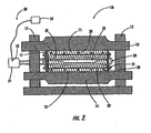
- the dies 11, 12 define a die cavity 22 that is shaped to hold a smart susceptor 34 that, in turn, surrounds a part, including a geometrically complex part 60 , such as a titanium part for an aircraft, as shown in Figures 2 and 3 .
- a plurality of induction coils 26 are embedded in the die and surround the susceptor 34 . When energized, the coils 26 create a magnetic flux field that causes the susceptor 34 to generate heat so as to perform a step in manufacturing the part 60 , such as forming a metal part, or consolidating a composite part.
- the induction heating workcell 10 further includes a set of clamping bars 16 that hold the dies in place against the strongbacks 13, 14 .
- the strongbacks provide a rigid, flat backing surface for the upper and lower dies 11, 12 which prevents the dies from bending and cracking during the manufacturing operation. Additionally, the strongbacks serve as stiff plates that keep the dies together and accurately positioned.
- the strongbacks may be constructed of steel, aluminum, or any other material capable of handling the loads present during forming or consolidation. Preferably, nonmagnetic materials are used to prevent distortion of the magnetic fields produced by the induction coil 26 .
- the dies 11, 12 themselves may be strong enough to withstand the loads present during forming or consolidation. In the embodiment depicted in Figures 1 and 2 , the strongbacks have a rectangular box shape, but may be varied in shape and size to accommodate a myriad of desired die sizes and shapes.
- Each of the dies 11, 12 includes a rectangular block of ceramic material 23 reinforced by a set of fiberglass rods 20 and a set of support plates 17 .
- the support plates are preferably a set of phenolic boards arranged in the shape of a rectangular box framing each ceramic block 23 .
- the phenolic boards 17 serve as containment walls during casting of the ceramic blocks 23 and also provide reinforcement during the subsequent induction heating process.
- the fiberglass rods 20 extend longitudinally in a first array, and transversely in a second array, so as to form a grid through each ceramic material block 23 .
- the ends of the fiberglass rods are threaded and extend through respective, opposing ones of the phenolic boards 17 .
- the grid is embedded into the ceramic block 23 by extending the fiberglass rods 20 through the phenolic boards 17 before casting the ceramic material block 23 .
- a set of nuts 21 are placed on the threaded ends of the fiberglass rods and are tightened so as apply a compressive load on the phenolic boards 17 .
- the compressive load on the boards results in a pre-stressed, compressive load on the ceramic material block 23 .
- the pre-stressed compressive load cancels the tensile loads developed during the induction heating process. Maintaining the ceramic block in compression is advantageous due to the poor tensile properties of ceramic materials.
- Other materials may be used to construct the material block 23 , but ceramic (specifically Ceradyne 120) is preferred because it is a thermal insulator and has a low coefficient of thermal expansion.
- the low coefficient of thermal expansion allows the block to be subjected to steep thermal gradients without spalling of the material.
- the ceramic serves to insulate the die cavity 22 against heat loss, conserving the heat generated by the susceptor 34 and shortening the cycling times for heating and cooling the part 60 . Further, such characteristics provide additional flexibility in the design of thermal cycles for various types of parts, resulting in an overall performance improvement.
- the induction coils 26 are also embedded into the ceramic material blocks 23 during casting and are positioned between the fiberglass rods 20 and surround the die cavity 22 , as shown in Figures 1-3 .
- the coils 26 are fabricated from 25,4 mm (1 inch) diameter, 1,59 mm (0.0625 inch) wall thickness, round copper tubing which is lightly drawn.
- the preferred lightly drawn condition of the tubing enables precision bending by numerical bending machines, as is known to those of skill in the art. Numerical bending of the tubes allows accurate placement of the tubing around the cavity 22 , which is important due to the need to evenly distribute the electromagnetic flux.
- the coils 26 also remove thermal energy by serving as a conduit for a coolant fluid, such as water.
- the coils 26 After being bent and embedded, the coils 26 include straight tubing sections 27 connected by flexible tubing sections 28 .
- the flexible tubing sections connect the straight tubing sections 27 and also allow the dies 11, 12 to be separated.
- the thickness of the cast ceramic between the susceptor 34 and the coils 26 is about ? of an inch, which is sufficient to support the temperature gradient between the heated susceptor and the water-cooled coils.
- Figure 3 illustrates the close positioning of the coils along the contours of the die cavity 22 , and the susceptor 34 contained therein. The accurate placement of the tubing of the coils 26 around the cavity promotes uniformity in the amount of heat generated by the magnetic flux field, and the amount of heat removed by flow of the coolant fluid.
- the induction coils 26 are connected to a temperature control system that includes a power supply 51 , a controlling element 52 , a sensor 53 and, optionally, a fluid coolant supply (not shown).
- the power supply 51 supplies an oscillating current, preferably at 3 KHz, to the coils 26 which causes the coils to generate the electromagnetic flux field.
- the fluid coolant supply supplies water to the induction coils 26 for circulation through the coils and the removal of thermal energy from the dies 11, 12 .
- the sensor 53 is capable of measuring the power supplied by the power supply 51 in order to control the temperature of the part. Alternatively, or in addition to measuring the power supply, the sensor 53 includes a voltmeter that can measure the voltage drop across the induction coils 26 .
- the controlling element gathers the power supply, or voltage measurements from the sensor 53 and uses the measurements in a feedback loop to adjust the power being supplied by the power supply 51 .
- the controlling element can include hardware, software, firmware, or a combination thereof that is capable of using feedback to adjust the power supply 51 .
- the susceptor 34 of the present invention is a layer, or sheet, of magnetically permeable material positioned along the inside surface of the die cavity 22 .
- the die cavity itself is shaped to roughly conform to the shape of the susceptor 34 so as to provide support for the susceptor.
- the upper die 11 defines a portion of the cavity 22 that has a shape with multiple contours
- the lower die 12 defines a planar shape. It should be noted that other, more or less complex, shapes can be defined by the contours of both the upper and lower die portions of the cavity 22 and the depicted embodiment should not be viewed as limiting.
- Preferred magnetically permeable materials for constructing the susceptor 34 include ferromagnetic materials that have an approximately 10 fold decrease in magnetic permeability when heated to a temperature higher than a critical, or Curie, temperature. Such a large drop in permeability at the critical temperature promotes temperature control of the susceptor and, as a result, temperature control of the part being manufactured.
- Ferromagnetic materials include the five elements Fe, Co, Ni, Gd and Dy, and alloys of those elements.
- the die cavity may also be coated with a protective liner 24 for improved durability of the dies 11, 12 against wear caused by insertion and removal of the susceptors and against heat generated by the susceptors.
- a protective liner 24 for improved durability of the dies 11, 12 against wear caused by insertion and removal of the susceptors and against heat generated by the susceptors.
- Preferred materials for the liner include NEXTEL (Al 2 O 3 ) fiber with an alumina-silicate or alumina matrix, or silicon carbide fibers in a silcon carbide matrix, a total of about 2,54 mm (0.100 inches) thick.
- the susceptor 34 in the embodiment depicted in Figure 3 includes upper and lower portions that are receivable into the cavity 22 defined by the upper and lower dies 11, 12 . It should be noted that the susceptor can have several portions, each contacting a respective portion of the part.
- the susceptor 34 of the present invention is a thermally sprayed, smart susceptor that includes a mesh structure 36 supporting a magnetically permeable, thermally sprayed material 37 and optionally including a nickel aluminide coating 38 , as shown in Figure 4 .
- the mesh structure 36 is preferably a wire mesh constructed of stainless steel, or of a metal having the same composition as the thermally sprayed material 37 that can withstand the temperature and other environmental factors associated with heating and forming of the part 60 .
- the mesh structure 36 provides a skeleton, or support structure, that holds together the sprayed material 37 .
- the wire mesh structure 36 is a very flexible mesh weave that can closely drape to the shape of a model worked or machined to the contours of the desired final part geometry.
- the mesh structure 36 is comprised of .020 inch thick, 300 series stainless steel wire.
- the mesh structure 36 should have sufficiently sized interstices 40 between its wires 39 to allow interdigitation of the sprayed material 37 within the mesh structure, while at the same time providing support for the sprayed material.
- the opening size of the mesh is approximately five times the wire diameter. For instance, a 0,500 mm (0.020 inch) wire would have a 2,54 mm (0.100 inch) mesh opening.
- the preferred method of constructing the smart susceptor 34 includes machining, or forming, a model of the desired part geometry from richlite or aluminum.
- the mesh structure 36 is draped over the contours of the model and may be tacked, glued, or otherwise attached, to the surface of the model.
- the material 37 starts in a powder form and is heated and sprayed from a plasma spray gun onto the mesh-covered part model until the sprayed material reaches a desired thickness.
- the susceptor 34 is released from the model by removal of the glue or tacks and is subjected to a bright annealing and sintering operation to consolidate the wire mesh structure 36 with the thermally sprayed material 37 .
- the annealing and sintering is performed in a hydrogen gas furnace so as to reduce oxidation in the susceptor and to increase the density of the susceptor.
- a nickel aluminide coating 38 is also thermally sprayed on both sides of the susceptor 34 after completion of the annealing and sintering operation.
- composition of the thermally sprayed material 37 and wire mesh structure 36 can be varied to approximately match the desired range of operation temperature(s) of the smart susceptor 34 , as described in U.S. Patent No. 5,728,309 to Matsen et al..
- Matsen describes some of the various alloys, and other materials, that exhibit smart susceptor characteristics and their respective Curie temperatures in column 13, Tables 1 and 2.
- the process of heating and forming the part includes inserting sheets of titanium, or other metal or composite, into the cavity 22 defined by the upper and lower dies 11, 12 and between the upper and lower portions of the smart susceptor 34 supported therein, when the dies are spaced apart along the threaded column supports 15 .
- the dies 11, 12 may be removed from the column supports.
- the dies 11, 12 are then brought together by movement along the column supports 15 until the part sheets and the susceptor 34 are enclosed in the cavity 22 and the cavity is sealed.
- the temperature controller 50 allows the power supply 51 to supply a predetermined amount of power, as shown graphically in Figure 8B .
- the power is supplied to the induction coils 26 causing an oscillating current in the coils which generates an electromagnetic flux field.
- the flux field depicted as flux lines 100 , travel directly through the ceramic material 23 of the lower die 12 due to its lack of magnetic permeability and couple with the magnetically permeable material of the susceptor 34 . Coupling with the magnetic flux field induces eddy currents in the susceptor, which, in turn, results in the generation of heat.
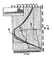
- the heat increases the temperature of the susceptor which, being adjacent to the titanium sheets of the part 60 and trapped therewith in the cavity 22 of thermally insulative ceramic material 23 , results in a temperature increase of the part, as shown by the thermocouple readings 102 of Figure 7 .
- the differences in the thermocouple readings are a result of different locations of the thermocouples.
- the average temperature of the part 60 increases at a roughly steady rate, with the aforementioned variances between part locations, until a portion 41 , or portions, of the susceptor 34 reach the Curie temperature.
- the temperature of the dies 11, 12 and induction coils 26 is kept relatively low by a supply of the coolant fluid through the tubes of the induction coils.
- those portions of the susceptor experience a sudden drop in magnetic permeability, wherein the permeability approaches unity, as shown in Figure 8A .
- the sudden drop in magnetic permeability results in a distortion of the magnetic flux generated by the induction coils 26 which moves out of the impermeable area of the susceptor 34 , as shown by the flux lines 100 of Figure 6A and 6B .
- the remaining portions of the susceptor continue to receive flux and generate heat, and may even produce more heat due to the magnetic flux being pushed out of the portions at the Curie temperature and drawn into the remaining portions of the susceptor.
- the entire susceptor 34 reaches the Curie temperature and experiences a drop in magnetic permeability.
- the decrease in magnetic permeability of the susceptor also coincides with a decrease in the inductance of the coil and the amount of energy absorbed by the part 60 , as shown in Figure 8B .
- the sensor 53 detects an increase in the voltage (and/or applied power) of the power supply 51 .
- the voltage rise therefore, can be related to the permeability drop, which, in turn, relates to the global temperature of the susceptor 34 and the part 60 .
- FIG. 7 shows voltage readings 101 and power readings 103 begin to rise as the thermocouple readings 102 begin to approach the Curie temperature.
- the voltage readings 101 begin to flatten out once all of the thermocouples are at the Curie temperature.
- the controlling element 52 detects the sudden change in voltage using the sensor 53 and can, as desired, maintain, raise, or lower the voltage of the power supply 51 without the need for thermocouples, or other direct temperature sensing devices.
- the range of temperature control is about "10 EF over a 20 EF window around the Curie point.
- Other aspects of the temperature control system are described in U.S. Patent Application No. 10/094,560 entitled "System and Method for Controlling an Induction Heating Process".
- the titanium part 60 is formed due to the internal pressure supplied by inert gas, as shown by the pressure arrows 104 of Figure 3 .
- the smart susceptor 34 in one embodiment is a mesh screen 36 supporting a thermally sprayed material 37 that has been closely conformed to the shape of the desired part geometry.
- the pressure of the air trapped between the titanium sheets increases and forces the sheets away from each other and against the complex molding surfaces of the susceptor. Air between the dies 11, 12 and the part 60 is allowed to escape through vent holes (not shown) in the dies so as to avoid inhibiting formation of the part.
- the present invention has several advantages.
- the use of the mesh screen 36 and thermally sprayed, magnetically permeable powder material 37 allows the smart susceptor to be molded to geometrically complex parts, overcoming the forming limitations of previously used metal sheet susceptors.
- the flexible weaves of mesh 36 closely drape to the geometrically complex parts while providing support for the magnetically permeable material 37 to avoid failure during handling and processing.
- Increased complexity of part geometry allows a reduction in the number of parts used in assemblies, with a concomitant cost and weight reduction.
- Hydrogen gas furnace annealing reduces oxidation in the mesh and sprayed powder material, while the increased temperature increases the density of the material.
- the mesh weave 36 can be used to support flexible susceptor material 37 that has been deposited using other processes, such as electroplating. Therefore, it is to be understood that the invention is not to be limited to the specific embodiments disclosed and that modifications and other embodiments are intended to be included within the scope of the appended claims. Although specific terms are employed herein, they are used in a generic and descriptive sense only and not for purposes of limitation.
Landscapes
- Physics & Mathematics (AREA)
- Electromagnetism (AREA)
- Health & Medical Sciences (AREA)
- Toxicology (AREA)
- Engineering & Computer Science (AREA)
- Mechanical Engineering (AREA)
- General Induction Heating (AREA)
- Heating, Cooling, Or Curing Plastics Or The Like In General (AREA)
Claims (27)
- Induktionsheizvorrichtung (10) zur Herstellung eines Teils durch Erhitzen des Teils auf eine vorbestimmte Temperatur, wobei die Induktionsheizvorrichtung umfasst:eine Induktionsspule (26), die in der Lage ist, ein elektromagnetisches Flussfeld zu erzeugen; undeinen intelligenten Suszeptor (34), welcher in dem elektromagnetischen Flussfeld angeordnet ist, wobei der intelligente Suszeptor ein magnetisch durchlässiges Material aufweist, welches auf das elektromagnetische Flussfeld reagierend Wärme erzeugt;wobei die Induktionsheizvorrichtung dadurch gekennzeichnet ist,dass der intelligente Suszeptor mit einer Maschenstruktur (36) versehen ist, welche das magnetisch durchlässige Material unterstützt, wobei sich die Maschenstruktur und das magnetisch durchlässige Material (37) an mindestens einen Abschnitt des Teils anpassen, um so in der Lage zu sein, den Abschnitt des Teils aufzunehmen und den Abschnitt des Teils zu erwärmen, während das magnetisch durchlässige Material erwärmt wird, wobei die das magnetisch durchlässige Material unterstützende Maschenstruktur ein flexibles Material aufweist, welches zu geometrisch komplexen Teilen zu formen ist.
- Induktionsheizvorrichtung nach Anspruch 1, wobei die Maschenstruktur aus Draht hergestellt ist, der geeignet ist, der durch den elektromagnetischen Fluss erzeugten Wärme standzuhalten.
- Induktionsheizvorrichtung nach Anspruch 1, wobei die Maschenstruktur aus rostfreiem Stahldraht hergestellt ist.
- Induktionsheizvorrichtung nach Anspruch 3, wobei es sich bei dem rostfreien Stahldraht um einen 0,51 mm (0,02 Inch) dicken rostfreien Stahldraht handelt.
- Induktionsheizvorrichtung nach Anspruch 1, wobei die Maschenstruktur aus einem Material hergestellt ist, welches mindestens eine zehnfache Verkleinerung der Permeabilität aufweist, wenn eine Curie-Temperatur überschritten wird.
- Induktionsheizvorrichtung nach Anspruch 1, wobei das magnetisch durchlässige Material und die Maschenstruktur einen Hohlraum (22) definieren, der sich an alles von dem Teil anpasst.
- Induktionsheizvorrichtung nach Anspruch 6, wobei die Maschenstruktur mindestens zwei trennbare Abschnitte aufweist, wobei die trennbaren Abschnitte kombinierbar sind, um den Hohlraum zu definieren.
- Induktionsheizvorrichtung nach Anspruch 7, zusätzlich eine Matrize aufweisend, die mindestens zwei Matrizenabschnitte (11, 12) besitzt, und wobei jeder der trennbaren Abschnitte der Maschenstruktur an einen entsprechenden Matrizenabschnitt der Matrizenabschnitte angebracht ist, wobei die Matrize ausgestaltet ist, um die trennbaren Abschnitte der Maschenstruktur zusammenzuhalten, um so den Hohlraum zu definieren.
- Induktionsheizvorrichtung nach Anspruch 1, die weiterhin eine elektrische Stromversorgung (51) aufweist und wobei die Induktionsspule funktionsmäßig mit der elektrischen Stromversorgung verbunden ist.
- Verfahren zur Herstellung eines intelligenten Suszeptors zur Verwendung in der Induktionsheizvorrichtung nach einem der Ansprüche 1-9, wobei das Verfahren umfasst:Bereitstellen eines Modells, welches eine äußere Geometrie aufweist, die zumindest einem Abschnitt von dem Teil ähnelt;Drapieren einer flexiblen Maschenabschirmung über dem Teil und Anpassen der flexiblen Maschenabschirmung an die Außengeometrie des Modells;Aufbringen des magnetisch durchlässigen Materials auf die Maschenabschirmung; undAblösen der Maschenabschirmung und des magnetisch durchlässigen Materials von dem Modell.
- Verfahren nach Anspruch 10, wobei das Bereitstellen des Modells eine maschinelle Herstellung des Modells aus Richlite aufweist.
- Verfahren nach Anspruch 10, wobei das Bereitstellen des Modells eine maschinelle Herstellung des Modells aus Aluminium aufweist.
- Verfahren nach Anspruch 10, wobei das Anpassen der Maschenabschirmung ein Heften der Maschenabschirmung an die äußere Geometrie des Modells aufweist.
- Verfahren nach Anspruch 10, wobei das Anpassen der Maschenabschirmung ein Kleben der Maschenabschirmung an die äußere Geometrie des Modells aufweist.
- Verfahren nach Anspruch 10, wobei das Aufbringen des magnetisch durchlässigen Metalls thermisches Spritzen von magnetisch durchlässigem Metallpulver auf die Schirmung aufweist.
- Verfahren nach Anspruch 15, wobei das Aufbringen des magnetisch durchlässigen Metalls weiterhin thermisches Spritzen eines Nickel-Aluminid-Pulvers und Ausbilden einer äußeren Beschichtung auf der Schirmung aufweist.
- Verfahren nach Anspruch 10, welches weiter Sintern und Tempern des magnetisch durchlässigen Materials nach dem Ablösen der Maschenschirmung aufweist.
- Verfahren nach Anspruch 17, wobei das Sintern und Tempern in einer Wasserstoffgasbrennkammer durchgeführt werden.
- Intelligenter Suszeptor, welcher durch das Verfahren nach einem der Ansprüche 10-18 hergestellt wurde.
- Intelligenter Suszeptor nach Anspruch 19, wobei die Maschenstruktur aus Draht hergestellt ist, welcher geeignet ist, der Wärme standzuhalten, die durch den elektromagnetischen Fluss erzeugt wird.
- Intelligenter Suszeptor nach Anspruch 19, wobei die Maschenstruktur aus rostfreiem Stahldraht hergestellt ist.
- Intelligenter Suszeptor nach Anspruch 21, wobei es sich bei dem rostfreien Stahldraht um einen 0,51 mm (0,02 Inch) dicken rostfreien Stahldraht handelt.
- Intelligenter Suszeptor nach Anspruch 19, wobei die Maschenstruktur aus einem magnetisch durchlässigen Material hergestellt ist.
- Intelligenter Suszeptor nach Anspruch 19, wobei das magnetisch durchlässige Material eine Nickel-Aluminid-Beschichtung aufweist.
- Intelligenter Suszeptor nach Anspruch 19, wobei das magnetisch durchlässige Material und die Maschenstruktur einen Hohlraum bilden, der sich an alles des Teils anpasst.
- Intelligenter Suszeptor nach Anspruch 25, wobei die Maschenstruktur mindestens zwei trennbare Abschnitte aufweist, wobei die beiden trennbaren Abschnitte kombinierbar sind, um den Hohlraum zu definieren.
- Intelligenter Suszeptor nach Anspruch 26, der ferner eine Matrize umfasst, die mindestens zwei Matrizenabschnitte besitzt, und wobei jeder der trennbaren Abschnitte der Maschenstruktur an einem entsprechenden Matrizenabschnitt der Matrizenabschnitte angebracht ist, wobei die Matrize ausgestaltet ist, um die trennbaren Abschnitte der Maschenstruktur zusammenzuhalten, so dass der Hohlraum definiert wird.
Applications Claiming Priority (2)
| Application Number | Priority Date | Filing Date | Title |
|---|---|---|---|
| US10/094,494 US6566635B1 (en) | 2002-03-08 | 2002-03-08 | Smart susceptor having a geometrically complex molding surface |
| US94494 | 2002-03-08 |
Publications (4)
| Publication Number | Publication Date |
|---|---|
| EP1343355A2 EP1343355A2 (de) | 2003-09-10 |
| EP1343355A3 EP1343355A3 (de) | 2003-12-17 |
| EP1343355B1 EP1343355B1 (de) | 2006-04-26 |
| EP1343355B2 true EP1343355B2 (de) | 2009-09-09 |
Family
ID=22245491
Family Applications (1)
| Application Number | Title | Priority Date | Filing Date |
|---|---|---|---|
| EP03075510A Expired - Lifetime EP1343355B2 (de) | 2002-03-08 | 2003-02-20 | Intelligenter Suszeptor mit geometrisch komplex verformter Oberfläche |
Country Status (4)
| Country | Link |
|---|---|
| US (1) | US6566635B1 (de) |
| EP (1) | EP1343355B2 (de) |
| DE (1) | DE60304760T3 (de) |
| ES (1) | ES2258203T5 (de) |
Cited By (1)
| Publication number | Priority date | Publication date | Assignee | Title |
|---|---|---|---|---|
| DE102015002201A1 (de) * | 2015-02-20 | 2016-08-25 | obz innovation gmbh | Erwärmungsanordnung und Verfahren zu ihrer Herstellung |
Families Citing this family (57)
| Publication number | Priority date | Publication date | Assignee | Title |
|---|---|---|---|---|
| US6653608B1 (en) * | 2001-10-24 | 2003-11-25 | The Boeing Company | Oxidation protected susceptor |
| US6884966B2 (en) * | 2002-10-22 | 2005-04-26 | The Boeing Company | Method and apparatus for forming and heat treating structural assemblies |
| US6914225B2 (en) | 2003-06-18 | 2005-07-05 | The Boeing Company | Apparatus and methods for single sheet forming using induction heating |
| US7048175B2 (en) * | 2003-12-19 | 2006-05-23 | The Boeing Company | Friction welded structural assembly and preform and method for same |
| US7026016B2 (en) * | 2004-01-02 | 2006-04-11 | Bauer Eric C | Method of fabricating free standing objects using thermal spraying |
| US7210611B2 (en) * | 2004-10-21 | 2007-05-01 | The Boeing Company | Formed structural assembly and associated preform and method |
| US7621437B2 (en) * | 2005-02-16 | 2009-11-24 | The Boeing Company | Brazed structural assembly and associated system and method for manufacture |
| DE102006058198C5 (de) * | 2006-12-07 | 2018-01-18 | Fibretemp Gmbh & Co. Kg | Elektrisch beheizbares Formwerkzeug in Kunststoffbauweise |
| US8375758B1 (en) | 2007-09-13 | 2013-02-19 | The Boeing Company | Induction forming of metal components with slotted susceptors |
| US8017059B2 (en) | 2007-09-13 | 2011-09-13 | The Boeing Company | Composite fabrication apparatus and method |
| US8480823B1 (en) | 2007-09-13 | 2013-07-09 | The Boeing Company | Induction forming of metal components with integral heat treatment |
| US8372327B2 (en) | 2007-09-13 | 2013-02-12 | The Boeing Company | Method for resin transfer molding composite parts |
| US8865050B2 (en) * | 2010-03-16 | 2014-10-21 | The Boeing Company | Method for curing a composite part layup |
| US8567226B2 (en) * | 2008-10-06 | 2013-10-29 | GM Global Technology Operations LLC | Die for use in sheet metal forming processes |
| US8383998B1 (en) | 2009-11-02 | 2013-02-26 | The Boeing Company | Tooling inserts for laminated tooling |
| US9259886B2 (en) | 2009-12-15 | 2016-02-16 | The Boeing Company | Curing composites out-of-autoclave using induction heating with smart susceptors |
| US8410409B1 (en) | 2009-12-22 | 2013-04-02 | The Boeing Company | Flexible coil segments for high efficiency inductors |
| US9586362B2 (en) * | 2011-05-17 | 2017-03-07 | The Boeing Company | Thermoplastic welding apparatus and method |
| US8980029B1 (en) * | 2011-05-17 | 2015-03-17 | The Boeing Company | Doubler repair apparatus and method |
| US9642192B2 (en) * | 2011-08-04 | 2017-05-02 | Fuelcell Energy, Inc. | Method and manufacturing assembly for sintering fuel cell electrodes and impregnating porous electrodes with electrolyte powders by induction heating for mass production |
| US9820339B2 (en) | 2011-09-29 | 2017-11-14 | The Boeing Company | Induction heating using induction coils in series-parallel circuits |
| US8963058B2 (en) * | 2011-11-28 | 2015-02-24 | The Boeing Company | System and method of adjusting the equilibrium temperature of an inductively-heated susceptor |
| US20130323430A1 (en) * | 2012-05-31 | 2013-12-05 | General Electric Company | Method of coating corner interface of turbine system |
| US9510398B1 (en) | 2012-10-29 | 2016-11-29 | The Boeing Company | Induction heating apparatus |
| US9457404B2 (en) | 2013-02-04 | 2016-10-04 | The Boeing Company | Method of consolidating/molding near net-shaped components made from powders |
| CN103269533A (zh) * | 2013-05-02 | 2013-08-28 | 黄山特耐电气有限公司 | 一种电磁感应发热体及采用该电磁感应发热体的电磁热水器 |
| US9635714B2 (en) | 2013-05-06 | 2017-04-25 | The Boeing Company | Incremental sheet forming for fabrication of cold sprayed smart susceptor |
| CN103258633B (zh) * | 2013-05-30 | 2015-10-28 | 烟台正海磁性材料股份有限公司 | 一种R-Fe-B系烧结磁体的制备方法 |
| US9674899B2 (en) | 2013-06-04 | 2017-06-06 | The Boeing Company | Shim manufacturing system |
| US10505059B2 (en) | 2015-01-16 | 2019-12-10 | The Arizona Board Of Regents On Behalf Of The University Of Arizona | Micro-scale concentrated photovoltaic module |
| US9446483B2 (en) | 2015-02-11 | 2016-09-20 | The Boeing Company | Dual walled titanium tubing and methods of manufacturing the tubing |
| WO2016141041A1 (en) | 2015-03-02 | 2016-09-09 | The Arizona Board Of Regents On Behalf Of The University Of Arizona | Glass forming mold of adjustable shape |
| WO2016200988A1 (en) | 2015-06-12 | 2016-12-15 | The Arizona Board Of Regents On Behalf Of The University Of Arizona | Tandem photovoltaic module with diffractive spectral separation |
| US10059054B2 (en) | 2015-06-29 | 2018-08-28 | The Boeing Company | Welding thermoplastic structures |
| US9995799B2 (en) | 2015-07-14 | 2018-06-12 | The Boeing Company | System and method for magnetic characterization of induction heating wires |
| WO2017024038A1 (en) | 2015-08-03 | 2017-02-09 | The Arizona Board Of Regents On Behalf Of The University Of Arizona | Solar concentrator for a tower-mounted central receiver |
| US9993946B2 (en) | 2015-08-05 | 2018-06-12 | The Boeing Company | Method and apparatus for forming tooling and associated materials therefrom |
| KR101765596B1 (ko) | 2015-09-09 | 2017-08-07 | 현대자동차 주식회사 | 블랭크의 유도 가열 장치 |
| US11224992B2 (en) * | 2015-10-26 | 2022-01-18 | The Boeing Company | Heating of thermoplastic interlayers in a preform tool for producing a preform of a composite member |
| US10792842B2 (en) * | 2017-10-24 | 2020-10-06 | The Boeing Company | Induction molding for parts having thermoplastic portions |
| US10875663B2 (en) | 2017-12-11 | 2020-12-29 | The Boeing Company | Lightning protection in aircrafts constructed with carbon fiber reinforced plastic |
| US11284481B2 (en) | 2018-01-31 | 2022-03-22 | The Boeing Company | Smart susceptors |
| US10893580B2 (en) * | 2018-01-31 | 2021-01-12 | The Boeing Company | Thermal stability of geometrically complex-shaped smart susceptors |
| US10757765B2 (en) | 2018-06-06 | 2020-08-25 | The Boeing Company | Bi-metallic induction heating blanket |
| US11396153B2 (en) | 2018-12-03 | 2022-07-26 | Alliance For Sustainable Energy, Llc | Methods for thermal welding of wind turbine blades |
| US10981300B2 (en) * | 2018-12-12 | 2021-04-20 | The Boeing Company | Induction heating system for molding a thermoplastic article and method for molding a thermoplastic article |
| US11078762B2 (en) | 2019-03-05 | 2021-08-03 | Swm International, Llc | Downhole perforating gun tube and components |
| US10689955B1 (en) | 2019-03-05 | 2020-06-23 | SWM International Inc. | Intelligent downhole perforating gun tube and components |
| US12291945B1 (en) | 2019-03-05 | 2025-05-06 | Swm International, Llc | Downhole perforating gun system |
| US11268376B1 (en) | 2019-03-27 | 2022-03-08 | Acuity Technical Designs, LLC | Downhole safety switch and communication protocol |
| US11619119B1 (en) | 2020-04-10 | 2023-04-04 | Integrated Solutions, Inc. | Downhole gun tube extension |
| US11801621B2 (en) | 2020-05-29 | 2023-10-31 | The Boeing Company | System and method for curing thermoset composites |
| PL3967437T3 (pl) * | 2020-09-15 | 2025-04-22 | Corebon Ab | Spawanie indukcyjne obrabianych przedmiotów |
| US12103249B2 (en) | 2021-08-30 | 2024-10-01 | The Boeing Company | Composite forming apparatus, methods, and systems |
| US11999116B2 (en) | 2021-08-30 | 2024-06-04 | The Boeing Company | Composite forming apparatus, system and method |
| US11897209B2 (en) | 2021-08-30 | 2024-02-13 | The Boeing Company | Composite forming apparatus, system and method |
| US12138864B2 (en) | 2021-08-30 | 2024-11-12 | The Boeing Company | Forming apparatus, methods, and systems |
Citations (22)
| Publication number | Priority date | Publication date | Assignee | Title |
|---|---|---|---|---|
| FR585195A (fr) † | 1923-10-30 | 1925-02-23 | Procédé électrique pour la réunion des matériaux au moyen de liants fusibles | |
| US3632948A (en) † | 1970-03-04 | 1972-01-04 | Soc De Traitements Electrolytiques Et Electrothermiques | Apparatus for inductors for induction heating |
| US3754109A (en) † | 1971-09-17 | 1973-08-21 | Traitements Electrolytiques El | Brazing press particularly for brazing a pressing including curved portions to a matching plate |
| US4769519A (en) † | 1985-06-28 | 1988-09-06 | Metcal, Inc. | Ferromagnetic element with temperature regulation |
| US4816633A (en) † | 1987-03-06 | 1989-03-28 | Tocco, Inc. | Method of monitoring induction heating cycle |
| DE3810598A1 (de) † | 1988-03-29 | 1989-10-12 | Bayer Ag | Metallfasern enthaltende verbundstoffe sowie deren verwendung zur herstellung von formteilen zur abschirmung von elektromagnetischer strahlung |
| US4897518A (en) † | 1987-03-06 | 1990-01-30 | Tocco, Inc. | Method of monitoring induction heating cycle |
| USRE33644E (en) † | 1985-06-28 | 1991-07-23 | Metcal, Inc. | Ferromagnetic element with temperature regulation |
| EP0480053A1 (de) † | 1990-03-30 | 1992-04-15 | Kubota Corporation | Elektroschweissverbindung |
| WO1992020198A1 (en) † | 1991-04-26 | 1992-11-12 | Metcal, Inc. | Method for producing heat-recoverable articles and apparatus for expanding/shrinking articles |
| WO1993002849A1 (en) † | 1991-07-30 | 1993-02-18 | E.I. Du Pont De Nemours And Company | Method for induction heating of composite materials |
| US5508496A (en) † | 1991-10-18 | 1996-04-16 | The Boeing Company | Selvaged susceptor for thermoplastic welding by induction heating |
| WO1996040466A1 (en) † | 1995-06-07 | 1996-12-19 | The Boeing Company | Joining large structures using localized induction heating |
| US5599472A (en) † | 1991-04-05 | 1997-02-04 | The Boeing Company | Resealable retort for induction processing of organic matrix composites or metals |
| US5624594A (en) † | 1991-04-05 | 1997-04-29 | The Boeing Company | Fixed coil induction heater for thermoplastic welding |
| US5645744A (en) † | 1991-04-05 | 1997-07-08 | The Boeing Company | Retort for achieving thermal uniformity in induction processing of organic matrix composites or metals |
| US5717191A (en) † | 1995-06-06 | 1998-02-10 | The Boeing Company | Structural susceptor for thermoplastic welding |
| US5728309A (en) † | 1991-04-05 | 1998-03-17 | The Boeing Company | Method for achieving thermal uniformity in induction processing of organic matrix composites or metals |
| US5760379A (en) † | 1995-10-26 | 1998-06-02 | The Boeing Company | Monitoring the bond line temperature in thermoplastic welds |
| US5808281A (en) † | 1991-04-05 | 1998-09-15 | The Boeing Company | Multilayer susceptors for achieving thermal uniformity in induction processing of organic matrix composites or metals |
| US5876540A (en) † | 1996-05-31 | 1999-03-02 | The Boeing Company | Joining composites using Z-pinned precured strips |
| US6046442A (en) † | 1995-09-18 | 2000-04-04 | Kabushiki Kaisha Seta Giken | Temperature controller of electromagnetic induction heater and its start system |
Family Cites Families (4)
| Publication number | Priority date | Publication date | Assignee | Title |
|---|---|---|---|---|
| US5723849A (en) * | 1991-04-05 | 1998-03-03 | The Boeing Company | Reinforced susceptor for induction or resistance welding of thermoplastic composites |
| US5420400A (en) * | 1991-10-15 | 1995-05-30 | The Boeing Company | Combined inductive heating cycle for sequential forming the brazing |
| US5483043A (en) * | 1993-11-29 | 1996-01-09 | General Electric Company | Induction heating of polymer matrix composites in a mold press |
| US6043469A (en) * | 1999-01-25 | 2000-03-28 | The United States Of America As Represented By The Secretary Of The Army | Tailored mesh susceptors for uniform induction heating, curing and bonding of materials |
-
2002
- 2002-03-08 US US10/094,494 patent/US6566635B1/en not_active Expired - Fee Related
-
2003
- 2003-02-20 DE DE60304760T patent/DE60304760T3/de not_active Expired - Lifetime
- 2003-02-20 ES ES03075510T patent/ES2258203T5/es not_active Expired - Lifetime
- 2003-02-20 EP EP03075510A patent/EP1343355B2/de not_active Expired - Lifetime
Patent Citations (22)
| Publication number | Priority date | Publication date | Assignee | Title |
|---|---|---|---|---|
| FR585195A (fr) † | 1923-10-30 | 1925-02-23 | Procédé électrique pour la réunion des matériaux au moyen de liants fusibles | |
| US3632948A (en) † | 1970-03-04 | 1972-01-04 | Soc De Traitements Electrolytiques Et Electrothermiques | Apparatus for inductors for induction heating |
| US3754109A (en) † | 1971-09-17 | 1973-08-21 | Traitements Electrolytiques El | Brazing press particularly for brazing a pressing including curved portions to a matching plate |
| US4769519A (en) † | 1985-06-28 | 1988-09-06 | Metcal, Inc. | Ferromagnetic element with temperature regulation |
| USRE33644E (en) † | 1985-06-28 | 1991-07-23 | Metcal, Inc. | Ferromagnetic element with temperature regulation |
| US4816633A (en) † | 1987-03-06 | 1989-03-28 | Tocco, Inc. | Method of monitoring induction heating cycle |
| US4897518A (en) † | 1987-03-06 | 1990-01-30 | Tocco, Inc. | Method of monitoring induction heating cycle |
| DE3810598A1 (de) † | 1988-03-29 | 1989-10-12 | Bayer Ag | Metallfasern enthaltende verbundstoffe sowie deren verwendung zur herstellung von formteilen zur abschirmung von elektromagnetischer strahlung |
| EP0480053A1 (de) † | 1990-03-30 | 1992-04-15 | Kubota Corporation | Elektroschweissverbindung |
| US5645744A (en) † | 1991-04-05 | 1997-07-08 | The Boeing Company | Retort for achieving thermal uniformity in induction processing of organic matrix composites or metals |
| US5599472A (en) † | 1991-04-05 | 1997-02-04 | The Boeing Company | Resealable retort for induction processing of organic matrix composites or metals |
| US5624594A (en) † | 1991-04-05 | 1997-04-29 | The Boeing Company | Fixed coil induction heater for thermoplastic welding |
| US5728309A (en) † | 1991-04-05 | 1998-03-17 | The Boeing Company | Method for achieving thermal uniformity in induction processing of organic matrix composites or metals |
| US5808281A (en) † | 1991-04-05 | 1998-09-15 | The Boeing Company | Multilayer susceptors for achieving thermal uniformity in induction processing of organic matrix composites or metals |
| WO1992020198A1 (en) † | 1991-04-26 | 1992-11-12 | Metcal, Inc. | Method for producing heat-recoverable articles and apparatus for expanding/shrinking articles |
| WO1993002849A1 (en) † | 1991-07-30 | 1993-02-18 | E.I. Du Pont De Nemours And Company | Method for induction heating of composite materials |
| US5508496A (en) † | 1991-10-18 | 1996-04-16 | The Boeing Company | Selvaged susceptor for thermoplastic welding by induction heating |
| US5717191A (en) † | 1995-06-06 | 1998-02-10 | The Boeing Company | Structural susceptor for thermoplastic welding |
| WO1996040466A1 (en) † | 1995-06-07 | 1996-12-19 | The Boeing Company | Joining large structures using localized induction heating |
| US6046442A (en) † | 1995-09-18 | 2000-04-04 | Kabushiki Kaisha Seta Giken | Temperature controller of electromagnetic induction heater and its start system |
| US5760379A (en) † | 1995-10-26 | 1998-06-02 | The Boeing Company | Monitoring the bond line temperature in thermoplastic welds |
| US5876540A (en) † | 1996-05-31 | 1999-03-02 | The Boeing Company | Joining composites using Z-pinned precured strips |
Cited By (2)
| Publication number | Priority date | Publication date | Assignee | Title |
|---|---|---|---|---|
| DE102015002201A1 (de) * | 2015-02-20 | 2016-08-25 | obz innovation gmbh | Erwärmungsanordnung und Verfahren zu ihrer Herstellung |
| DE102015002201B4 (de) | 2015-02-20 | 2025-08-14 | obz innovation gmbh | Erwärmungsanordnung und Verfahren zu ihrer Herstellung |
Also Published As
| Publication number | Publication date |
|---|---|
| EP1343355A2 (de) | 2003-09-10 |
| DE60304760D1 (de) | 2006-06-01 |
| EP1343355B1 (de) | 2006-04-26 |
| DE60304760T2 (de) | 2007-05-24 |
| EP1343355A3 (de) | 2003-12-17 |
| US6566635B1 (en) | 2003-05-20 |
| ES2258203T5 (es) | 2010-02-19 |
| ES2258203T3 (es) | 2006-08-16 |
| DE60304760T3 (de) | 2010-04-15 |
Similar Documents
| Publication | Publication Date | Title |
|---|---|---|
| EP1343355B2 (de) | Intelligenter Suszeptor mit geometrisch komplex verformter Oberfläche | |
| US6528771B1 (en) | System and method for controlling an induction heating process | |
| EP2331274B1 (de) | Herstellungsverfahren und vorrichtung mit einem hydrostatischen pressmedium | |
| US6180932B1 (en) | Brazing honeycomb panels with controlled net tooling pressure | |
| US9314975B1 (en) | High rate fabrication of compression molded components | |
| US5808281A (en) | Multilayer susceptors for achieving thermal uniformity in induction processing of organic matrix composites or metals | |
| US6747253B1 (en) | Method and apparatus for induction heat treatment of structural members | |
| US5645744A (en) | Retort for achieving thermal uniformity in induction processing of organic matrix composites or metals | |
| US7102112B2 (en) | Forming apparatus and method | |
| US6884966B2 (en) | Method and apparatus for forming and heat treating structural assemblies | |
| EP2806711B1 (de) | Inkrementelle Blechumformung zur Herstellung eines kaltgasgespritzten intelligenten Suszeptors | |
| US6091063A (en) | Method for improving thermal uniformity in induction heating processes | |
| EP3610969B1 (de) | Verfahren zur konsolidierung/formung von endformnahen komponenten aus pulver | |
| EP3132867B1 (de) | Vorrichtung und verfahren zur herstellung von paneelen aus drei blechen | |
| WO1996039291A1 (en) | Method for achieving thermal uniformity in induction processing of organic matrix composites or metals | |
| US6897419B1 (en) | Susceptor connection system and associated apparatus and method | |
| EP2909012B1 (de) | Nachgiebige schicht für angepasste werkzeugformung von unebenen verbundstoffvorformen | |
| WO1998000274A1 (en) | Heating of components | |
| EP4376548A2 (de) | Induktionsheizsystem zum formen eines thermoplastischen artikels und verfahren zum formen eines thermoplastischen artikels | |
| AU3247997A (en) | Heating of components |
Legal Events
| Date | Code | Title | Description |
|---|---|---|---|
| PUAI | Public reference made under article 153(3) epc to a published international application that has entered the european phase |
Free format text: ORIGINAL CODE: 0009012 |
|
| AK | Designated contracting states |
Kind code of ref document: A2 Designated state(s): AT BE BG CH CY CZ DE DK EE ES FI FR GB GR HU IE IT LI LU MC NL PT SE SI SK TR |
|
| AX | Request for extension of the european patent |
Extension state: AL LT LV MK RO |
|
| PUAL | Search report despatched |
Free format text: ORIGINAL CODE: 0009013 |
|
| AK | Designated contracting states |
Kind code of ref document: A3 Designated state(s): AT BE BG CH CY CZ DE DK EE ES FI FR GB GR HU IE IT LI LU MC NL PT SE SI SK TR |
|
| AX | Request for extension of the european patent |
Extension state: AL LT LV MK RO |
|
| 17P | Request for examination filed |
Effective date: 20040102 |
|
| AKX | Designation fees paid |
Designated state(s): DE ES FR GB |
|
| 17Q | First examination report despatched |
Effective date: 20050214 |
|
| GRAP | Despatch of communication of intention to grant a patent |
Free format text: ORIGINAL CODE: EPIDOSNIGR1 |
|
| GRAS | Grant fee paid |
Free format text: ORIGINAL CODE: EPIDOSNIGR3 |
|
| GRAA | (expected) grant |
Free format text: ORIGINAL CODE: 0009210 |
|
| AK | Designated contracting states |
Kind code of ref document: B1 Designated state(s): DE ES FR GB |
|
| REG | Reference to a national code |
Ref country code: GB Ref legal event code: FG4D |
|
| REF | Corresponds to: |
Ref document number: 60304760 Country of ref document: DE Date of ref document: 20060601 Kind code of ref document: P |
|
| REG | Reference to a national code |
Ref country code: ES Ref legal event code: FG2A Ref document number: 2258203 Country of ref document: ES Kind code of ref document: T3 |
|
| ET | Fr: translation filed | ||
| PLBI | Opposition filed |
Free format text: ORIGINAL CODE: 0009260 |
|
| PLAX | Notice of opposition and request to file observation + time limit sent |
Free format text: ORIGINAL CODE: EPIDOSNOBS2 |
|
| 26 | Opposition filed |
Opponent name: AIRBUS DEUTSCHLAND GMBH Effective date: 20070126 |
|
| PLBB | Reply of patent proprietor to notice(s) of opposition received |
Free format text: ORIGINAL CODE: EPIDOSNOBS3 |
|
| PLAB | Opposition data, opponent's data or that of the opponent's representative modified |
Free format text: ORIGINAL CODE: 0009299OPPO |
|
| PUAH | Patent maintained in amended form |
Free format text: ORIGINAL CODE: 0009272 |
|
| STAA | Information on the status of an ep patent application or granted ep patent |
Free format text: STATUS: PATENT MAINTAINED AS AMENDED |
|
| PLAB | Opposition data, opponent's data or that of the opponent's representative modified |
Free format text: ORIGINAL CODE: 0009299OPPO |
|
| 27A | Patent maintained in amended form |
Effective date: 20090909 |
|
| AK | Designated contracting states |
Kind code of ref document: B2 Designated state(s): DE ES FR GB |
|
| REG | Reference to a national code |
Ref country code: ES Ref legal event code: DC2A Date of ref document: 20091207 Kind code of ref document: T5 |
|
| REG | Reference to a national code |
Ref country code: FR Ref legal event code: PLFP Year of fee payment: 14 |
|
| REG | Reference to a national code |
Ref country code: FR Ref legal event code: PLFP Year of fee payment: 15 |
|
| REG | Reference to a national code |
Ref country code: FR Ref legal event code: PLFP Year of fee payment: 16 |
|
| PGFP | Annual fee paid to national office [announced via postgrant information from national office to epo] |
Ref country code: DE Payment date: 20180227 Year of fee payment: 16 Ref country code: GB Payment date: 20180227 Year of fee payment: 16 Ref country code: ES Payment date: 20180301 Year of fee payment: 16 |
|
| PGFP | Annual fee paid to national office [announced via postgrant information from national office to epo] |
Ref country code: FR Payment date: 20180227 Year of fee payment: 16 |
|
| REG | Reference to a national code |
Ref country code: DE Ref legal event code: R119 Ref document number: 60304760 Country of ref document: DE |
|
| GBPC | Gb: european patent ceased through non-payment of renewal fee |
Effective date: 20190220 |
|
| PG25 | Lapsed in a contracting state [announced via postgrant information from national office to epo] |
Ref country code: GB Free format text: LAPSE BECAUSE OF NON-PAYMENT OF DUE FEES Effective date: 20190220 Ref country code: DE Free format text: LAPSE BECAUSE OF NON-PAYMENT OF DUE FEES Effective date: 20190903 |
|
| PG25 | Lapsed in a contracting state [announced via postgrant information from national office to epo] |
Ref country code: FR Free format text: LAPSE BECAUSE OF NON-PAYMENT OF DUE FEES Effective date: 20190228 |
|
| REG | Reference to a national code |
Ref country code: ES Ref legal event code: FD2A Effective date: 20200330 |
|
| PG25 | Lapsed in a contracting state [announced via postgrant information from national office to epo] |
Ref country code: ES Free format text: LAPSE BECAUSE OF NON-PAYMENT OF DUE FEES Effective date: 20190221 |