EP1343359A2 - EOL-détection avec une interrogation d'électrode intégrée - Google Patents
EOL-détection avec une interrogation d'électrode intégrée Download PDFInfo
- Publication number
- EP1343359A2 EP1343359A2 EP03003547A EP03003547A EP1343359A2 EP 1343359 A2 EP1343359 A2 EP 1343359A2 EP 03003547 A EP03003547 A EP 03003547A EP 03003547 A EP03003547 A EP 03003547A EP 1343359 A2 EP1343359 A2 EP 1343359A2
- Authority
- EP
- European Patent Office
- Prior art keywords
- voltage
- electrode
- electrodes
- eol
- operating circuit
- Prior art date
- Legal status (The legal status is an assumption and is not a legal conclusion. Google has not performed a legal analysis and makes no representation as to the accuracy of the status listed.)
- Granted
Links
Images

Classifications
-
- H—ELECTRICITY
- H05—ELECTRIC TECHNIQUES NOT OTHERWISE PROVIDED FOR
- H05B—ELECTRIC HEATING; ELECTRIC LIGHT SOURCES NOT OTHERWISE PROVIDED FOR; CIRCUIT ARRANGEMENTS FOR ELECTRIC LIGHT SOURCES, IN GENERAL
- H05B41/00—Circuit arrangements or apparatus for igniting or operating discharge lamps
- H05B41/14—Circuit arrangements
- H05B41/26—Circuit arrangements in which the lamp is fed by power derived from DC by means of a converter, e.g. by high-voltage DC
- H05B41/28—Circuit arrangements in which the lamp is fed by power derived from DC by means of a converter, e.g. by high-voltage DC using static converters
- H05B41/295—Circuit arrangements in which the lamp is fed by power derived from DC by means of a converter, e.g. by high-voltage DC using static converters with semiconductor devices and specially adapted for lamps with preheating electrodes, e.g. for fluorescent lamps
- H05B41/298—Arrangements for protecting lamps or circuits against abnormal operating conditions
- H05B41/2981—Arrangements for protecting lamps or circuits against abnormal operating conditions for protecting the circuit against abnormal operating conditions
- H05B41/2985—Arrangements for protecting lamps or circuits against abnormal operating conditions for protecting the circuit against abnormal operating conditions against abnormal lamp operating conditions
Definitions
- the invention relates to an operating circuit for a low-pressure discharge lamp.
- Low pressure discharge lamps have lamp electrodes, usually two electrodes per lamp, which have a limited lifespan.
- the end of the lamp life is usually given by the end of the life of an electrode.
- EOL detection detection circuits are used for the detection of the end of the life of the electrodes ( “ end-of-life” detection: hereinafter referred to as EOL detection).
- EOL detection detection circuits are used for the detection of the end of the life of the electrodes.
- a well known option for early detection of EOL consists in measuring the voltage at a so-called coupling capacitor, which connects an electrode to the positive or negative connection of the supply and decouples the lamp with direct current and with alternating current to the supply. In normal operation, this coupling capacitor charges up to half of the supply voltage on average over time. Deviations from this value can be recorded by a comparator and used to identify an impending end of life.
- the invention is based on the technical problem of specifying an operating circuit for a low-pressure discharge lamp with an EOL detection circuit which is simple and enables reliable and safe lamp operation.
- an operating circuit for this purpose, in which the EOL detection circuit can measure the DC voltage between the electrodes in order to carry out early detection on the basis of the measured DC voltage, and the DC voltage between the electrodes can be changed by an offset voltage such that during the measurement only one polarity occurs in the changed DC voltage between the electrodes by the EOL detection circuit.
- the special feature of the operating circuit according to the invention is that the EOL detection circuit now measures the direct voltage between the electrodes of the low-pressure discharge lamp. Ideally, when the electrodes are completely intact, no DC voltage occurs during operation. there It should be recalled that the low-pressure discharge lamp is operated with pure alternating current and is DC-decoupled from the operating circuit.
- a voltage threshold value can be determined empirically, at which the early detection of an expected electrode failure takes place.
- the advantage is that comparatively small voltages are measured, which can be processed with semiconductor components, without the need for excessively large voltage divider ratios. Precision problems are linked to voltage divider circuits with large division ratios, which can only be remedied by costly component selection. Otherwise, the procedure according to the invention for the direct measurement of the direct voltage between the electrodes is particularly simple and hardly depends on further details of the operating circuit.
- the EOL detection circuit has an electrode interrogation function.
- the electrode query function can further increase the safety advantage of the operating circuit that has already been achieved through the EOL early detection.
- the electrode query determines whether the connection or connections of a socket connected to the operating circuit for the low-pressure discharge lamp is / are connected to the associated electrode. If an electrode is not present, the low-pressure discharge lamp is not inserted correctly or is defective. If there is no electrode, then probably no discharge lamp is used at all, which results in the need to prevent the socket from being exposed to high voltage in order to prevent any risk to persons.
- the electrode interrogation function according to the invention takes place in that the EOL detection circuit can detect a reference potential via the respective electrode. If the connection to the reference potential is missing, this is detected by the EOL detection circuit, from which a statement about the presence of the electrode is obtained.
- the invention should already be implemented if only one electrode can be queried in the manner described.
- a " nearer mass” electrode can be queried because touching the " far away” electrode would be less dangerous (querying the " cold end”).
- an interrogation of all existing electrodes is provided, that is, usually two electrodes.
- This has the advantage, for example, of being able to detect a defect in a discharge lamp that has just been inserted in any situation.
- the EOL detection circuit must therefore be connected to a first connection of all electrodes, the other connection of which is connected to the respective reference potential.
- one embodiment provides that the electrode query uses the same measurement input and the same electrode taps as the DC voltage measurement for the purpose of early EOL detection.
- Another preferred embodiment is characterized in that the DC voltage used for early EOL detection is shifted between the electrodes by an offset voltage such that only one polarity of this DC voltage occurs during measurement by the EOL detection circuit.
- the offset voltage must therefore be at least as large as the voltage threshold already mentioned. The existence of only one voltage sign gives rise to simplification options for the construction of the voltage measuring device of the EOL detection circuit.
- this voltage divider circuit can also be advantageous in the invention to use a voltage divider circuit between the electrodes in order to be able to tap part of the DC voltage between the electrodes at a tap point for the EOL detection circuit.
- this voltage divider circuit is unproblematic compared to the prior art in that the direct voltages between the electrodes do not reach half the supply voltage by a long way. Therefore, the voltage divider ratios are more moderate, so that the sensitivity to errors in the resistance elements used is not as pronounced as in the prior art.
- the measurement of the - possibly offset-shifted and voltage-divided - DC voltage between the electrodes and the electrode interrogation function are preferably carried out via a microcontroller.
- This microcontroller can also supply an output voltage to be used to generate the offset voltage.
- the output of the microcontroller used for the offset voltage is preferably connected via a resistor to the tap point of the voltage divider circuit already mentioned. Reference is made to the exemplary embodiment.
- the operating circuit according to the invention can be designed such that it only responds in the early detection of EOL if the DC voltage triggering the detection has already occurred between the electrodes for a certain minimum time.
- short-term phenomena can occur in the discharge lamp at the start of operation and also in continuous operation, which could trigger early detection of EOL, i.e. cause correspondingly high DC voltages between the electrodes.
- Such error detections can be prevented by defining a minimum recording time. In the case of the microcontroller already mentioned, loop queries or averaging over a certain number of measured values are possible. Because of the thermal inertia of the discharge lamp itself, this time delay can be safely tolerated.
- the operating circuit can also be designed for a plurality of discharge lamps, for example for two discharge lamps. A series connection of the electrodes of one of the discharge lamps and one electrode of the other discharge lamp is then preferably provided. The remaining electrode can then be connected to ground. Reference is made to the exemplary embodiment.
- 1 denotes a low-pressure discharge lamp which contains two electrodes 2 and 3. As is common with low-pressure discharge lamps, these are preheatable filament electrodes.
- the electrodes 2 and 3 are supplied with a high-frequency supply power by a conventional half-bridge oscillator circuit, which is not shown here and is otherwise conventional, so that a discharge can be ignited and maintained in the discharge lamp 1.
- Corresponding preheating circuits are provided for preheating the electrodes 2 and 3, which could also be conventional and are not shown in detail.
- the connections on the left of FIG. 1 of the electrodes 2 and 3 are connected to a voltage divider circuit consisting of two resistors 4 and 5, with which a DC voltage present between the electrodes 2 and 3 is divided.
- the reference potential (ground) is due to the other Connection of the electrode 3.
- An input 6 of a microcontroller 7 is connected to the tap between the resistors 4 and 5. This voltage input 6 is connected to ground via a capacitor 8, so that the microcontroller 7 only evaluates DC voltage signals.
- auxiliary voltage source 10 corresponds to an already existing supply voltage for the analog electronics (for example of MOSFET drivers) in the range from 12 to 18 V. In this example, its potential is therefore somewhat higher than that of the auxiliary voltage source 10 of the microcontroller 7.
- a direct voltage occurs between the electrodes 2 and 3 during the continuous operation of the discharge lamp 1, this is divided down in accordance with the resistors 4, 5 and 9 at the voltage input 6 of the microcontroller 7.
- the resistors 4, 5 and 9 can therefore be used to adapt the level to the technical requirements of the microcontroller 7 with regard to the voltage input 6. Since the high-frequency supply voltage components between the electrodes 2 and 3 are short-circuited to ground via the capacitor 8 with a relatively low impedance, on the other hand the resistors 4 and 5 have relatively large values, the voltage input 6 is practically free of such high-frequency components.
- the auxiliary voltage source 10 specifies an offset voltage, so that, taking into account the numerical ratios between the resistors 4, 5 and 9, the same polarity always results for all permissible direct voltages between the electrodes 2 and 3 at the voltage input 6 of the microcontroller 7. This inevitably leads to a certain change in the potential relationships in the discharge lamp 1 itself. However, this effect is rather theoretical if the resistors 4 and 5 are sufficiently large. This does not have any practical effects. If faults occur here, the auxiliary voltage sources 10 and 12 could also be operated intermittently, that is, they could only be activated at certain time intervals in order to carry out a query. Then the influence on discharge physics would be limited to these comparatively short periods of time.
- the second auxiliary voltage 12 offers the possibility of interrogating the electrode with respect to the electrode 2. If this electrode 2 is present and conductive, the potential at the voltage input 6 is influenced by the auxiliary voltage source 12. If the electrode 2 is not present or no longer conducts, the potential at the voltage input 6 is only influenced by the voltage divider circuit 9, 4. The resistor 11 is used to feed an auxiliary current into the measuring branch.
- the electrode interrogation with respect to the electrode 3 works in a similar way, the ground connection serving as reference potential. If the electrode 3 fails, the potential at the voltage input 6 is caused by the voltage divider circuits 5, 9 and 11 and the auxiliary voltage sources 10 and 12. If no discharge lamp 1 is used or both electrodes 2, 3 have failed, the auxiliary voltage source 10 alone determines the level of the voltage input 6.
- both a very simple EOL early detection and a double electrode query can be carried out with a single voltage measurement input 6 of the microcontroller 7.
- the microcontroller 7 can take care of disregarding the early detection of EOL by simple digital processes such as averaging over a certain number of measuring processes (e.g. of 0.5 s or a little more) or loop queries if the effect occurs only briefly. In addition to the microcontroller, only four additional resistors are required (at least if the offset voltage and the double electrode query are available at the same time). Because of the relatively moderate division ratio of the voltage divider circuit, there are no practical problems with the accuracy of the resistors. With a skilful choice of auxiliary voltages and resistance values, the conceivable voltage values at voltage measurement input 6 are in a direct 1: 1 relationship to the various operating states to be determined.
- Typical quantitative values are 0 - 5V as the measuring range for the voltage measurement input 6, 1V - 5V as the voltage value of the auxiliary voltage source 10 and 5V - 500V as the voltage value for the auxiliary voltage source 12.
- the values of the resistors can be, for example, from 3.9 k ⁇ to 1 M ⁇ for 4, at 47 k ⁇ to 2.2 M ⁇ for 5, at 3.9 k ⁇ to 330 k ⁇ for 9 at 47 k ⁇ to 10 M ⁇ for 11, and at 100 pF to 1 ⁇ F for capacitor 8.
- the resistance should be 4 56 k ⁇ , the resistance 5 330 k ⁇ and the resistance 9 47 k ⁇ , the resistance 11 470 k ⁇ and the capacitor 8 100 nF.
- the values of the auxiliary voltage sources 10 and 12 are 5V and 15V. The following example assignments then result between different operating states and voltage values at voltage measurement input 6: when lamp 1 has not yet started but is intact, the voltage at point 6 is 3.10V.
- the measured value is 2.72 V, if the lower filament is defective, it is over 5 V and can be limited by measuring input 6. If lamp 1 is started and OK, the measured value is 2.52V. If the lamp is started and a DC voltage between the electrodes has developed in the positive direction, for example 20 V, the measured value is 3.96 V, for the same DC voltage in the negative direction it is 1.09 V. This shows that at suitable dimensioning, the voltage value at the measurement input 6 can be brought into clear connection with the different operating states.
- FIG. 2 shows that the electrodes 2, 3 and 2 'are connected to the auxiliary voltage source 12 with the aid of a further resistor 13 (to prevent a short circuit between the electrodes 2 and 3), while the electrode 3' is in turn connected to ground.
- the rest of the structure (apart from the dimensioning of the actual supply circuit) is identical to FIG. 1. It can be seen that both a DC voltage between electrodes 2 and 3 and a DC voltage between electrodes 2 'and 3' can be detected because they are add in the voltage divider circuit 4, 5.
- the electrodes 2, 3 and 2 ' can be queried via the auxiliary voltage source 12. In this embodiment, therefore, the failure or absence of each electrode can be detected.
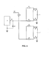
- Figure 3 shows a third embodiment with an operating circuit, which is also designed via two discharge lamps 1 and 1 '.
- the helix interrogation described only takes place for the lower electrode 3 or 3 ', because in use it forms the "cold end" of the lamp 1 or 1'.
- two lamps 1 and 1 'working in parallel can be monitored here in a particularly simple manner with a uniform circuit.
- the EOL early detection takes place via the already explained resistors 4 and 5 or 4 'and 5'. If the DC voltage between the electrodes 2 and 3 or between the electrodes 2 'and 3' becomes too great, this is detected in the same way as in the first exemplary embodiment from FIG. 1.
Landscapes
- Circuit Arrangements For Discharge Lamps (AREA)
- Polyesters Or Polycarbonates (AREA)
Applications Claiming Priority (2)
| Application Number | Priority Date | Filing Date | Title |
|---|---|---|---|
| DE10209620 | 2002-03-05 | ||
| DE10209620A DE10209620A1 (de) | 2002-03-05 | 2002-03-05 | EOL-Erkennung mit integrieter Wendelabfrage |
Publications (3)
| Publication Number | Publication Date |
|---|---|
| EP1343359A2 true EP1343359A2 (fr) | 2003-09-10 |
| EP1343359A3 EP1343359A3 (fr) | 2004-04-21 |
| EP1343359B1 EP1343359B1 (fr) | 2011-06-01 |
Family
ID=27740640
Family Applications (1)
| Application Number | Title | Priority Date | Filing Date |
|---|---|---|---|
| EP03003547A Expired - Lifetime EP1343359B1 (fr) | 2002-03-05 | 2003-02-17 | EOL-détection avec une interrogation d'électrode intégrée |
Country Status (6)
| Country | Link |
|---|---|
| US (1) | US6646390B2 (fr) |
| EP (1) | EP1343359B1 (fr) |
| CN (1) | CN1443030B (fr) |
| AT (1) | ATE511742T1 (fr) |
| CA (1) | CA2420816A1 (fr) |
| DE (1) | DE10209620A1 (fr) |
Cited By (2)
| Publication number | Priority date | Publication date | Assignee | Title |
|---|---|---|---|---|
| DE102010029511A1 (de) | 2010-05-31 | 2011-12-01 | Osram Gesellschaft mit beschränkter Haftung | Schaltungsanordnung zum Betreiben einer Entladungslampe |
| US8754582B2 (en) | 2009-01-16 | 2014-06-17 | Osram Gesellschaft Mit Beschraenkter Haftung | Detector circuit and method for actuating a fluorescent lamp |
Families Citing this family (6)
| Publication number | Priority date | Publication date | Assignee | Title |
|---|---|---|---|---|
| US6854117B1 (en) * | 2000-10-31 | 2005-02-08 | Caspian Networks, Inc. | Parallel network processor array |
| DE10209619A1 (de) * | 2002-03-05 | 2003-09-25 | Patent Treuhand Ges Fuer Elektrische Gluehlampen Mbh | Betriebsschaltung für Entladungslampe mit EOL-Früherkennung |
| US8482213B1 (en) | 2009-06-29 | 2013-07-09 | Panasonic Corporation | Electronic ballast with pulse detection circuit for lamp end of life and output short protection |
| US8947020B1 (en) | 2011-11-17 | 2015-02-03 | Universal Lighting Technologies, Inc. | End of life control for parallel lamp ballast |
| DE102012207002A1 (de) * | 2011-12-23 | 2013-06-27 | Tridonic Gmbh & Co. Kg | Verfahren, Betriebsgerät und Beleuchtungssystem |
| DE102021200762A1 (de) * | 2021-01-28 | 2022-07-28 | BSH Hausgeräte GmbH | Mess-Vorrichtung zur differentiellen Spannungsmessung |
Family Cites Families (6)
| Publication number | Priority date | Publication date | Assignee | Title |
|---|---|---|---|---|
| JPH01166495A (ja) * | 1987-12-23 | 1989-06-30 | Matsushita Electric Works Ltd | 放電灯点灯装置 |
| JP3521602B2 (ja) * | 1996-03-06 | 2004-04-19 | 株式会社デンソー | 放電灯点灯装置 |
| US5808422A (en) * | 1996-05-10 | 1998-09-15 | Philips Electronics North America | Lamp ballast with lamp rectification detection circuitry |
| DE19819027A1 (de) * | 1998-04-29 | 1999-11-04 | Patent Treuhand Ges Fuer Elektrische Gluehlampen Mbh | Schaltungsanordnung zum Betrieb mindestens einer Entladungslampe |
| US6008592A (en) * | 1998-06-10 | 1999-12-28 | International Rectifier Corporation | End of lamp life or false lamp detection circuit for an electronic ballast |
| DE19852350A1 (de) * | 1998-11-13 | 2000-05-18 | Hella Kg Hueck & Co | Diagnosesystem für das Vorschaltgerät einer Hochdruckgasentladungslampe in einem Kraftfahrzeug |
-
2002
- 2002-03-05 DE DE10209620A patent/DE10209620A1/de not_active Withdrawn
-
2003
- 2003-02-17 AT AT03003547T patent/ATE511742T1/de active
- 2003-02-17 EP EP03003547A patent/EP1343359B1/fr not_active Expired - Lifetime
- 2003-03-04 CA CA002420816A patent/CA2420816A1/fr not_active Abandoned
- 2003-03-05 CN CN03110542.4A patent/CN1443030B/zh not_active Expired - Fee Related
- 2003-03-05 US US10/378,895 patent/US6646390B2/en not_active Expired - Lifetime
Cited By (3)
| Publication number | Priority date | Publication date | Assignee | Title |
|---|---|---|---|---|
| US8754582B2 (en) | 2009-01-16 | 2014-06-17 | Osram Gesellschaft Mit Beschraenkter Haftung | Detector circuit and method for actuating a fluorescent lamp |
| DE102010029511A1 (de) | 2010-05-31 | 2011-12-01 | Osram Gesellschaft mit beschränkter Haftung | Schaltungsanordnung zum Betreiben einer Entladungslampe |
| WO2011151107A1 (fr) | 2010-05-31 | 2011-12-08 | Osram Gesellschaft mit beschränkter Haftung | Ensemble circuit de fonctionnement d'une lampe à décharge |
Also Published As
| Publication number | Publication date |
|---|---|
| US20030168995A1 (en) | 2003-09-11 |
| EP1343359A3 (fr) | 2004-04-21 |
| CA2420816A1 (fr) | 2003-09-05 |
| DE10209620A1 (de) | 2003-09-25 |
| CN1443030B (zh) | 2010-04-21 |
| EP1343359B1 (fr) | 2011-06-01 |
| ATE511742T1 (de) | 2011-06-15 |
| US6646390B2 (en) | 2003-11-11 |
| CN1443030A (zh) | 2003-09-17 |
Similar Documents
| Publication | Publication Date | Title |
|---|---|---|
| DE3705222C2 (fr) | ||
| DE4331378C2 (de) | Schaltungsanordnung zum Betrieb einer Hochdruck-Entladungslampe für einen Fahrzeugscheinwerfer | |
| DE3906886A1 (de) | Laststeuereinrichtung | |
| EP0677981B1 (fr) | Ballast, avec dispositif de reconnaissance de changement de lampe, pour tubes à décharge | |
| EP0301442A2 (fr) | Circuit pour la supervision de fils vers un interrupteur ou un détecteur | |
| DE102009028665B4 (de) | System zum Verfahren zur adaptiven Lastfehlerdetektion | |
| DE102004037388B4 (de) | Verfahren zur Detektion eines Nicht-Nullspannungsschaltbetriebs eines Vorschaltgeräts für Leuchtstofflampen und Vorschaltgerät | |
| DE10108138A1 (de) | Schutzschaltung für eine Leuchstofflampe | |
| EP3124988B1 (fr) | Circuit de commande de diodes electroluminescentes pour un emetteur de signal d'une installation de signal lumineux | |
| EP1343359B1 (fr) | EOL-détection avec une interrogation d'électrode intégrée | |
| DE19801132A1 (de) | Stromversorgungsschaltung für eine Entladungslampe mit Leuchtzustandsdetektor | |
| EP0754303A1 (fr) | Systeme de controle fiable de la tension | |
| EP2138015B1 (fr) | Circuit permettant de produire une tension auxiliaire et de faire fonctionner au moins une lampe à décharge | |
| DE2547495A1 (de) | Warnsystem | |
| EP1343360A2 (fr) | Circuit pour alimenter une lampe à décharge muni d'une détection de fin de durée de vie | |
| EP1901591B1 (fr) | Allumage de lampes à décharge dans des conditions environnementales variables | |
| EP0763746A2 (fr) | Circuit de détection d'un circuit ouvert | |
| DE102010031219A1 (de) | Schaltungsanordnung und Verfahren zum Betreiben mindestens einer Entladungslampe | |
| EP1424881A1 (fr) | Dispositif et méthode pour commander une lampe fluorescente | |
| DE10240110A1 (de) | Entladungslampen-Beleuchtungsschaltung | |
| DE19532677B4 (de) | Überwachungsschaltung für wenigstens eine Versorgungsspannung | |
| EP0558772B1 (fr) | Circuit pour le fonctionnement de plusieurs lampes fluorescentes avec un ballast | |
| EP2515617B1 (fr) | Appareil d'entrée électronique destiné au fonctionnement d'au moins une DEL et/ou au moins une lampe à décharge | |
| DE102009004851A1 (de) | Detektorschaltung und Verfahren zur Ansteuerung einer Leuchtstofflampe | |
| DE19505460A1 (de) | Schaltungsanordnung zum Betrieb einer Entladungslampe |
Legal Events
| Date | Code | Title | Description |
|---|---|---|---|
| PUAI | Public reference made under article 153(3) epc to a published international application that has entered the european phase |
Free format text: ORIGINAL CODE: 0009012 |
|
| AK | Designated contracting states |
Kind code of ref document: A2 Designated state(s): AT BE BG CH CY CZ DE DK EE ES FI FR GB GR HU IE IT LI LU MC NL PT SE SI SK TR |
|
| AX | Request for extension of the european patent |
Extension state: AL LT LV MK RO |
|
| PUAL | Search report despatched |
Free format text: ORIGINAL CODE: 0009013 |
|
| AK | Designated contracting states |
Kind code of ref document: A3 Designated state(s): AT BE BG CH CY CZ DE DK EE ES FI FR GB GR HU IE IT LI LU MC NL PT SE SI SK TR |
|
| AX | Request for extension of the european patent |
Extension state: AL LT LV MK RO |
|
| 17P | Request for examination filed |
Effective date: 20040504 |
|
| AKX | Designation fees paid |
Designated state(s): AT BE BG CH CY CZ DE DK EE ES FI FR GB GR HU IE IT LI LU MC NL PT SE SI SK TR |
|
| 17Q | First examination report despatched |
Effective date: 20050315 |
|
| 17Q | First examination report despatched |
Effective date: 20050315 |
|
| GRAP | Despatch of communication of intention to grant a patent |
Free format text: ORIGINAL CODE: EPIDOSNIGR1 |
|
| RAP1 | Party data changed (applicant data changed or rights of an application transferred) |
Owner name: OSRAM GESELLSCHAFT MIT BESCHRAENKTER HAFTUNG |
|
| GRAS | Grant fee paid |
Free format text: ORIGINAL CODE: EPIDOSNIGR3 |
|
| GRAA | (expected) grant |
Free format text: ORIGINAL CODE: 0009210 |
|
| AK | Designated contracting states |
Kind code of ref document: B1 Designated state(s): AT BE BG CH CY CZ DE DK EE ES FI FR GB GR HU IE IT LI LU MC NL PT SE SI SK TR |
|
| REG | Reference to a national code |
Ref country code: GB Ref legal event code: FG4D Free format text: NOT ENGLISH |
|
| REG | Reference to a national code |
Ref country code: CH Ref legal event code: EP |
|
| REG | Reference to a national code |
Ref country code: IE Ref legal event code: FG4D Free format text: LANGUAGE OF EP DOCUMENT: GERMAN |
|
| REG | Reference to a national code |
Ref country code: DE Ref legal event code: R096 Ref document number: 50313724 Country of ref document: DE Effective date: 20110714 |
|
| REG | Reference to a national code |
Ref country code: NL Ref legal event code: VDEP Effective date: 20110601 |
|
| PG25 | Lapsed in a contracting state [announced via postgrant information from national office to epo] |
Ref country code: SE Free format text: LAPSE BECAUSE OF FAILURE TO SUBMIT A TRANSLATION OF THE DESCRIPTION OR TO PAY THE FEE WITHIN THE PRESCRIBED TIME-LIMIT Effective date: 20110601 |
|
| PG25 | Lapsed in a contracting state [announced via postgrant information from national office to epo] |
Ref country code: GR Free format text: LAPSE BECAUSE OF FAILURE TO SUBMIT A TRANSLATION OF THE DESCRIPTION OR TO PAY THE FEE WITHIN THE PRESCRIBED TIME-LIMIT Effective date: 20110902 Ref country code: ES Free format text: LAPSE BECAUSE OF FAILURE TO SUBMIT A TRANSLATION OF THE DESCRIPTION OR TO PAY THE FEE WITHIN THE PRESCRIBED TIME-LIMIT Effective date: 20110912 Ref country code: CY Free format text: LAPSE BECAUSE OF FAILURE TO SUBMIT A TRANSLATION OF THE DESCRIPTION OR TO PAY THE FEE WITHIN THE PRESCRIBED TIME-LIMIT Effective date: 20110601 Ref country code: SI Free format text: LAPSE BECAUSE OF FAILURE TO SUBMIT A TRANSLATION OF THE DESCRIPTION OR TO PAY THE FEE WITHIN THE PRESCRIBED TIME-LIMIT Effective date: 20110601 |
|
| REG | Reference to a national code |
Ref country code: IE Ref legal event code: FD4D |
|
| PG25 | Lapsed in a contracting state [announced via postgrant information from national office to epo] |
Ref country code: NL Free format text: LAPSE BECAUSE OF FAILURE TO SUBMIT A TRANSLATION OF THE DESCRIPTION OR TO PAY THE FEE WITHIN THE PRESCRIBED TIME-LIMIT Effective date: 20110601 |
|
| REG | Reference to a national code |
Ref country code: DE Ref legal event code: R081 Ref document number: 50313724 Country of ref document: DE Owner name: OSRAM GMBH, DE Free format text: FORMER OWNER: PATENT-TREUHAND-GESELLSCHAFT FUER ELEKTRISCHE GLUEHLAMPEN MBH, 81543 MUENCHEN, DE Effective date: 20110505 Ref country code: DE Ref legal event code: R081 Ref document number: 50313724 Country of ref document: DE Owner name: OSRAM GMBH, DE Free format text: FORMER OWNER: OSRAM GESELLSCHAFT MIT BESCHRAENKTER HAFTUNG, 81543 MUENCHEN, DE Effective date: 20111130 |
|
| PG25 | Lapsed in a contracting state [announced via postgrant information from national office to epo] |
Ref country code: EE Free format text: LAPSE BECAUSE OF FAILURE TO SUBMIT A TRANSLATION OF THE DESCRIPTION OR TO PAY THE FEE WITHIN THE PRESCRIBED TIME-LIMIT Effective date: 20110601 Ref country code: CZ Free format text: LAPSE BECAUSE OF FAILURE TO SUBMIT A TRANSLATION OF THE DESCRIPTION OR TO PAY THE FEE WITHIN THE PRESCRIBED TIME-LIMIT Effective date: 20110601 Ref country code: IE Free format text: LAPSE BECAUSE OF FAILURE TO SUBMIT A TRANSLATION OF THE DESCRIPTION OR TO PAY THE FEE WITHIN THE PRESCRIBED TIME-LIMIT Effective date: 20110601 Ref country code: PT Free format text: LAPSE BECAUSE OF FAILURE TO SUBMIT A TRANSLATION OF THE DESCRIPTION OR TO PAY THE FEE WITHIN THE PRESCRIBED TIME-LIMIT Effective date: 20111003 |
|
| PG25 | Lapsed in a contracting state [announced via postgrant information from national office to epo] |
Ref country code: SK Free format text: LAPSE BECAUSE OF FAILURE TO SUBMIT A TRANSLATION OF THE DESCRIPTION OR TO PAY THE FEE WITHIN THE PRESCRIBED TIME-LIMIT Effective date: 20110601 |
|
| PLBE | No opposition filed within time limit |
Free format text: ORIGINAL CODE: 0009261 |
|
| STAA | Information on the status of an ep patent application or granted ep patent |
Free format text: STATUS: NO OPPOSITION FILED WITHIN TIME LIMIT |
|
| 26N | No opposition filed |
Effective date: 20120302 |
|
| PG25 | Lapsed in a contracting state [announced via postgrant information from national office to epo] |
Ref country code: IT Free format text: LAPSE BECAUSE OF FAILURE TO SUBMIT A TRANSLATION OF THE DESCRIPTION OR TO PAY THE FEE WITHIN THE PRESCRIBED TIME-LIMIT Effective date: 20110601 |
|
| REG | Reference to a national code |
Ref country code: DE Ref legal event code: R097 Ref document number: 50313724 Country of ref document: DE Effective date: 20120302 |
|
| PG25 | Lapsed in a contracting state [announced via postgrant information from national office to epo] |
Ref country code: DK Free format text: LAPSE BECAUSE OF FAILURE TO SUBMIT A TRANSLATION OF THE DESCRIPTION OR TO PAY THE FEE WITHIN THE PRESCRIBED TIME-LIMIT Effective date: 20110601 |
|
| BERE | Be: lapsed |
Owner name: OSRAM G.M.B.H. Effective date: 20120228 |
|
| PG25 | Lapsed in a contracting state [announced via postgrant information from national office to epo] |
Ref country code: MC Free format text: LAPSE BECAUSE OF NON-PAYMENT OF DUE FEES Effective date: 20120229 |
|
| REG | Reference to a national code |
Ref country code: CH Ref legal event code: PL |
|
| PG25 | Lapsed in a contracting state [announced via postgrant information from national office to epo] |
Ref country code: CH Free format text: LAPSE BECAUSE OF NON-PAYMENT OF DUE FEES Effective date: 20120229 Ref country code: LI Free format text: LAPSE BECAUSE OF NON-PAYMENT OF DUE FEES Effective date: 20120229 |
|
| PG25 | Lapsed in a contracting state [announced via postgrant information from national office to epo] |
Ref country code: BE Free format text: LAPSE BECAUSE OF NON-PAYMENT OF DUE FEES Effective date: 20120228 |
|
| REG | Reference to a national code |
Ref country code: DE Ref legal event code: R081 Ref document number: 50313724 Country of ref document: DE Owner name: OSRAM GMBH, DE Free format text: FORMER OWNER: OSRAM AG, 81543 MUENCHEN, DE Effective date: 20130205 |
|
| REG | Reference to a national code |
Ref country code: AT Ref legal event code: MM01 Ref document number: 511742 Country of ref document: AT Kind code of ref document: T Effective date: 20120217 |
|
| PG25 | Lapsed in a contracting state [announced via postgrant information from national office to epo] |
Ref country code: AT Free format text: LAPSE BECAUSE OF NON-PAYMENT OF DUE FEES Effective date: 20120217 Ref country code: BG Free format text: LAPSE BECAUSE OF FAILURE TO SUBMIT A TRANSLATION OF THE DESCRIPTION OR TO PAY THE FEE WITHIN THE PRESCRIBED TIME-LIMIT Effective date: 20110901 |
|
| REG | Reference to a national code |
Ref country code: DE Ref legal event code: R081 Ref document number: 50313724 Country of ref document: DE Owner name: OSRAM GMBH, DE Free format text: FORMER OWNER: OSRAM GMBH, 81543 MUENCHEN, DE Effective date: 20130822 |
|
| PG25 | Lapsed in a contracting state [announced via postgrant information from national office to epo] |
Ref country code: TR Free format text: LAPSE BECAUSE OF FAILURE TO SUBMIT A TRANSLATION OF THE DESCRIPTION OR TO PAY THE FEE WITHIN THE PRESCRIBED TIME-LIMIT Effective date: 20110601 |
|
| PG25 | Lapsed in a contracting state [announced via postgrant information from national office to epo] |
Ref country code: LU Free format text: LAPSE BECAUSE OF NON-PAYMENT OF DUE FEES Effective date: 20120217 |
|
| PG25 | Lapsed in a contracting state [announced via postgrant information from national office to epo] |
Ref country code: HU Free format text: LAPSE BECAUSE OF FAILURE TO SUBMIT A TRANSLATION OF THE DESCRIPTION OR TO PAY THE FEE WITHIN THE PRESCRIBED TIME-LIMIT Effective date: 20030217 |
|
| REG | Reference to a national code |
Ref country code: FR Ref legal event code: PLFP Year of fee payment: 14 |
|
| REG | Reference to a national code |
Ref country code: FR Ref legal event code: PLFP Year of fee payment: 15 |
|
| REG | Reference to a national code |
Ref country code: FR Ref legal event code: PLFP Year of fee payment: 16 |
|
| PGFP | Annual fee paid to national office [announced via postgrant information from national office to epo] |
Ref country code: GB Payment date: 20190218 Year of fee payment: 17 Ref country code: FI Payment date: 20190219 Year of fee payment: 17 |
|
| PGFP | Annual fee paid to national office [announced via postgrant information from national office to epo] |
Ref country code: FR Payment date: 20190219 Year of fee payment: 17 |
|
| PGFP | Annual fee paid to national office [announced via postgrant information from national office to epo] |
Ref country code: DE Payment date: 20200219 Year of fee payment: 18 |
|
| REG | Reference to a national code |
Ref country code: FI Ref legal event code: MAE |
|
| GBPC | Gb: european patent ceased through non-payment of renewal fee |
Effective date: 20200217 |
|
| PG25 | Lapsed in a contracting state [announced via postgrant information from national office to epo] |
Ref country code: FI Free format text: LAPSE BECAUSE OF NON-PAYMENT OF DUE FEES Effective date: 20200217 |
|
| PG25 | Lapsed in a contracting state [announced via postgrant information from national office to epo] |
Ref country code: GB Free format text: LAPSE BECAUSE OF NON-PAYMENT OF DUE FEES Effective date: 20200217 Ref country code: FR Free format text: LAPSE BECAUSE OF NON-PAYMENT OF DUE FEES Effective date: 20200229 |
|
| REG | Reference to a national code |
Ref country code: DE Ref legal event code: R119 Ref document number: 50313724 Country of ref document: DE |
|
| PG25 | Lapsed in a contracting state [announced via postgrant information from national office to epo] |
Ref country code: DE Free format text: LAPSE BECAUSE OF NON-PAYMENT OF DUE FEES Effective date: 20210901 |