EP1343580B1 - Systeme ameliore de craquage catalytique fluidise de molecules d'hydrocarbures - Google Patents
Systeme ameliore de craquage catalytique fluidise de molecules d'hydrocarbures Download PDFInfo
- Publication number
- EP1343580B1 EP1343580B1 EP01957140A EP01957140A EP1343580B1 EP 1343580 B1 EP1343580 B1 EP 1343580B1 EP 01957140 A EP01957140 A EP 01957140A EP 01957140 A EP01957140 A EP 01957140A EP 1343580 B1 EP1343580 B1 EP 1343580B1
- Authority
- EP
- European Patent Office
- Prior art keywords
- riser
- catalytic cracking
- fluidized catalytic
- rib
- cracking system
- Prior art date
- Legal status (The legal status is an assumption and is not a legal conclusion. Google has not performed a legal analysis and makes no representation as to the accuracy of the status listed.)
- Expired - Lifetime
Links
Images




Classifications
-
- B—PERFORMING OPERATIONS; TRANSPORTING
- B01—PHYSICAL OR CHEMICAL PROCESSES OR APPARATUS IN GENERAL
- B01J—CHEMICAL OR PHYSICAL PROCESSES, e.g. CATALYSIS OR COLLOID CHEMISTRY; THEIR RELEVANT APPARATUS
- B01J8/00—Chemical or physical processes in general, conducted in the presence of fluids and solid particles; Apparatus for such processes
- B01J8/18—Chemical or physical processes in general, conducted in the presence of fluids and solid particles; Apparatus for such processes with fluidised particles
- B01J8/24—Chemical or physical processes in general, conducted in the presence of fluids and solid particles; Apparatus for such processes with fluidised particles according to "fluidised-bed" technique
- B01J8/38—Chemical or physical processes in general, conducted in the presence of fluids and solid particles; Apparatus for such processes with fluidised particles according to "fluidised-bed" technique with fluidised bed containing a rotatable device or being subject to rotation or to a circulatory movement, i.e. leaving a vessel and subsequently re-entering it
- B01J8/384—Chemical or physical processes in general, conducted in the presence of fluids and solid particles; Apparatus for such processes with fluidised particles according to "fluidised-bed" technique with fluidised bed containing a rotatable device or being subject to rotation or to a circulatory movement, i.e. leaving a vessel and subsequently re-entering it being subject to a circulatory movement only
- B01J8/388—Chemical or physical processes in general, conducted in the presence of fluids and solid particles; Apparatus for such processes with fluidised particles according to "fluidised-bed" technique with fluidised bed containing a rotatable device or being subject to rotation or to a circulatory movement, i.e. leaving a vessel and subsequently re-entering it being subject to a circulatory movement only externally, i.e. the particles leaving the vessel and subsequently re-entering it
-
- B—PERFORMING OPERATIONS; TRANSPORTING
- B01—PHYSICAL OR CHEMICAL PROCESSES OR APPARATUS IN GENERAL
- B01F—MIXING, e.g. DISSOLVING, EMULSIFYING OR DISPERSING
- B01F25/00—Flow mixers; Mixers for falling materials, e.g. solid particles
- B01F25/40—Static mixers
- B01F25/42—Static mixers in which the mixing is affected by moving the components jointly in changing directions, e.g. in tubes provided with baffles or obstructions
- B01F25/43—Mixing tubes, e.g. wherein the material is moved in a radial or partly reversed direction
- B01F25/431—Straight mixing tubes with baffles or obstructions that do not cause substantial pressure drop; Baffles therefor
- B01F25/4317—Profiled elements, e.g. profiled blades, bars, pillars, columns or chevrons
-
- B—PERFORMING OPERATIONS; TRANSPORTING
- B01—PHYSICAL OR CHEMICAL PROCESSES OR APPARATUS IN GENERAL
- B01J—CHEMICAL OR PHYSICAL PROCESSES, e.g. CATALYSIS OR COLLOID CHEMISTRY; THEIR RELEVANT APPARATUS
- B01J8/00—Chemical or physical processes in general, conducted in the presence of fluids and solid particles; Apparatus for such processes
- B01J8/18—Chemical or physical processes in general, conducted in the presence of fluids and solid particles; Apparatus for such processes with fluidised particles
- B01J8/1818—Feeding of the fluidising gas
- B01J8/1827—Feeding of the fluidising gas the fluidising gas being a reactant
-
- B—PERFORMING OPERATIONS; TRANSPORTING
- B01—PHYSICAL OR CHEMICAL PROCESSES OR APPARATUS IN GENERAL
- B01J—CHEMICAL OR PHYSICAL PROCESSES, e.g. CATALYSIS OR COLLOID CHEMISTRY; THEIR RELEVANT APPARATUS
- B01J8/00—Chemical or physical processes in general, conducted in the presence of fluids and solid particles; Apparatus for such processes
- B01J8/18—Chemical or physical processes in general, conducted in the presence of fluids and solid particles; Apparatus for such processes with fluidised particles
- B01J8/24—Chemical or physical processes in general, conducted in the presence of fluids and solid particles; Apparatus for such processes with fluidised particles according to "fluidised-bed" technique
- B01J8/26—Chemical or physical processes in general, conducted in the presence of fluids and solid particles; Apparatus for such processes with fluidised particles according to "fluidised-bed" technique with two or more fluidised beds, e.g. reactor and regeneration installations
-
- C—CHEMISTRY; METALLURGY
- C10—PETROLEUM, GAS OR COKE INDUSTRIES; TECHNICAL GASES CONTAINING CARBON MONOXIDE; FUELS; LUBRICANTS; PEAT
- C10G—CRACKING HYDROCARBON OILS; PRODUCTION OF LIQUID HYDROCARBON MIXTURES, e.g. BY DESTRUCTIVE HYDROGENATION, OLIGOMERISATION, POLYMERISATION; RECOVERY OF HYDROCARBON OILS FROM OIL-SHALE, OIL-SAND, OR GASES; REFINING MIXTURES MAINLY CONSISTING OF HYDROCARBONS; REFORMING OF NAPHTHA; MINERAL WAXES
- C10G11/00—Catalytic cracking, in the absence of hydrogen, of hydrocarbon oils
- C10G11/14—Catalytic cracking, in the absence of hydrogen, of hydrocarbon oils with preheated moving solid catalysts
- C10G11/18—Catalytic cracking, in the absence of hydrogen, of hydrocarbon oils with preheated moving solid catalysts according to the "fluidised-bed" technique
-
- B—PERFORMING OPERATIONS; TRANSPORTING
- B01—PHYSICAL OR CHEMICAL PROCESSES OR APPARATUS IN GENERAL
- B01F—MIXING, e.g. DISSOLVING, EMULSIFYING OR DISPERSING
- B01F23/00—Mixing according to the phases to be mixed, e.g. dispersing or emulsifying
- B01F23/50—Mixing liquids with solids
-
- B—PERFORMING OPERATIONS; TRANSPORTING
- B01—PHYSICAL OR CHEMICAL PROCESSES OR APPARATUS IN GENERAL
- B01J—CHEMICAL OR PHYSICAL PROCESSES, e.g. CATALYSIS OR COLLOID CHEMISTRY; THEIR RELEVANT APPARATUS
- B01J2208/00—Processes carried out in the presence of solid particles; Reactors therefor
- B01J2208/00743—Feeding or discharging of solids
- B01J2208/00752—Feeding
Definitions
- the invention relates generally to a system for cracking hydrocarbon molecules. More particularly, the invention provides a fluidized catalytic cracking system having a riser equipped with contoured ribs.
- the contoured ribs enhance mixing of the catalyst and the hydrocarbon feedstock that flow through the riser.
- the FCC process is utilized to crack hydrocarbon materials such as oil. Cracking refers to the conversion of petroleum fractions having a high boiling point into products having a lower boiling point.
- the cracking process is usually performed in a vertically-oriented conduit, or riser, that forms part of an FCC system.
- hot catalyst particles in an aerated (fluidized) state are introduced into a bottom portion of the riser, and are induced to flow upward.
- a hydrocarbon feedstock is injected into the catalyst flow as the catalyst travels through the riser.
- the hydrocarbon feedstock in general, is significantly cooler than the catalyst and rapidly vaporizes upon contact with the catalyst.
- Optimal cracking conditions in an FCC process require a substantially immediate and homogenous mixing of the catalyst and the hydrocarbon feedstock. Such mixing is difficult to achieve, however, and stratified regions of hot catalyst and cold hydrocarbon feedstock typically appear within the catalyst-hydrocarbon flow. Over-cracking and thermal cracking of the hydrocarbon molecules typically occur in the catalyst-rich areas of the flow. Conversely, incomplete cracking of the hydrocarbon molecules usually occurs in hydrocarbon-rich flow regions. These factors can substantially reduce the overall yield of the FCC process.
- Radial-feed-injection of hydrocarbon feedstock is a commonly-used technique for improving the mixing of catalyst and hydrocarbon feedstock in FCC systems.
- This technique involves the use of radial-feed atomizing nozzles positioned around the circumference of the riser. Steam is typically directed to the nozzles to assist in the atomization of the hydrocarbon feedstock.
- Radial-feed nozzles in general, produce a more uniform spray pattern of hydrocarbon feedstock than other injection techniques.
- Common radial-feed nozzles form a flat, fan-shape spray jet that diverges at an angle within the range of approximately 40 to 65 degrees after leaving the atomizing nozzle (this angle is known as the "spray angle" of the nozzle). Spray angles above approximately 65 degrees increase the potential for the erosive spray jet to impinge on the inner surface of the riser.
- FIG. 8 is a cross-sectional view of a common riser 200 having an inner surface 200a.
- a plurality of radial-feed atomizing nozzles 202 are positioned around the circumference of the inner surface 202a.
- the nozzles each produce an individual spray jet 204a of hydrocarbon feedstock.
- the spray jets 204a collectively form a spray pattern 204 within the riser 200.
- a plurality of gaps 204b appear in the spray pattern 204, as shown in Figure 3.
- the gaps 204b are a result of the fan-shaped profiles of the jets 204a, and the plug-flow nature of the catalyst as it travels upward through the spray region of the riser 200.
- the combined area of the gaps 204b can be as large as fifty percent or more of the cross-sectional area of the riser 200.
- the unmixed region of catalyst downstream of the gaps 204b can persist for twenty-five feet or more in the riser of a typical FCC system.
- European Pat. No. 0 960 929 discloses the provision of annular obstacles close to the feed injection paint for deviating catalyst particles into the direction of the central axis.
- An object of the present invention is to provide a fluidized catalytic cracking (FCC) system that effectively mixes a flow of catalyst and hydrocarbon feedstock.
- FCC fluidized catalytic cracking
- a presently-preferred embodiment of the invention provides an FCC system comprising a riser.
- the riser has an outer surface and an inner surface.
- the inner surface defines a central passage that extends substantially along a longitudinal axis of the riser.
- the central passage is used to transport a hydrocarbon feedstock and a catalytic material.
- the fluidized catalytic cracking system further comprises a plurality of atomizing nozzles coupled to the riser, the atomizing nozzles being adapted to inject the hydrocarbon feedstock into a flow of the catalytic material within the central passage so that the atomizing nozzles form a spray pattern of the hydrocarbon feedstock within the central passage.
- the riser inner surface has a plurality of elongated ribs disposed thereon for mixing the hydrocarbon feedstock and the catalytic material.
- the ribs are located between adjacent atomizing nozzles.
- the ribs have an inner wall that faces the central passage and have a thickness defined by a distance between the inner wall and the outer surface of the riser. The thickness varies along at least a portion of a length of the ribs.
- a preferred embodiment of an FCC system comprises a riser having an outer surface and an inner surface.
- the inner surface defines a central passage extending substantially along a longitudinal axis of the riser.
- the FCC system also includes a plurality of atomizing nozzles coupled to the riser.
- the atomizing nozzles are adapted to inject a hydrocarbon feedstock into a flow of catalytic material within the central passage.
- the atomizing nozzles thereby form a spray pattern of the hydrocarbon feedstock within the central passage.
- the FCC system further comprises a plurality of elongated ribs disposed along the riser inner surface.
- a preferred embodiment of an FCC system comprises a riser having an outer surface and an inner surface.
- the inner surface defines a central passage extending substantially along a longitudinal axis of the riser.
- the central passage is used to transport a hydrocarbon feedstock and a catalytic material.
- the FCC system further comprises an elongated rib disposed along the riser inner surface.
- the rib is used to mix the hydrocarbon feedstock and the catalytic material.
- the rib is contoured so that a radial distance between the rib and the longitudinal axis of the riser varies along at least a portion of a length of the rib.
- FIG. 1 A presently-preferred embodiment of the invention is shown in Figures 1 through 4B.
- the figures are each referenced to a common coordinate system 8 denoted in each illustration.
- the invention provides a fluidized catalytic cracking (FCC) system 10.
- the FCC system 10 includes a reactor 12, a regenerator 14, and a riser 16 (see Figure 1).
- the riser 16 is an elongated conduit comprising a metallic out-wall 11 and a liner 13.
- the out-wall 11 has an outer circumferential surface 11a and an inner circumferential surface 11b.
- the liner 13 has an outer circumferential surface 13a and an inner circumferential surface 13b.
- the liner 13 is disposed within the out-wall 11. More particularly, the outer circumferential surface 13a of the liner 13 is anchored to the inner circumferential surface 11b of the out-wall 11.
- the liner 13 is preferably formed from a refractory material.
- the refractory material may be any material that suitably protects the out-wall 11 from the erosive and thermal effects of the flow within the riser 16 (discussed below). Such refractory materials are commonly known to those skilled in the art of fluidized catalytic cracking of hydrocarbons. Further details concerning the liner 13 are presented below.
- the inner circumferential surface 13b of the liner 13 defines a central passage 17.
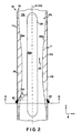
- the central passage 17 extends substantially along a longitudinal centerline C1 of the riser 16 (see Figures 1 and 2).
- the central passage 17 includes a lift zone 17a located proximate the bottom of the riser 16.
- the central passage 17 also includes a feed-injection zone 17b that adjoins the lift zone 17a, and a reaction zone 17c that adjoins the feed-injection zone 17b.
- Hot regenerated catalyst is introduced into the lift zone 17a.
- the catalyst is routed to the lift zone 17a via a standpipe 18.
- the flow-rate of the catalyst is controlled by a valve 20.
- a gaseous fluid such as steam or methane-rich light hydrocarbon gas is routed to the lift zone 17a via a line 22.
- the gaseous fluid is introduced into the lift zone 17a by a distributor 24 located proximate the bottom of the lift zone 17a.
- the gaseous fluid propels (drags) the catalyst particles upward within the central passage 17, i.e., the gaseous fluid induces the catalyst to flow primarily in the direction indicated by an arrow 45 in Figures 1 and 2.
- the FCC system 10 includes eight atomizing nozzles 25.
- the atomizing nozzles 25 are radial-feed nozzles of the type commonly known to those skilled in the art of fluidized catalytic cracking.
- the atomizing nozzles 25 mounted on the riser 16. More particularly, the atomizing nozzles 25 are circumferentially spaced within a common horizontal plane, and are mounted on the riser 16 so that a tip of each nozzle 25 is substantially flush with the inner circumferential surface 13b of the liner 13 (see Figures 2 and 3).
- the number and type of atomizing nozzles 25 in the exemplary embodiment are specified for illustrative purposes only; the invention can be used in conjunction with embodiments that utilize different types and quantities of the atomizing nozzles 25.
- the atomizing nozzles 25 can be arranged in two or more vertically-disposed planes.
- the atomizing nozzles 25 inject hydrocarbon feedstock into the feed-injection zone 17b.
- the atomizing nozzles 25 discharge the hydrocarbon feedstock in the direction denoted by the arrow 54 in Figure 2.
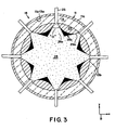
- Each nozzle 25 produces a fan-shaped jet 26a, as shown in Figure 3.
- Each jet 26a forms a spray angle denoted by the symbol " ⁇ " in Figure 3.
- the spray angle ⁇ is preferably within the range of approximately forty to sixty-five degrees in the exemplary embodiment.
- the nozzles 25 preferably inject the hydrocarbon feedstock at an angle within the range of approximately thirty to sixty degrees in relation to the horizontal, i.e., in relation to the x-y plane. This angle is denoted by the symbol " ⁇ " in Figure 2.
- angles ⁇ and ⁇ are presented for exemplary purposes only; the invention can be used in conjunction with atomizing nozzles 25 that produce substantially different values for ⁇ and ⁇ .
- nozzles 25 that produce spray patterns having an ⁇ value as low as minus sixty (-60) degrees may also be utilized, i.e., the nozzles 25 can be pointed downward at an angle as great as sixty degrees in relation to the horizontal.
- the individual jets 26a collectively form a spray pattern 26 of hydrocarbon feedstock within the central passage 17 (see Figure 3).
- the spray pattern 26 is substantially continuous (on a time-averaged basis) proximate the center of the passage 17.
- the spray pattern 26 is broken, i.e., non-continuous, proximate the inner circumferential surface 13b of the liner 13.
- the fan-shaped profile of the jets 26a produces a series of gaps 26b between the spray pattern 26 and the inner circumferential surface 13b, as shown in Figure 3.
- the gaps 26b extend radially inward from the inner circumferential surface 13b, toward the center of the passage 17.
- the fan-shaped geometry of the jets 26a causes the gaps 26b to progressively narrow as the gaps 26b extend inward. Each gap 26b extends inward until reaching a point where the jets 26a of adjacent nozzles 25 converge.
- a plurality of mixing ribs 29 are formed along the inner circumferential surface 13b of the liner 13, proximate the atomizing nozzles 25 (see Figures 1 through 3).
- the number of mixing ribs 29 preferably equals the number of atomizing nozzles 25.
- the exemplary embodiment preferably includes a total of eight mixing ribs 29.
- the ribs 29 promote mixing of the regenerated catalyst and the hydrocarbon feedstock within the feed-injection zone 17b.
- An in-depth description of the structure and function of the mixing ribs 29 is presented below. (For clarity, several of the ribs 29 that would otherwise be visible in the cross-sectional view of Figure 2 are not shown. All of the ribs 29 utilized in the riser 16 are depicted in Figure 3.)
- the mixing of the regenerated catalyst and the hydrocarbon feedstock in the feed-injection zone 17b produces a fluidized bed of catalyst particles and hydrocarbon molecules.
- the fluidized bed flows into the reaction zone 17c upon exiting the feed-injection zone 17b.
- the catalytic particles are contacted with the hydrocarbon molecules primarily in the reaction zone 17c. This contacting gives rise to a chemical reaction that cracks the hydrocarbon molecules.
- the total residence time of the hydrocarbon molecules in the riser 16 is preferably within the range of approximately 1.0 to 3.0 seconds. More preferably, the residence time is within the range of approximately 1.5 to 2.2 seconds. Most preferably, the residence time is within the range of approximately 1.75 to 2.0 seconds.
- This residence time provides the hydrocarbons with a superficial velocity within the range of approximately forty to seventy feet per second (superficial velocity represents the quotient of the volumetric flow rate of the hydrocarbon molecules and the cross-sectional area of the passage 17).
- the fluidized bed of catalyst and hydrocarbon molecules is discharged from the riser 16 into the reactor 12.
- the reactor 12 includes a ballistic separator 30 (see Figure 1).
- the ballistic separator 30 separates the gaseous effluents in the fluidized bed from the deactivated, coke-impregnated catalyst particles.
- the reactor 12 also includes a cyclonic separator 32 located proximate the top of the reactor 12.
- the cyclonic separator 32 further separates the catalyst particles from the hydrocarbon products.
- the gaseous effluents produced by the separation process (including the cracked hydrocarbon molecules) flow out of the reactor 12 via a line 34 located at the top of the cyclonic separator 32. (Alternatively, the gaseous effluents and the catalyst particles may be separated by cyclonic inertial separation at the top of the riser 16.)
- the catalyst particles separated in the above-noted manner drop to a lower portion 12a of the reactor 12 (the portion 12a is commonly referred to as a "catalyst stripper'').
- a stripping gas e.g., steam
- the stripping gas further separates residual hydrocarbon material from the catalyst particles.
- the catalyst particles subsequently flow to the regenerator 14 via a line 38, as indicated by the arrow 39 shown in Figure 1.
- the flow rate of the catalyst particles is controlled by a valve 40 within the line 38.
- the regenerator 14 includes a regeneration chamber 41.
- An oxidizing gas e.g., air
- the oxidizing gas is introduced into the chamber 41 via an air-distributor 44.
- the deactivated, coke-impregnated catalyst particles are simultaneously introduced into the chamber 41 via the line 38.
- the catalyst particles and the oxidizing gas form a fluidized bed 42.
- the catalytic particles are regenerated by combusting the coke within the fluidized bed. Combustion of the coke and any entrained hydrocarbon material still present on or within the catalyst particles restores the catalyst activity.
- Catalyst particles entrained with the resulting combustion-product gases are subsequently separated by a cyclonic separator 48 and returned to the fluidized bed.
- the combustion gases exit the regeneration chamber 41 via a line 50.
- the regenerated catalyst which has been heated by the combustion process, exits the regeneration chamber 41 and is routed to the riser 16 via the standpipe 18 (see the arrow 52 in Figure 1).
- FIG. 4A and 4B Structural details of a preferred embodiment of the mixing ribs 29 are as follows.
- the mixing ribs 29 are most clearly shown in Figures 4A and 4B.
- Each rib 29 has an inner wall 29a that faces the passage 17. This arrangement is most clearly shown in Figure 2.
- the ribs 29 of the exemplary embodiment are oriented so that a longitudinal axis C2 of each rib 29 is substantially parallel to the axis C1 of the riser 16 (see Figure 2).
- each rib 29 has a preferred profile shown most clearly in Figures 2 and 4A.
- the inner wall 29a is contoured in a manner that causes a portion of the catalyst flow within the central passage 17 to flow inward, toward the centerline C1.
- the inner walls 29a give the central passage 17 the cross-sectional profile shown in Figure 2. This feature enhances the mixing of the hydrocarbon feedstock and the catalyst within the central passage 17, as explained in detail below.
- Diametrically-opposed ribs 29 are depicted in the figures for illustrative purposes only; embodiments in which the ribs 29 are not arranged in this manner are also within the contemplated scope of the invention.
- the inner wall 29a has a first inclined portion 29c and an adjoining first concave portion 29d (the various slopes and contours of the inner wall 29a have been exaggerated in Figure 4A for clarity).
- the inner wall 29a also includes a convex portion 29e that adjoins the first concave portion 29d, and a second concave portion 29f that adjoins the convex portion 29e.
- the inner wall 29a further includes a second inclined portion 29g that adjoins the second concave portion 29f.
- the first inclined portion 29c has a substantially straight longitudinal cross-section, as is shown most clearly in Figure 4A.
- the longitudinal cross-section of the portion 29c forms an oblique angle in relation to the the outer circumferential surface 13a of the liner 13. This angle is denoted by the symbol " ⁇ " in Figure 4A.
- the angled orientation of the inclined portion 29c causes the inner wall 29a to extend inward, toward the axis C1, in relation to the oncoming catalyst flow within the central passage 17.
- the concave portion 29d causes the inner wall 29a to extend further inward in relation to the oncoming catalyst flow. More specifically, the curvilinear profile of the concave portion 29d gradually increases the rate at which the portion 29d extends inward along the direction of flow.
- the convex profile of the convex portion 29e causes the rate at which the inner wall 29a extends inward to gradually decrease along the direction of catalyst flow.
- the convex profile of the portion 29e causes the portion 29e to begin extending away from the axis C1 as the convex portion 29e continues to extend in the direction of flow (see Figure 4A).
- the second inclined portion 29g has a substantially straight longitudinal cross-section (see Figure 4A).
- the longitudinal cross-section of the portion 29g forms an oblique angle in relation to the outer circumferential surface 13a of the liner 13. This angle is denoted by the symbol " ⁇ " in Figure 4A.
- the profiles of the second inclined portion 29g and the second concave portion 29f cause the inner wall 29a to continue to extend away from the axis C 1 in relation to the oncoming flow.
- the second concave portion 29f preferably has a radius (or radii) of curvature greater than the radius (or radii) of curvature of the first concave portion 29d, as is most clearly shown in Figure 4A.
- This feature causes the distance between the second concave portion 29f and the outer circumferential surface 13a of the liner 13 to change at a more gradual rate than the distance between the first concave portion 29d and the outer circumferential surface 13a. The significance of this feature is explained below.
- the inner wall 29a preferably has a substantially arcuate transverse cross-section as shown in Figure 3.
- the ribs 29 are positioned so that a portion of each rib 29 is disposed between adjacent atomizing nozzles 25 (see Figures 2 and 3).
- each rib 29 is positioned so that the first concave portion 29d of the rib 29 is located proximate the point at which the adjacent atomizing nozzles 25 discharge into the central passage 17.
- the functional significance of this feature is discussed below.
- the mixing ribs 29 direct the flow of catalyst inward within the central passage 17. This action improves mixing between the catalyst and the hydrocarbon feedstock, as noted previously. More particularly, the ribs 29 direct the catalyst flow away from the spray-pattern gaps 26b and into the spray pattern 26. Hence, the ribs 29 cause a substantial entirety of the catalyst flow to be brought into contact with the hydrocarbon feedstock within the feed-injection zone 17b of the central passage 17.
- the ribs 29 perform the above-noted mixing function as a result of the geometry of the rib inner walls 29a, and the relative positions of the ribs 29 and the atomizing nozzles 25. Specifically, the ribs 29 are located between adjacent atomizing nozzles 25, as previously described. Hence, the ribs 29 are radially aligned with the gaps 26b in the hydrocarbon spray pattern 26 (see Figure 3). The contoured profile of the ribs 29 thus forces the catalyst within the gaps 26b inward, toward the spray pattern 26, as the catalyst flows through the feed-injection zone 17b. In other words, the rib inner walls 29a impart a radial velocity to the catalyst flow located within the spray-pattern gaps 26b.
- the radial velocity component urges the catalyst into the hydrocarbon spray pattern 26. This action causes a forced mixing of the catalyst and the hydrocarbon feedstock within the feed-injection zone 17a. Furthermore, the ribs 29 are vertically positioned so that the catalyst flow from the gaps 26b is directed into the hydrocarbon feedstock at about the point where the jets 26a have fully developed. This feature further enhances the mixing of the catalyst and hydrocarbon streams.
- the inward extension of the portions 29c, 29d, and 29e of the inner wall 29a causes the cross-sectional area of the central passage 17 to decrease.
- This decrease causes a corresponding increase in the velocity of the flow within the feed-injection zone 17b.
- the velocity increase further enhances mixing of the catalyst and the hydrocarbon feedstock. Specifically, the velocity increase raises the level of turbulence in the catalyst-hydrocarbon flow, and thereby enhances mixing within the flow.
- the decreased cross-sectional area of the passage 17 reduces the horizontal (x and y-axis) distance that the hydrocarbon feedstock must travel in order to radially mix with the catalyst.
- the geometric profile of the rib inner wall 29a inhibits flow separation from the inner wall 29a.
- the presence of the inclined portions 29c and 29g and the relatively shallow taper of the concave portion 29f reduces the tendency for the flow to separate from the inner wall 29a.
- Flow separation has the undesirable effect of increasing the pressure drop in the flow within the passage 17; flow separation also increases erosion of the inner walls 29a of the ribs 29.
- the transverse cross-sectional profile of the ribs 29 further inhibits erosion of the inner walls 29a of the ribs 29.
- the rib inner walls 29a are shaped so as to prevent the jets 26a from impinging directly on the ribs 29. This feature is most clearly shown in Figure 3.
- the substantially arcuate cross-section of the inner wall 29a causes the inner walls 29a to remain within the spray-pattern gaps 26b. Hence, the erosive effects caused by direct impingement of the jets 26a on the rib walls 29a are avoided.
- the present invention provides numerous advantages in relation to common FCC systems.
- the enhanced mixing provided by the ribs 29 substantially improves the overall yield of the FCC process.
- the improved contacting of the catalyst and the hydrocarbon feedstock alleviates the over-cracking and thermal cracking that typically occur in catalyst-rich areas of the catalyst-hydrocarbon flow.
- the improved contacting alleviates the incomplete vaporization of the hydrocarbon feedstock that is characteristic of hydrocarbon-rich flow regions.
- the undesirable side-effects of incomplete mixing e.g., deactivation of the catalyst within the riser 16 due to coke laydown, regeneration of the catalyst within the regenerator 14 due to the combustion of air and residual coke, and the production of excessive amounts of lower-boiling-range gaseous reaction products, are substantially reduced by the use of the mixing ribs 29.
- the mixing ribs 29 contain no moving parts, and can be added to existing FCC systems at a relatively modest expense. Furthermore, the mixing ribs 29 function without the use of any support equipment, e.g., compressed-air or hydraulic systems. Also, the use of the ribs 29 requires no substantial expenditures of labor or money after the ribs 29 have been installed in the riser 16. Additionally, the ribs 29 produce minimal pressure losses in the catalyst-hydrocarbon flow, and are subject to minimal amounts of erosion due to the above-described characteristics of the inner wall 29a.
- the riser 16 of the exemplary FCC system 10 is substantially straight, i.e., a substantial entirety of the riser 16 is vertically-oriented.
- FCC systems within the contemplated scope of the invention may comprise risers having portions that are not vertically-oriented (the ribs 29 would preferably be located in a lower, vertically-oriented portion of such risers).
- the ribs 29 may be formed separately from the liner 13, i.e., the ribs 29 do not necessarily have to be formed as an integral part of the liner 13 as in the exemplary embodiment.
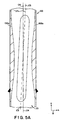
- Figure 5A illustrates another possible variation within the contemplated scope of the invention.
- Figure 5A shows a riser 100.
- the riser 100 defines a central passage 101.
- a plurality of mixing ribs 102a are disposed on an inner surface 100a of the riser 100.
- the mixing ribs 102a are positioned so that a longitudinal axis C3 of each rib 102a is oriented at an oblique angle ⁇ in relation to a longitudinal axis C4 of the riser 100 (the riser 100, the central passage 101, and the mixing ribs 102a are otherwise substantially identical to the riser 16, the central passage 17, and the mixing ribs 29, respectively).
- the angled orientation of the ribs 102 induces a swirling motion in the flow within the central passage 101.
- This swirling motion potentially increases the amount of catalyst flow that is urged inward, toward the center of the passage 101.
- the swirling motion tends to induce unmixed catalyst away from the inner surface 100a, and toward the hydrocarbon-rich center of the passage 101.
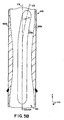
- ribs 102b may be used in place of the ribs 102a, as shown in Figure 5B.
- the ribs 102b are angled in relation to the longitudinal axis C4 of the riser 100 at their upper ends only. In other words, the lower portions of the ribs 102b extend substantially parallel to the longitudinal axis C4, while the upper portions of the ribs 102b extend at the oblique angle ⁇ in relation to the axis C4.
- Figures 6 and 7 illustrate a further variation within the contemplated scope of the invention.
- Figures 6 and 7 depict a riser 110.
- the riser 110 defies a central passage 111.
- Regenerated catalyst enters the central passage 111 by way of a line 114, as indicated by the arrow 116.
- the riser 110 includes a plurality of axial-feed atomizing nozzles 112 positioned within the central passage 111.
- a plurality of mixing ribs 113 are disposed on an inner surface 110a of the riser 110 (the riser 110 and the central passage 111 are otherwise substantially identical to the riser 16 and the central passage 17, respectively, of the exemplary embodiment).
- Axial-feed nozzles such as the nozzles 112 are commonly mounted on wye-shaped riser bases (not shown). The nozzles 112 and the corresponding bases are positioned entirely within the central passage 111.
- the noted mounting arrangement for the nozzles 112 inhibits complete mixing of the catalyst and the hydrocarbon feedstock within the central passage 111.
- the flow of the catalyst over the nozzles 112 and the corresponding nozzle bases discourages catalyst-hydrocarbon mixing directly downstream of the nozzles 112.
- This disadvantage can be reduced by the use of the mixing ribs 113.
- the mixing ribs 113 can be utilized to force a portion of the catalyst flow into the areas directly downstream of the nozzles 112.
Landscapes
- Chemical & Material Sciences (AREA)
- Chemical Kinetics & Catalysis (AREA)
- Engineering & Computer Science (AREA)
- Organic Chemistry (AREA)
- Combustion & Propulsion (AREA)
- Oil, Petroleum & Natural Gas (AREA)
- General Chemical & Material Sciences (AREA)
- Dispersion Chemistry (AREA)
- Production Of Liquid Hydrocarbon Mixture For Refining Petroleum (AREA)
- Catalysts (AREA)
- Devices And Processes Conducted In The Presence Of Fluids And Solid Particles (AREA)
Claims (15)
- Système de craquage catalytique fluidisé, comprenant une colonne montante dotée d'une surface extérieure et d'une surface intérieure, la surface intérieure définissant un passage central qui s'étend essentiellement le long d'un axe longitudinal de la colonne montante pour transporter une charge d'alimentation d'hydrocarbure et un matériau catalytique,le système de craquage catalytique fluidisé comprenant en outre une pluralité de tuyères d'atomisation couplées à la colonne montante, les tuyères d'atomisation étant conçues pour injecter la charge d'alimentation d'hydrocarbure dans un courant du matériau catalytique à l'intérieur du passage central de façon que les tuyères d'atomisation forment une forme de jet de la charge d'alimentation d'hydrocarbure à l'intérieur du passage central,la surface intérieure de la colonne montante possédant une pluralité de nervures allongées disposées dessus, servant à mélanger la charge d'alimentation d'hydrocarbure et le matériau catalytique, les nervures étant situées entre des tuyères d'atomisation adjacentes,les nervures comportant une paroi intérieure faisant face au passage central et ayant une épaisseur définie par une distance entre la paroi intérieure et la surface extérieure de la colonne montante, l'épaisseur variant le long d'au moins une partie de la longueur des nervures.
- Système de craquage catalytique fluidisé selon la revendication 1, dans lequel chacune des nervures allongées comprend une paroi intérieure faisant face au passage central, une première partie de la paroi intérieure étant incurvée vers l'intérieur en se dirigeant vers l'axe longitudinal de la colonne montante de telle sorte qu'une partie du courant de matériau catalytique se dirige vers l'axe longitudinal.
- Système de craquage catalytique fluidisé selon la revendication 2, dans lequel une deuxième partie de la paroi intérieure de la nervure est incurvée vers l'extérieur en s'éloignant de l'axe longitudinal de la colonne montante.
- Système de craquage catalytique fluidisé selon la revendication 1, dans lequel la paroi intérieure de la nervure forme une partie de la surface intérieure de la colonne montante.
- Système de craquage catalytique fluidisé selon l'une quelconque des revendications précédentes, dans lequel au moins une partie de la nervure est située à l'intérieur d'un espace dans la forme de jet.
- Système de craquage catalytique fluidisé selon l'une quelconque des revendications précédentes, dans lequel l'épaisseur d'une première partie de la nervure augmente le long d'une direction d'écoulement à l'intérieur du passage central.
- Système de craquage catalytique fluidisé selon l'une quelconque des revendications précédentes, dans lequel l'épaisseur d'une deuxième partie de la nervure diminue le long d'une direction d'écoulement à l'intérieur du passage central.
- Système de craquage catalytique fluidisé selon l'une quelconque des revendications précédentes, dans lequel la première partie de la paroi intérieure de la nervure est située en amont de la deuxième partie.
- Système de craquage catalytique fluidisé selon l'une quelconque des revendications précédentes, dans lequel un axe longitudinal de chaque nervure est essentiellement parallèle à l'axe longitudinal de la colonne montante.
- Système de craquage catalytique fluidisé selon l'une quelconque des revendications 1-8, dans lequel au moins une partie d'un axe longitudinal de chaque nervure est oblique par rapport à l'axe longitudinal de la colonne montante.
- Système de craquage catalytique fluidisé selon l'une quelconque des revendications 1-8, dans lequel une section droite transversale de la paroi intérieure de la nervure a un profil de forme essentiellement arquée.
- Système de craquage catalytique fluidisé selon la revendication 8, dans lequel la première partie de la nervure est reliée à la deuxième partie.
- Système de craquage catalytique fluidisé selon l'une quelconque des revendications 1-12, dans lequel les tuyères d'atomisation sont des tuyères à alimentation radiale ou des tuyères à alimentation axiale.
- Système de craquage catalytique fluidisé selon l'une quelconque des revendications précédentes, dans lequel la paroi intérieure de la nervure comprend une première partie inclinée, une première partie concave reliée à la première partie inclinée, et une partie convexe reliée à la première partie concave.
- Système de craquage catalytique fluidisé selon l'une quelconque des revendications précédentes, dans lequel la paroi intérieure de la nervure comprend en outre une deuxième partie concave reliée à la partie convexe, et une deuxième partie inclinée reliée à la deuxième partie concave.
Applications Claiming Priority (3)
| Application Number | Priority Date | Filing Date | Title |
|---|---|---|---|
| US616448 | 1996-03-15 | ||
| US09/616,448 US6613290B1 (en) | 2000-07-14 | 2000-07-14 | System for fluidized catalytic cracking of hydrocarbon molecules |
| PCT/US2001/022024 WO2002005941A1 (fr) | 2000-07-14 | 2001-07-13 | Systeme ameliore de craquage catalytique fluidise de molecules d'hydrocarbures |
Publications (3)
| Publication Number | Publication Date |
|---|---|
| EP1343580A1 EP1343580A1 (fr) | 2003-09-17 |
| EP1343580A4 EP1343580A4 (fr) | 2006-02-01 |
| EP1343580B1 true EP1343580B1 (fr) | 2007-10-10 |
Family
ID=24469508
Family Applications (1)
| Application Number | Title | Priority Date | Filing Date |
|---|---|---|---|
| EP01957140A Expired - Lifetime EP1343580B1 (fr) | 2000-07-14 | 2001-07-13 | Systeme ameliore de craquage catalytique fluidise de molecules d'hydrocarbures |
Country Status (11)
| Country | Link |
|---|---|
| US (1) | US6613290B1 (fr) |
| EP (1) | EP1343580B1 (fr) |
| JP (1) | JP2004503672A (fr) |
| CN (1) | CN1226078C (fr) |
| AT (1) | ATE375202T1 (fr) |
| AU (2) | AU7891001A (fr) |
| CA (1) | CA2416106C (fr) |
| DE (1) | DE60130918T2 (fr) |
| ES (1) | ES2294017T3 (fr) |
| TW (1) | TWI228057B (fr) |
| WO (1) | WO2002005941A1 (fr) |
Families Citing this family (16)
| Publication number | Priority date | Publication date | Assignee | Title |
|---|---|---|---|---|
| US7594993B2 (en) * | 2003-11-05 | 2009-09-29 | Exxonmobile Research And Engineering Company | FCC feed injection zone |
| US7619127B2 (en) * | 2003-12-23 | 2009-11-17 | Exxonmobil Chemical Patents Inc. | Method of operating a riser reactor |
| US7682501B2 (en) * | 2004-12-23 | 2010-03-23 | Abb Lummus Global, Inc. | Processing of different feeds in a fluid catalytic cracking unit |
| CN100337738C (zh) * | 2005-03-31 | 2007-09-19 | 中国石油化工股份有限公司 | 石油烃进料设备 |
| FR2894848B1 (fr) * | 2005-12-21 | 2008-02-22 | Inst Francais Du Petrole | Dispositif de redistribution du catalyseur dans les risers de fcc |
| JP4922685B2 (ja) * | 2006-07-12 | 2012-04-25 | 財団法人 国際石油交流センター | 混合装置 |
| US7758817B2 (en) * | 2006-08-09 | 2010-07-20 | Uop Llc | Device for contacting high contaminated feedstocks with catalyst in an FCC unit |
| FR2937886B1 (fr) * | 2008-10-30 | 2011-05-20 | Jean Xavier Morin | Dispositif de lit fluidise a fluidisation rapide et a flux sature de solides circulants |
| IN2012DN00284A (fr) * | 2009-09-09 | 2015-05-08 | Uop Llc | |
| US8282885B2 (en) * | 2010-06-29 | 2012-10-09 | Uop Llc | Recessed gas feed distributor apparatus for FCC riser |
| US9309468B2 (en) * | 2010-06-29 | 2016-04-12 | Uop Llc | Recessed gas feed distributor process for FCC riser |
| US8936761B1 (en) | 2013-08-21 | 2015-01-20 | Uop Llc | Apparatuses and risers for reacting feedstock in the presence of catalyst and methods for fabricating risers |
| US9073030B2 (en) * | 2013-08-21 | 2015-07-07 | Uop Llc | Apparatuses and risers for reacting feedstock in the presence of catalyst and methods for installing baffles in risers |
| CN108579625A (zh) * | 2018-05-15 | 2018-09-28 | 中国石油大学(北京) | 一种气固流化床催化剂混合装置 |
| US10913043B2 (en) | 2018-09-28 | 2021-02-09 | Uop Llc | Apparatuses for mixing of staged methanol injection |
| CA3208320A1 (fr) * | 2021-02-05 | 2022-08-11 | Robert Alexander LUDOLPH | Appareil de melange dans un reacteur de craqueur catalytique |
Family Cites Families (19)
| Publication number | Priority date | Publication date | Assignee | Title |
|---|---|---|---|---|
| CA1112593A (fr) * | 1977-07-12 | 1981-11-17 | Mobil Oil Corporation | Pre-chauffage de l'alimentation aux gicleurs a injection multiple d'une unite montante de fcc |
| US4753780A (en) | 1983-09-26 | 1988-06-28 | Phillips Petroleum Company | Atomizing feed for cracking unit |
| US4523987A (en) | 1984-10-26 | 1985-06-18 | Mobil Oil Corporation | Feed mixing techique for fluidized catalytic cracking of hydrocarbon oil |
| US4578183A (en) | 1984-11-30 | 1986-03-25 | Mobil Oil Corporation | Feed mixing technique for fluidized catalytic cracking of hydrocarbon oil |
| US4808383A (en) * | 1985-05-30 | 1989-02-28 | Mobil Oil Corporation | FCC reactor multi-feed nozzle system |
| JPS624784A (ja) | 1985-07-16 | 1987-01-10 | コンパニ−・フランセ−ズ・ド・ラフイナ−ジユ | 炭化水素仕込物の接触クラツキングのための方法および装置の改良 |
| FR2654435B1 (fr) | 1989-11-10 | 1992-03-13 | Total France | Procede et dispositif de mise en contact d'une charge d'hydrocarbures avec des particules solides chaudes, dans un reacteur tubulaire a lit fluidise ascendant. |
| GB9011407D0 (en) * | 1990-05-22 | 1990-07-11 | Shell Int Research | Apparatus and process for producing catalyst particles into a moving bed of catalyst |
| FR2669037A1 (fr) | 1990-11-08 | 1992-05-15 | Total France | Procede et dispositif d'homogeneisation, a l'interieur d'un reacteur tubulaire de craquage d'hydrocarbures a lit de particules solides fluidisees, du melange de ces particules et des vapeurs d'hydrocarbures a traiter. |
| US5139748A (en) | 1990-11-30 | 1992-08-18 | Uop | FCC riser with transverse feed injection |
| US5622677A (en) | 1991-10-28 | 1997-04-22 | Shell Oil Company | Venturi riser reactor and process for catalytic cracking |
| US5318691A (en) | 1993-05-13 | 1994-06-07 | Mobil Oil Corporation | FCC riser cracking with vortex catalyst/oil mixing |
| US5562818A (en) | 1993-07-16 | 1996-10-08 | Uop | FCC feed injection with non-quiescent mixing |
| US5554341A (en) | 1994-12-12 | 1996-09-10 | Phillips Petroleum Company | Feed zone performance for a cat cracker |
| US5851380A (en) | 1996-08-01 | 1998-12-22 | Phillips Petroleum Company | Process and apparatus for fluidized catalytic cracking of a hydrocarbon feed |
| FR2753453B1 (fr) | 1996-09-18 | 1998-12-04 | Total Raffinage Distribution | Procede et dispositif de craquage catalytique en lit fluidise d'une charge d'hydrocarbures, mettant en oeuvre une zone de mise en contact amelioree |
| EP0832956A1 (fr) | 1996-09-30 | 1998-04-01 | Shell Internationale Researchmaatschappij B.V. | Réacteur à tuyau montant d'une installation de craquage catalytique à lit fluidisé |
| FR2770225B1 (fr) | 1997-10-24 | 2000-01-07 | Total Raffinage Distribution | Procede et dispositif de vaporisation selective des charges d'hydrocarbures en craquage catalytique |
| FR2778859B1 (fr) * | 1998-05-25 | 2000-08-11 | Total Raffinage Distribution | Procede et dispositif d'introduction de particules de catalyseur dans un reacteur de craquage catalytique a l'etat fluide |
-
2000
- 2000-07-14 US US09/616,448 patent/US6613290B1/en not_active Expired - Fee Related
-
2001
- 2001-07-10 TW TW090116884A patent/TWI228057B/zh not_active IP Right Cessation
- 2001-07-13 CN CNB018125271A patent/CN1226078C/zh not_active Expired - Fee Related
- 2001-07-13 DE DE60130918T patent/DE60130918T2/de not_active Expired - Lifetime
- 2001-07-13 ES ES01957140T patent/ES2294017T3/es not_active Expired - Lifetime
- 2001-07-13 EP EP01957140A patent/EP1343580B1/fr not_active Expired - Lifetime
- 2001-07-13 JP JP2002511869A patent/JP2004503672A/ja active Pending
- 2001-07-13 WO PCT/US2001/022024 patent/WO2002005941A1/fr not_active Ceased
- 2001-07-13 CA CA002416106A patent/CA2416106C/fr not_active Expired - Fee Related
- 2001-07-13 AT AT01957140T patent/ATE375202T1/de not_active IP Right Cessation
- 2001-07-13 AU AU7891001A patent/AU7891001A/xx active Pending
- 2001-07-13 AU AU2001278910A patent/AU2001278910B2/en not_active Ceased
Also Published As
| Publication number | Publication date |
|---|---|
| DE60130918D1 (de) | 2007-11-22 |
| JP2004503672A (ja) | 2004-02-05 |
| DE60130918T2 (de) | 2008-02-14 |
| ES2294017T3 (es) | 2008-04-01 |
| CA2416106A1 (fr) | 2002-01-24 |
| EP1343580A1 (fr) | 2003-09-17 |
| CA2416106C (fr) | 2009-09-08 |
| TWI228057B (en) | 2005-02-21 |
| EP1343580A4 (fr) | 2006-02-01 |
| AU7891001A (en) | 2002-01-30 |
| ATE375202T1 (de) | 2007-10-15 |
| AU2001278910B2 (en) | 2005-05-12 |
| WO2002005941A1 (fr) | 2002-01-24 |
| CN1441694A (zh) | 2003-09-10 |
| US6613290B1 (en) | 2003-09-02 |
| CN1226078C (zh) | 2005-11-09 |
Similar Documents
| Publication | Publication Date | Title |
|---|---|---|
| CA2416106C (fr) | Systeme ameliore de craquage catalytique fluidise de molecules d'hydrocarbures | |
| US8025792B2 (en) | Spray nozzles | |
| US7407572B2 (en) | Feed injector | |
| US6652815B1 (en) | Process and apparatus with refractory shelf for hydrodynamic mixing zone | |
| JP4322341B2 (ja) | アトマイジング・ノズル及びその使用方法 | |
| US7670478B2 (en) | FCC feed injection system | |
| US5061457A (en) | Apparatus for liquid feed dispersion in fluid catalytic cracking systems | |
| US4875996A (en) | Method for liquid feed dispersion in fluid catalytic cracking systems | |
| AU2005323169B2 (en) | FCC feed injection for atomizing feed | |
| US4713169A (en) | Fluid feed method |
Legal Events
| Date | Code | Title | Description |
|---|---|---|---|
| PUAI | Public reference made under article 153(3) epc to a published international application that has entered the european phase |
Free format text: ORIGINAL CODE: 0009012 |
|
| 17P | Request for examination filed |
Effective date: 20030214 |
|
| AK | Designated contracting states |
Kind code of ref document: A1 Designated state(s): AT BE CH CY DE DK ES FI FR GB GR IE IT LI LU MC NL PT SE TR |
|
| AX | Request for extension of the european patent |
Extension state: AL LT LV MK RO SI |
|
| RIN1 | Information on inventor provided before grant (corrected) |
Inventor name: SENIOR, RICHARD, CHARLES |
|
| A4 | Supplementary search report drawn up and despatched |
Effective date: 20051216 |
|
| RIC1 | Information provided on ipc code assigned before grant |
Ipc: B01J 8/00 20060101ALI20051212BHEP Ipc: B01F 5/06 20060101ALI20051212BHEP Ipc: B01J 8/18 20060101AFI20020129BHEP Ipc: C10G 11/18 20060101ALI20051212BHEP |
|
| 17Q | First examination report despatched |
Effective date: 20060802 |
|
| GRAP | Despatch of communication of intention to grant a patent |
Free format text: ORIGINAL CODE: EPIDOSNIGR1 |
|
| GRAS | Grant fee paid |
Free format text: ORIGINAL CODE: EPIDOSNIGR3 |
|
| GRAA | (expected) grant |
Free format text: ORIGINAL CODE: 0009210 |
|
| AK | Designated contracting states |
Kind code of ref document: B1 Designated state(s): AT BE CH CY DE DK ES FI FR GB GR IE IT LI LU MC NL PT SE TR |
|
| REG | Reference to a national code |
Ref country code: GB Ref legal event code: FG4D |
|
| REG | Reference to a national code |
Ref country code: CH Ref legal event code: EP |
|
| REG | Reference to a national code |
Ref country code: IE Ref legal event code: FG4D |
|
| REF | Corresponds to: |
Ref document number: 60130918 Country of ref document: DE Date of ref document: 20071122 Kind code of ref document: P |
|
| REG | Reference to a national code |
Ref country code: ES Ref legal event code: FG2A Ref document number: 2294017 Country of ref document: ES Kind code of ref document: T3 |
|
| PG25 | Lapsed in a contracting state [announced via postgrant information from national office to epo] |
Ref country code: LI Free format text: LAPSE BECAUSE OF FAILURE TO SUBMIT A TRANSLATION OF THE DESCRIPTION OR TO PAY THE FEE WITHIN THE PRESCRIBED TIME-LIMIT Effective date: 20071010 Ref country code: SE Free format text: LAPSE BECAUSE OF FAILURE TO SUBMIT A TRANSLATION OF THE DESCRIPTION OR TO PAY THE FEE WITHIN THE PRESCRIBED TIME-LIMIT Effective date: 20080110 Ref country code: CH Free format text: LAPSE BECAUSE OF FAILURE TO SUBMIT A TRANSLATION OF THE DESCRIPTION OR TO PAY THE FEE WITHIN THE PRESCRIBED TIME-LIMIT Effective date: 20071010 |
|
| REG | Reference to a national code |
Ref country code: CH Ref legal event code: PL |
|
| ET | Fr: translation filed | ||
| PG25 | Lapsed in a contracting state [announced via postgrant information from national office to epo] |
Ref country code: PT Free format text: LAPSE BECAUSE OF FAILURE TO SUBMIT A TRANSLATION OF THE DESCRIPTION OR TO PAY THE FEE WITHIN THE PRESCRIBED TIME-LIMIT Effective date: 20080310 |
|
| PG25 | Lapsed in a contracting state [announced via postgrant information from national office to epo] |
Ref country code: AT Free format text: LAPSE BECAUSE OF FAILURE TO SUBMIT A TRANSLATION OF THE DESCRIPTION OR TO PAY THE FEE WITHIN THE PRESCRIBED TIME-LIMIT Effective date: 20071010 |
|
| PG25 | Lapsed in a contracting state [announced via postgrant information from national office to epo] |
Ref country code: DK Free format text: LAPSE BECAUSE OF FAILURE TO SUBMIT A TRANSLATION OF THE DESCRIPTION OR TO PAY THE FEE WITHIN THE PRESCRIBED TIME-LIMIT Effective date: 20071010 |
|
| PLBE | No opposition filed within time limit |
Free format text: ORIGINAL CODE: 0009261 |
|
| STAA | Information on the status of an ep patent application or granted ep patent |
Free format text: STATUS: NO OPPOSITION FILED WITHIN TIME LIMIT |
|
| 26N | No opposition filed |
Effective date: 20080711 |
|
| PG25 | Lapsed in a contracting state [announced via postgrant information from national office to epo] |
Ref country code: GR Free format text: LAPSE BECAUSE OF FAILURE TO SUBMIT A TRANSLATION OF THE DESCRIPTION OR TO PAY THE FEE WITHIN THE PRESCRIBED TIME-LIMIT Effective date: 20080111 |
|
| PG25 | Lapsed in a contracting state [announced via postgrant information from national office to epo] |
Ref country code: FI Free format text: LAPSE BECAUSE OF FAILURE TO SUBMIT A TRANSLATION OF THE DESCRIPTION OR TO PAY THE FEE WITHIN THE PRESCRIBED TIME-LIMIT Effective date: 20071010 |
|
| PG25 | Lapsed in a contracting state [announced via postgrant information from national office to epo] |
Ref country code: MC Free format text: LAPSE BECAUSE OF NON-PAYMENT OF DUE FEES Effective date: 20080731 |
|
| PG25 | Lapsed in a contracting state [announced via postgrant information from national office to epo] |
Ref country code: CY Free format text: LAPSE BECAUSE OF FAILURE TO SUBMIT A TRANSLATION OF THE DESCRIPTION OR TO PAY THE FEE WITHIN THE PRESCRIBED TIME-LIMIT Effective date: 20071010 Ref country code: IE Free format text: LAPSE BECAUSE OF NON-PAYMENT OF DUE FEES Effective date: 20080714 |
|
| PG25 | Lapsed in a contracting state [announced via postgrant information from national office to epo] |
Ref country code: LU Free format text: LAPSE BECAUSE OF NON-PAYMENT OF DUE FEES Effective date: 20080713 |
|
| PG25 | Lapsed in a contracting state [announced via postgrant information from national office to epo] |
Ref country code: TR Free format text: LAPSE BECAUSE OF FAILURE TO SUBMIT A TRANSLATION OF THE DESCRIPTION OR TO PAY THE FEE WITHIN THE PRESCRIBED TIME-LIMIT Effective date: 20071010 |
|
| PGFP | Annual fee paid to national office [announced via postgrant information from national office to epo] |
Ref country code: GB Payment date: 20110622 Year of fee payment: 11 |
|
| PGFP | Annual fee paid to national office [announced via postgrant information from national office to epo] |
Ref country code: FR Payment date: 20110727 Year of fee payment: 11 |
|
| PGFP | Annual fee paid to national office [announced via postgrant information from national office to epo] |
Ref country code: DE Payment date: 20110729 Year of fee payment: 11 Ref country code: ES Payment date: 20110706 Year of fee payment: 11 |
|
| PGFP | Annual fee paid to national office [announced via postgrant information from national office to epo] |
Ref country code: IT Payment date: 20110720 Year of fee payment: 11 Ref country code: NL Payment date: 20110721 Year of fee payment: 11 Ref country code: BE Payment date: 20110727 Year of fee payment: 11 |
|
| BERE | Be: lapsed |
Owner name: EXXONMOBIL RESEARCH AND ENGINEERING CY Effective date: 20120731 |
|
| REG | Reference to a national code |
Ref country code: NL Ref legal event code: V1 Effective date: 20130201 |
|
| GBPC | Gb: european patent ceased through non-payment of renewal fee |
Effective date: 20120713 |
|
| REG | Reference to a national code |
Ref country code: FR Ref legal event code: ST Effective date: 20130329 |
|
| PG25 | Lapsed in a contracting state [announced via postgrant information from national office to epo] |
Ref country code: NL Free format text: LAPSE BECAUSE OF NON-PAYMENT OF DUE FEES Effective date: 20130201 Ref country code: DE Free format text: LAPSE BECAUSE OF NON-PAYMENT OF DUE FEES Effective date: 20130201 Ref country code: GB Free format text: LAPSE BECAUSE OF NON-PAYMENT OF DUE FEES Effective date: 20120713 Ref country code: FR Free format text: LAPSE BECAUSE OF NON-PAYMENT OF DUE FEES Effective date: 20120731 |
|
| REG | Reference to a national code |
Ref country code: DE Ref legal event code: R119 Ref document number: 60130918 Country of ref document: DE Effective date: 20130201 |
|
| PG25 | Lapsed in a contracting state [announced via postgrant information from national office to epo] |
Ref country code: BE Free format text: LAPSE BECAUSE OF NON-PAYMENT OF DUE FEES Effective date: 20120731 Ref country code: IT Free format text: LAPSE BECAUSE OF NON-PAYMENT OF DUE FEES Effective date: 20120713 |
|
| REG | Reference to a national code |
Ref country code: ES Ref legal event code: FD2A Effective date: 20131018 |
|
| PG25 | Lapsed in a contracting state [announced via postgrant information from national office to epo] |
Ref country code: ES Free format text: LAPSE BECAUSE OF NON-PAYMENT OF DUE FEES Effective date: 20120714 |