EP1344860B1 - Behälter zum Färben von Textilmaterialen - Google Patents
Behälter zum Färben von Textilmaterialen Download PDFInfo
- Publication number
- EP1344860B1 EP1344860B1 EP03425109A EP03425109A EP1344860B1 EP 1344860 B1 EP1344860 B1 EP 1344860B1 EP 03425109 A EP03425109 A EP 03425109A EP 03425109 A EP03425109 A EP 03425109A EP 1344860 B1 EP1344860 B1 EP 1344860B1
- Authority
- EP
- European Patent Office
- Prior art keywords
- lid
- tank
- hinge
- arm
- lever
- Prior art date
- Legal status (The legal status is an assumption and is not a legal conclusion. Google has not performed a legal analysis and makes no representation as to the accuracy of the status listed.)
- Expired - Lifetime
Links
Images


Classifications
-
- F—MECHANICAL ENGINEERING; LIGHTING; HEATING; WEAPONS; BLASTING
- F16—ENGINEERING ELEMENTS AND UNITS; GENERAL MEASURES FOR PRODUCING AND MAINTAINING EFFECTIVE FUNCTIONING OF MACHINES OR INSTALLATIONS; THERMAL INSULATION IN GENERAL
- F16J—PISTONS; CYLINDERS; SEALINGS
- F16J13/00—Covers or similar closure members for pressure vessels in general
- F16J13/16—Pivoted closures
- F16J13/20—Pivoted closures mounted by mobile fastening on swinging arms
-
- D—TEXTILES; PAPER
- D06—TREATMENT OF TEXTILES OR THE LIKE; LAUNDERING; FLEXIBLE MATERIALS NOT OTHERWISE PROVIDED FOR
- D06B—TREATING TEXTILE MATERIALS USING LIQUIDS, GASES OR VAPOURS
- D06B23/00—Component parts, details, or accessories of apparatus or machines, specially adapted for the treating of textile materials, not restricted to a particular kind of apparatus, provided for in groups D06B1/00 - D06B21/00
- D06B23/10—Devices for dyeing samples
-
- D—TEXTILES; PAPER
- D06—TREATMENT OF TEXTILES OR THE LIKE; LAUNDERING; FLEXIBLE MATERIALS NOT OTHERWISE PROVIDED FOR
- D06B—TREATING TEXTILE MATERIALS USING LIQUIDS, GASES OR VAPOURS
- D06B23/00—Component parts, details, or accessories of apparatus or machines, specially adapted for the treating of textile materials, not restricted to a particular kind of apparatus, provided for in groups D06B1/00 - D06B21/00
- D06B23/14—Containers, e.g. vats
Definitions
- the present invention relates to a tank for dyeing textile materials.
- the dyeing of textile materials is known to include, in general, dipping the materials into a dyeing bath consisting of an aquous solution in which suitable amounts of colouring substances and chemicals are dissolved.
- aquous solution in which suitable amounts of colouring substances and chemicals are dissolved.
- said solution is brought to a predetermined temperature higher than the ambient one to meet process requirements; this implies an inner pressure within the tanks which is higher than the external one. It is necessary to ensure, therefore, a perfect hermetic seal of the mouths for the dipping/removal of the materials to avoid unwanted emission of vapors and leakage of liquid, and thus seriously compromise the dyeing outcome.
- the main object of the present invention is to propose a tank for dyeing textile materials with an automatic apparatus for the opening and closing of the same tank, said apparatus ensuring maximum safety and a perfect hermetic seal of the tank under operating conditions.
- the advantages deriving from the present invention lie essentially in the fact that it is possible to achieve maximum safety in the operation of the tank by providing the automatic opening and closing thereof and preventing said opening in the absence of the forces exerted for closing the same tank; that an apparatus according to the invention is relatively easy to make, cost-effective, and reliable even after a prolonged service life; that a tank provided with an opening and closing apparatus according to the invention can be advantageously used, that is, mounted, also in automatic or semiautomatic plants for handling materials under treatment.
- a tank for dyeing textile materials comprises a substantailly cylindrical container (1) with a mouth (10), for the introduction and respectively the removal of materials to be dyed, and with a lid (2) associated therewith.
- the opening of the lid (2) allows introducing the materials into the body (1) and, respectively, removing them therefrom upon completion of the dyeing process within the tank.
- the closing of the lid (2) is operated automatically to start the dyeing process after the introduction of the materials into the body (1).
- the said lid is engaged with driving means operating a rotation, that is, the positioning thereof, for the closing and respectively opening of the tank, for respectively enabling and disabling the access to the body (1) wherein the dyeing liquid is held.
- the composition of the dyeing liquid is determined according to criteria known to those skilled in the art.
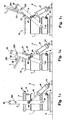
- the lid (2) is associated with the body (1) by a connecting hinge (21) and by a fork structure comprising two diametrally opposite arms (3) which, in correspondence or in the vicinity of the respective free ends are connected to the container (1) via transverse hinges (31); in practice, the axis of each hinge (31) is orthogonal to the respective arm (3) and is parallel to that of said hinge (21), the latter linking the lid (2) to the body of the container (1).
- the two arms (3) are joined on top by a crosspiece (30).
- a lever (33) is connected to the two arms (3), said lever being in turn connected to an upper appendix (32) of lid (2).
- the connection between the lever (33) and the arms (3) is made via a hinge (330).
- the connection between the lever (33) and the lid (2) is made via a hinge (320).
- the axes of all the hinges above indicated are parallel to each other.
- the said fork structure is engaged with a cylinder actuator (4).
- the latter is connected to one of the two arms (3) of the structure. More specifically, and as illustrated in the figures of the attached drawings, the rod (40) of actuator (4) is engaged with one of the arms (3) via a corresponding hinge (43), the shell (41) of cylinder (4) being engaged, via a corresponding hinge (44), with a bearing plane (P) which supports also the tank's body (1).
- the axes of hinges (43, 44) are parallel to each other and to the axes of the other hinges mentioned above.
- the rod (40) of actuator (4) is driven backwards.
- the rod (4) is driven outwardly.
- the hinges (43) and (330) can be offset, that is, put out of alignment, with the hinge (330) being at a distance from hinge (21) longer than from hinge (43), thereby allowing a higher operational safety, that is, preventing the spontaneous opening of the lid (2) possibly due to the pressure exerted onto the inner surface thereof by the vapors which form as a consequence of heating the dyeing bath within the tank.
- two adjustable screw pins (331) are provided on the body (32) of the hinge (320) located on the lid (2), said screw pins going through the same body and their ends making up a stop means against which the lever (33) is made to abut upon closing the lid (2). In this way, the angular position ( ⁇ ) of lever (33) upon closing the lid (2) can be adjusted at will.
- the spontaneous lifting of the lid (2) is prevented by the pressure inside the tank even if the actuator (4) is not driven, that is, also in case the forces determining the closing of the lid (2) are not present.
- the tank's body (1) is provided with mouths (H, K) of known type for the introduction of fluids intended for heating/cooling the tank and for the circulation of the dyeing bath.
- a nozzle (20) can be associated with the tank's lid (2) for feeding a service fluid, such as a colouring substance, via a hose (22) connected with a pump of known type and not described nor illustrated in detail.
- a service fluid such as a colouring substance
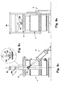
- the materials to be dyed may be, for example, rolls or patches of fabric held in perforated basket (5) - as shown in Figs. 2A-2G, or reels of yarn fitted on reel-holders (6), as shown in Figs. 4A-4C.
- a mechanical arm (7) known per se to those skilled in the art - able to remove the baskets (5) and the reel-holders (6) from a standby plane (P) to dispose them into the tank and, upon completion of the dyeing cycle, removing same baskets from the tank and dispose them onto said plane (P) or another plane (for example, a plane onto which the baskets and reel-holders with treated materials are disposed).
- the said arm (7) is provided at the bottom with a grip section (70) intended for engaging an upper appendix (51; 61) of the basket (5) or of the reel-holder (6) upon the hooking thereof, and disengaging it upon the release step.
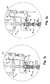
- the said grip section (70) of arm (7) comprises a bush with lead-in mouth (71) to be fitted onto the said appendix (51; 61) upon hooking either the basket or reel-holder, with an intermediate cylindrical portion and a rear conical portion followed by a further cylindrical portion.
- the bush (71) receives a plurality of balls (72) onto which a spring (73), also housed inside the rear cylindrical portion of the same bush (71), is made to act from above.
- Acting on the spring (73) is a lever (74) which is operated by a pneumatic actuator (75) mounted on the same arm (7), that is, engaged with a corresponding support bracket (76). When the lever (74) is in horizontal position, as shown in Fig.
- the spring (73) causes the balls (72) to press the corrugated surface of appendix (51; 61) exhibetd by the basket (5) or by the reel-holder (6).
- the lever (74) is rotated upwards, as in Fig. 3B, the balls (72) are no longer acted upon by the spring (73) and, as a consequence, the said appendix is released.
- the unit (70) upon hooking a basket (5) or a reel-holder (6), the unit (70) takes up the configuration of Fig. 3A.
- the unit (70) takes up the configuration of Fig. 3B.
- the said arm (7) is mounted on a movable support (77) allowing the positioning of same arm (7), and thus of the engagement/disengagement unit (70), in correspondence of the resting sites of baskets (5) and reel-holders (6) and in correspondence of tank (1).
- the said movable support (77) is engaged with electric motors (not shown) by using connection means of known type, said motors being in turn engaged with a programmable control unit also of known type and which operates the actuator (4) for causing either the opening/closing of the tank's lid (2), upon the arrival of baskets (5) or reel-holders (6) during the loading step, or the removal thereof during the unloading step, that is upon completion of the dyeing.
Landscapes
- Engineering & Computer Science (AREA)
- Textile Engineering (AREA)
- General Engineering & Computer Science (AREA)
- Mechanical Engineering (AREA)
- Treatment Of Fiber Materials (AREA)
- Coloring (AREA)
Claims (7)
- Behälter zum Färben von Textilmaterialien, enthaltend einen Aufnahmekörper (1) mit einer vertikalen Achse und einer oberen Öffnung (10) zum Einfüllen von Färbeflüssigkeit und der Materialien in den genannten Körper (1) und jeweils zum Herausnehmen derselben, sowie einen unteren, auf einer Standebene (P) aufliegenden Sockel, und einen Deckel (2) der genannten Öffnung (10), wobei der genannte Behälter (1) ausserdem Öffnungs- und jeweils Schliessmittel mit einem Antrieb (4) enthält, der auf den genannten Deckel (2) mit Hilfe von Mitteln wirkt, enthaltend einen Arm (3), wobei der genannte Antrieb (4) mit dem genannten Arm (3) über ein Scharnier (43) verbunden ist, dadurch gekennzeichnet, dass der genannte Deckel (2) mit dem Körper (1) mit Hilfe eines Scharniers (21) verbunden ist, und dass der genannte Arm (3) mit einem Ende mit dem Körper (1) über ein Scharnier (31) verbunden ist, dessen Achse parallel zu der des Scharniers (21) verläuft, welches den Deckel (2) mit dem Körper (1) verbindet, und mit dem anderen Ende mit dem Deckel (2) über einen Hebel (33), wobei der genannte Hebel (33) mit einem Ende über ein Scharnier (330) an den genannten Arm (3) angelenkt ist und mit dem anderen Ende über ein Scharnier (320) an den genannten Deckel (2), und wobei im geschlossenen Zustand der genannte Deckel (2) in einer Position zwischen dem genannten, den genannten Hebel (33) und den genannten Arm (3) verbindenden Scharnier (330) und dem genannten Scharnier (31) angeordnet ist, durch welches Arm (3) an den Körper (1) anlenkt ist.
- Behälter nach Patentanspruch 1, dadurch gekennzeichnet, dass der genannte Arm (3) Teil einer Gabelstruktur ist, enthaltend zwei einander gegenüberliegende Arme, die durch ein Querstück (30) miteinander verbunden sind.
- Behälter nach Patentanspruch 1, dadurch gekennzeichnet, dass der genannte Antrieb (4) an einer Fläche befestigt ist, welche als Stütze für den Behälter wirkt.
- Behälter nach Patentanspruch 1, dadurch gekennzeichnet, dass der genannte Deckel (2) mit einer Düse (20) zum Eingeben einer Betriebsflüssigkeit in den Behälter versehen ist.
- Behälter nach Patentanspruch 1, dadurch gekennzeichnet, dass die Winkelposition (α) des genannten Hebels (33) nach dem Schliessen desselben Behälters einstellbar ist.
- Behälter nach Patentanspruch 1, dadurch gekennzeichnet, dass das genannte, den genannten Arm (3) mit dem genannten Antrieb (4) verbindende Scharnier (43) und das genannte, den genannten Hebel (33) mit dem genannten Arm (3) verbindende Scharnier (330) im Verhältnis zu dem genannten Scharnier (320), welches ein Ende des genannten Hebels (33) mit dem genannten Deckel (2) verbindet, versetzt sind, um das Öffnen des genannten Deckels (2) beim Fehlen der zum Schliessen des genannten Behälters ausgeübten Kräfte zu verhindern.
- Vorrichtung zum Färben von Textilmaterialien, enthaltend einen Behälter (1) nach Patentanspruch 1, sowie weiter enthaltend Mittel (7) zum automatischen Positionieren eines Korbes (5) oder eines Spulenhalters (6) darin.
Applications Claiming Priority (2)
| Application Number | Priority Date | Filing Date | Title |
|---|---|---|---|
| ITFI20020046 | 2002-03-13 | ||
| IT2002FI000046A ITFI20020046A1 (it) | 2002-03-13 | 2002-03-13 | Vasca per la tintura di materiali tessili |
Publications (3)
| Publication Number | Publication Date |
|---|---|
| EP1344860A2 EP1344860A2 (de) | 2003-09-17 |
| EP1344860A3 EP1344860A3 (de) | 2005-01-19 |
| EP1344860B1 true EP1344860B1 (de) | 2007-09-26 |
Family
ID=27764158
Family Applications (1)
| Application Number | Title | Priority Date | Filing Date |
|---|---|---|---|
| EP03425109A Expired - Lifetime EP1344860B1 (de) | 2002-03-13 | 2003-02-24 | Behälter zum Färben von Textilmaterialen |
Country Status (6)
| Country | Link |
|---|---|
| US (1) | US20030172687A1 (de) |
| EP (1) | EP1344860B1 (de) |
| CN (1) | CN100422422C (de) |
| AT (1) | ATE374272T1 (de) |
| DE (1) | DE60316489T2 (de) |
| IT (1) | ITFI20020046A1 (de) |
Families Citing this family (9)
| Publication number | Priority date | Publication date | Assignee | Title |
|---|---|---|---|---|
| US8295970B2 (en) | 2007-03-21 | 2012-10-23 | Tintoria Piana U.S., Inc. | Customer-created textiles and customer-oriented garment dyeing machine |
| US7788754B2 (en) * | 2007-03-21 | 2010-09-07 | Tintoria Piana Us, Inc. | Customer-created textiles and customer-oriented garment dyeing machine |
| US9821953B2 (en) * | 2011-05-02 | 2017-11-21 | The Charles Machine Works, Inc. | Apparatus for sealing a vacuum tank door |
| CN102367870A (zh) * | 2011-09-09 | 2012-03-07 | 贵州风雷航空军械有限责任公司 | 快开门装置 |
| CN102587054B (zh) * | 2012-03-13 | 2014-05-07 | 机械科学研究总院先进制造技术研究中心 | 缸盖自动锁紧装置及包括该装置的筒子纱染色机 |
| CN104499231B (zh) * | 2014-10-27 | 2016-06-08 | 成都瑞克西自动化技术有限公司 | 染色机自动启闭门 |
| US10221602B2 (en) * | 2016-04-06 | 2019-03-05 | The Charles Machine Works, Inc. | Vacuum system |
| CN117661209B (zh) * | 2024-02-01 | 2024-04-23 | 兴化市俊达纱线有限公司 | 一种纱线上色设备 |
| IT202400003838A1 (it) * | 2024-02-23 | 2025-08-23 | Galvanin S P A | “pinza per asta portarocche” |
Family Cites Families (28)
| Publication number | Priority date | Publication date | Assignee | Title |
|---|---|---|---|---|
| BE397012A (de) * | ||||
| US1332257A (en) * | 1919-08-25 | 1920-03-02 | John H Hendrickson | Laundry-machine |
| US1874833A (en) * | 1930-05-29 | 1932-08-30 | Albert L Taylor | Process retort |
| US2529478A (en) * | 1946-01-07 | 1950-11-14 | American Can Co | Casing door operator |
| US2639601A (en) * | 1949-12-15 | 1953-05-26 | Miller Herman | Swingable door for tumbler type clothes washing machines |
| US2823602A (en) * | 1952-06-05 | 1958-02-18 | Internat Laundry Machinery Co | Method and apparatus for washing and water-extracting clothes |
| US2774506A (en) * | 1956-05-03 | 1956-12-18 | Miller Laundry Company | Door constructions for laundry machinery |
| US3011327A (en) * | 1961-05-22 | 1961-12-05 | Turbo Machine Co | Apparatus for setting textile fibers |
| US3144165A (en) * | 1962-08-29 | 1964-08-11 | Turbon Machine Company | Locking means for pressure vessel |
| GB1036813A (en) * | 1963-01-18 | 1966-07-20 | Barriquand Freres Ets | Machine for the wet treatment of textile materials or the like |
| US3406997A (en) * | 1966-09-22 | 1968-10-22 | Riggs & Lombard Inc | Pressure door locking mechanism |
| FR1531485A (fr) * | 1967-05-03 | 1968-07-05 | Procédé de nettoyage, notamment d'articles textiles, et appareillage en permettantla mise en oeuvre | |
| US3494219A (en) * | 1968-01-19 | 1970-02-10 | Tasope Ltd | Linkage assembly for lifting the lid of a container |
| GB1258076A (de) * | 1968-04-05 | 1971-12-22 | ||
| CH625744A5 (de) * | 1978-04-04 | 1981-10-15 | Fischer Georg Brugg Oehler Ag | |
| US4199238A (en) * | 1979-03-12 | 1980-04-22 | Boudreau Jon P | Miniature camera probe |
| US4334633A (en) * | 1981-04-06 | 1982-06-15 | Wsf Industries, Inc. | Articulated door |
| US4722295A (en) * | 1985-04-29 | 1988-02-02 | Ultraseal International Limited | Article treating apparatus |
| US5259930A (en) * | 1989-02-21 | 1993-11-09 | Atlantic Richfield Company | Method for operation of automated top head and stem guide assembly for coking drums |
| US5288521A (en) * | 1989-10-25 | 1994-02-22 | Hubert Maldaner | Process and apparatus for the impregnation of workpieces of porous material |
| CN2110612U (zh) * | 1991-11-15 | 1992-07-22 | 松江县农业机械研究所 | 开闭盖机构 |
| US5495730A (en) * | 1993-04-19 | 1996-03-05 | Gaston County Dyeing Machine Company | Adapter for using a horizontal package dyeing carrier with a vertical treatment machine |
| JP2675522B2 (ja) * | 1994-04-27 | 1997-11-12 | 株式会社羽生田鉄工 | 圧力容器の蓋開閉装置 |
| IT1295153B1 (it) * | 1997-08-14 | 1999-04-30 | Tecnorama Srl | Apparecchiatura automatica per la tintura di materiali tessili |
| EP1017894B1 (de) * | 1997-09-26 | 2002-06-05 | Loris Bellini S.p.A. | Einrichtung zur behandlung von garnspulen |
| IT1317519B1 (it) * | 2000-05-11 | 2003-07-09 | Loris Bellini S P A | Macchina e impianto per la tintura di capi |
| CN2490188Y (zh) * | 2001-04-23 | 2002-05-08 | 崔关林 | 染色机大浴比回流式化料装置 |
| ITFI20020045A1 (it) * | 2002-03-13 | 2003-09-15 | Tecnorama Srl | Cestello e procedimento per la tintura di materiali tessili |
-
2002
- 2002-03-13 IT IT2002FI000046A patent/ITFI20020046A1/it unknown
-
2003
- 2003-02-24 AT AT03425109T patent/ATE374272T1/de not_active IP Right Cessation
- 2003-02-24 EP EP03425109A patent/EP1344860B1/de not_active Expired - Lifetime
- 2003-02-24 DE DE60316489T patent/DE60316489T2/de not_active Expired - Fee Related
- 2003-03-04 US US10/379,350 patent/US20030172687A1/en not_active Abandoned
- 2003-03-13 CN CNB031205356A patent/CN100422422C/zh not_active Expired - Fee Related
Also Published As
| Publication number | Publication date |
|---|---|
| EP1344860A3 (de) | 2005-01-19 |
| CN1443891A (zh) | 2003-09-24 |
| CN100422422C (zh) | 2008-10-01 |
| EP1344860A2 (de) | 2003-09-17 |
| ATE374272T1 (de) | 2007-10-15 |
| ITFI20020046A1 (it) | 2003-09-15 |
| US20030172687A1 (en) | 2003-09-18 |
| DE60316489T2 (de) | 2008-07-03 |
| DE60316489D1 (de) | 2007-11-08 |
Similar Documents
| Publication | Publication Date | Title |
|---|---|---|
| JP6193435B2 (ja) | 型ドラムの洗浄方法 | |
| EP1344860A2 (de) | Behälter zum Färben von Textilmaterialen | |
| KR20130123544A (ko) | 드럼 세탁기의 도어장치 | |
| EP0897031B1 (de) | Automatische Vorrichtung zum Färben von Textilgut | |
| US7313935B2 (en) | Dying or bleaching apparatus for yarn wound on reels or similar packages | |
| KR101518396B1 (ko) | 그라데이션 염색방법 | |
| ITMI20001048A1 (it) | Macchina e impianto per la tintura di capi | |
| EP0640711B1 (de) | Verfahren und Vorrichtung zum Entbasten von Seidengeweben | |
| EP1602764B1 (de) | Korb, Maschine und Anlage zum Färben von Textilmaterialien | |
| KR101519115B1 (ko) | 그라데이션 염색장치 | |
| EP1344859A2 (de) | Korb und Verfahren zum Färben von Textilmaterialen | |
| EP1693172B1 (de) | Verfahren und Gerät zum Imprägnieren von Korken | |
| US4231236A (en) | Dyeing machine, particularly for dyeing and drying stocking articles and like garments | |
| US4360431A (en) | Self-unloading centrifuge | |
| US5495730A (en) | Adapter for using a horizontal package dyeing carrier with a vertical treatment machine | |
| KR920701542A (ko) | 캅의 열처리 및/또는 조습처리 | |
| CN220057300U (zh) | 一种纺织布料的印染装置 | |
| CN220907917U (zh) | 一种经轴筒滴漏自动排水结构 | |
| EP0635594A2 (de) | Verfahren und Maschine zum Färben von konfektionierten Bekleidungsstücken | |
| JPS636668B2 (de) | ||
| CN112301590A (zh) | 一种自动开盖出料的筒纱染色缸 | |
| EP1561850A1 (de) | Völlig automatisiertes Garnfärbsystem | |
| IT202400003838A1 (it) | “pinza per asta portarocche” | |
| HK1064135B (en) | Dying or bleaching apparatus for yarn wound on reels or similar packages | |
| KR20190065048A (ko) | 세탁물 처리기기 |
Legal Events
| Date | Code | Title | Description |
|---|---|---|---|
| PUAI | Public reference made under article 153(3) epc to a published international application that has entered the european phase |
Free format text: ORIGINAL CODE: 0009012 |
|
| AK | Designated contracting states |
Kind code of ref document: A2 Designated state(s): AT BE BG CH CY CZ DE DK EE ES FI FR GB GR HU IE IT LI LU MC NL PT SE SI SK TR |
|
| AX | Request for extension of the european patent |
Extension state: AL LT LV MK RO |
|
| PUAL | Search report despatched |
Free format text: ORIGINAL CODE: 0009013 |
|
| RIC1 | Information provided on ipc code assigned before grant |
Ipc: 7F 16J 13/18 B Ipc: 7D 06B 23/14 A |
|
| AK | Designated contracting states |
Kind code of ref document: A3 Designated state(s): AT BE BG CH CY CZ DE DK EE ES FI FR GB GR HU IE IT LI LU MC NL PT SE SI SK TR |
|
| AX | Request for extension of the european patent |
Extension state: AL LT LV MK RO |
|
| 17P | Request for examination filed |
Effective date: 20050321 |
|
| AKX | Designation fees paid |
Designated state(s): AT BE BG CH CY CZ DE DK EE ES FI FR GB GR HU IE IT LI LU MC NL PT SE SI SK TR |
|
| 17Q | First examination report despatched |
Effective date: 20060710 |
|
| GRAP | Despatch of communication of intention to grant a patent |
Free format text: ORIGINAL CODE: EPIDOSNIGR1 |
|
| GRAS | Grant fee paid |
Free format text: ORIGINAL CODE: EPIDOSNIGR3 |
|
| GRAA | (expected) grant |
Free format text: ORIGINAL CODE: 0009210 |
|
| AK | Designated contracting states |
Kind code of ref document: B1 Designated state(s): AT BE BG CH CY CZ DE DK EE ES FI FR GB GR HU IE IT LI LU MC NL PT SE SI SK TR |
|
| REG | Reference to a national code |
Ref country code: GB Ref legal event code: FG4D |
|
| REG | Reference to a national code |
Ref country code: CH Ref legal event code: EP |
|
| REF | Corresponds to: |
Ref document number: 60316489 Country of ref document: DE Date of ref document: 20071108 Kind code of ref document: P |
|
| REG | Reference to a national code |
Ref country code: IE Ref legal event code: FG4D |
|
| PG25 | Lapsed in a contracting state [announced via postgrant information from national office to epo] |
Ref country code: FI Free format text: LAPSE BECAUSE OF FAILURE TO SUBMIT A TRANSLATION OF THE DESCRIPTION OR TO PAY THE FEE WITHIN THE PRESCRIBED TIME-LIMIT Effective date: 20070926 |
|
| PG25 | Lapsed in a contracting state [announced via postgrant information from national office to epo] |
Ref country code: AT Free format text: LAPSE BECAUSE OF FAILURE TO SUBMIT A TRANSLATION OF THE DESCRIPTION OR TO PAY THE FEE WITHIN THE PRESCRIBED TIME-LIMIT Effective date: 20070926 |
|
| NLV1 | Nl: lapsed or annulled due to failure to fulfill the requirements of art. 29p and 29m of the patents act | ||
| PG25 | Lapsed in a contracting state [announced via postgrant information from national office to epo] |
Ref country code: BE Free format text: LAPSE BECAUSE OF FAILURE TO SUBMIT A TRANSLATION OF THE DESCRIPTION OR TO PAY THE FEE WITHIN THE PRESCRIBED TIME-LIMIT Effective date: 20070926 |
|
| REG | Reference to a national code |
Ref country code: CH Ref legal event code: PL |
|
| PG25 | Lapsed in a contracting state [announced via postgrant information from national office to epo] |
Ref country code: LI Free format text: LAPSE BECAUSE OF FAILURE TO SUBMIT A TRANSLATION OF THE DESCRIPTION OR TO PAY THE FEE WITHIN THE PRESCRIBED TIME-LIMIT Effective date: 20070926 Ref country code: ES Free format text: LAPSE BECAUSE OF FAILURE TO SUBMIT A TRANSLATION OF THE DESCRIPTION OR TO PAY THE FEE WITHIN THE PRESCRIBED TIME-LIMIT Effective date: 20080106 Ref country code: CH Free format text: LAPSE BECAUSE OF FAILURE TO SUBMIT A TRANSLATION OF THE DESCRIPTION OR TO PAY THE FEE WITHIN THE PRESCRIBED TIME-LIMIT Effective date: 20070926 Ref country code: NL Free format text: LAPSE BECAUSE OF FAILURE TO SUBMIT A TRANSLATION OF THE DESCRIPTION OR TO PAY THE FEE WITHIN THE PRESCRIBED TIME-LIMIT Effective date: 20070926 Ref country code: GR Free format text: LAPSE BECAUSE OF FAILURE TO SUBMIT A TRANSLATION OF THE DESCRIPTION OR TO PAY THE FEE WITHIN THE PRESCRIBED TIME-LIMIT Effective date: 20071227 |
|
| PG25 | Lapsed in a contracting state [announced via postgrant information from national office to epo] |
Ref country code: CZ Free format text: LAPSE BECAUSE OF FAILURE TO SUBMIT A TRANSLATION OF THE DESCRIPTION OR TO PAY THE FEE WITHIN THE PRESCRIBED TIME-LIMIT Effective date: 20070926 Ref country code: SK Free format text: LAPSE BECAUSE OF FAILURE TO SUBMIT A TRANSLATION OF THE DESCRIPTION OR TO PAY THE FEE WITHIN THE PRESCRIBED TIME-LIMIT Effective date: 20070926 Ref country code: PT Free format text: LAPSE BECAUSE OF FAILURE TO SUBMIT A TRANSLATION OF THE DESCRIPTION OR TO PAY THE FEE WITHIN THE PRESCRIBED TIME-LIMIT Effective date: 20080226 |
|
| PGFP | Annual fee paid to national office [announced via postgrant information from national office to epo] |
Ref country code: DE Payment date: 20080221 Year of fee payment: 6 Ref country code: IT Payment date: 20080228 Year of fee payment: 6 |
|
| PG25 | Lapsed in a contracting state [announced via postgrant information from national office to epo] |
Ref country code: SE Free format text: LAPSE BECAUSE OF FAILURE TO SUBMIT A TRANSLATION OF THE DESCRIPTION OR TO PAY THE FEE WITHIN THE PRESCRIBED TIME-LIMIT Effective date: 20071226 |
|
| EN | Fr: translation not filed | ||
| PG25 | Lapsed in a contracting state [announced via postgrant information from national office to epo] |
Ref country code: DK Free format text: LAPSE BECAUSE OF FAILURE TO SUBMIT A TRANSLATION OF THE DESCRIPTION OR TO PAY THE FEE WITHIN THE PRESCRIBED TIME-LIMIT Effective date: 20070926 |
|
| PLBE | No opposition filed within time limit |
Free format text: ORIGINAL CODE: 0009261 |
|
| STAA | Information on the status of an ep patent application or granted ep patent |
Free format text: STATUS: NO OPPOSITION FILED WITHIN TIME LIMIT |
|
| 26N | No opposition filed |
Effective date: 20080627 |
|
| PGFP | Annual fee paid to national office [announced via postgrant information from national office to epo] |
Ref country code: TR Payment date: 20080211 Year of fee payment: 6 |
|
| GBPC | Gb: european patent ceased through non-payment of renewal fee |
Effective date: 20080224 |
|
| PG25 | Lapsed in a contracting state [announced via postgrant information from national office to epo] |
Ref country code: FR Free format text: LAPSE BECAUSE OF FAILURE TO SUBMIT A TRANSLATION OF THE DESCRIPTION OR TO PAY THE FEE WITHIN THE PRESCRIBED TIME-LIMIT Effective date: 20080704 Ref country code: MC Free format text: LAPSE BECAUSE OF NON-PAYMENT OF DUE FEES Effective date: 20080228 |
|
| PG25 | Lapsed in a contracting state [announced via postgrant information from national office to epo] |
Ref country code: EE Free format text: LAPSE BECAUSE OF FAILURE TO SUBMIT A TRANSLATION OF THE DESCRIPTION OR TO PAY THE FEE WITHIN THE PRESCRIBED TIME-LIMIT Effective date: 20070926 Ref country code: IE Free format text: LAPSE BECAUSE OF NON-PAYMENT OF DUE FEES Effective date: 20080225 |
|
| PG25 | Lapsed in a contracting state [announced via postgrant information from national office to epo] |
Ref country code: SI Free format text: LAPSE BECAUSE OF FAILURE TO SUBMIT A TRANSLATION OF THE DESCRIPTION OR TO PAY THE FEE WITHIN THE PRESCRIBED TIME-LIMIT Effective date: 20070926 Ref country code: GB Free format text: LAPSE BECAUSE OF NON-PAYMENT OF DUE FEES Effective date: 20080224 |
|
| PG25 | Lapsed in a contracting state [announced via postgrant information from national office to epo] |
Ref country code: CY Free format text: LAPSE BECAUSE OF FAILURE TO SUBMIT A TRANSLATION OF THE DESCRIPTION OR TO PAY THE FEE WITHIN THE PRESCRIBED TIME-LIMIT Effective date: 20070926 |
|
| PG25 | Lapsed in a contracting state [announced via postgrant information from national office to epo] |
Ref country code: BG Free format text: LAPSE BECAUSE OF FAILURE TO SUBMIT A TRANSLATION OF THE DESCRIPTION OR TO PAY THE FEE WITHIN THE PRESCRIBED TIME-LIMIT Effective date: 20071226 |
|
| PG25 | Lapsed in a contracting state [announced via postgrant information from national office to epo] |
Ref country code: DE Free format text: LAPSE BECAUSE OF NON-PAYMENT OF DUE FEES Effective date: 20090901 |
|
| PG25 | Lapsed in a contracting state [announced via postgrant information from national office to epo] |
Ref country code: LU Free format text: LAPSE BECAUSE OF NON-PAYMENT OF DUE FEES Effective date: 20080224 Ref country code: HU Free format text: LAPSE BECAUSE OF FAILURE TO SUBMIT A TRANSLATION OF THE DESCRIPTION OR TO PAY THE FEE WITHIN THE PRESCRIBED TIME-LIMIT Effective date: 20080327 |
|
| PG25 | Lapsed in a contracting state [announced via postgrant information from national office to epo] |
Ref country code: IT Free format text: LAPSE BECAUSE OF NON-PAYMENT OF DUE FEES Effective date: 20090224 |
|
| PG25 | Lapsed in a contracting state [announced via postgrant information from national office to epo] |
Ref country code: TR Free format text: LAPSE BECAUSE OF NON-PAYMENT OF DUE FEES Effective date: 20090224 |