EP1344867A2 - Unterflurleuchte - Google Patents
Unterflurleuchte Download PDFInfo
- Publication number
- EP1344867A2 EP1344867A2 EP03003334A EP03003334A EP1344867A2 EP 1344867 A2 EP1344867 A2 EP 1344867A2 EP 03003334 A EP03003334 A EP 03003334A EP 03003334 A EP03003334 A EP 03003334A EP 1344867 A2 EP1344867 A2 EP 1344867A2
- Authority
- EP
- European Patent Office
- Prior art keywords
- light
- underfloor
- prism
- horizontal
- housing
- Prior art date
- Legal status (The legal status is an assumption and is not a legal conclusion. Google has not performed a legal analysis and makes no representation as to the accuracy of the status listed.)
- Withdrawn
Links
- 230000001154 acute effect Effects 0.000 claims description 3
- 230000003287 optical effect Effects 0.000 description 5
- 238000005299 abrasion Methods 0.000 description 4
- 238000004140 cleaning Methods 0.000 description 4
- 238000011161 development Methods 0.000 description 4
- 230000018109 developmental process Effects 0.000 description 4
- 230000000694 effects Effects 0.000 description 4
- 238000004519 manufacturing process Methods 0.000 description 4
- 230000015572 biosynthetic process Effects 0.000 description 3
- 239000002245 particle Substances 0.000 description 3
- 230000005855 radiation Effects 0.000 description 3
- 238000005096 rolling process Methods 0.000 description 3
- XLYOFNOQVPJJNP-UHFFFAOYSA-N water Substances O XLYOFNOQVPJJNP-UHFFFAOYSA-N 0.000 description 3
- 230000008878 coupling Effects 0.000 description 2
- 238000010168 coupling process Methods 0.000 description 2
- 238000005859 coupling reaction Methods 0.000 description 2
- 230000006378 damage Effects 0.000 description 2
- 230000006866 deterioration Effects 0.000 description 2
- 238000009434 installation Methods 0.000 description 2
- 238000012423 maintenance Methods 0.000 description 2
- 230000011664 signaling Effects 0.000 description 2
- 238000012549 training Methods 0.000 description 2
- 230000001133 acceleration Effects 0.000 description 1
- 230000002411 adverse Effects 0.000 description 1
- 239000003086 colorant Substances 0.000 description 1
- 238000011109 contamination Methods 0.000 description 1
- 238000005260 corrosion Methods 0.000 description 1
- 230000007797 corrosion Effects 0.000 description 1
- 238000013461 design Methods 0.000 description 1
- 238000010586 diagram Methods 0.000 description 1
- 230000002349 favourable effect Effects 0.000 description 1
- 230000004313 glare Effects 0.000 description 1
- 239000011521 glass Substances 0.000 description 1
- 239000003550 marker Substances 0.000 description 1
- 239000000463 material Substances 0.000 description 1
- 239000002184 metal Substances 0.000 description 1
- 238000000034 method Methods 0.000 description 1
- 230000011218 segmentation Effects 0.000 description 1
- 239000005341 toughened glass Substances 0.000 description 1
- 230000007704 transition Effects 0.000 description 1
Images


Classifications
-
- B—PERFORMING OPERATIONS; TRANSPORTING
- B64—AIRCRAFT; AVIATION; COSMONAUTICS
- B64F—GROUND OR AIRCRAFT-CARRIER-DECK INSTALLATIONS SPECIALLY ADAPTED FOR USE IN CONNECTION WITH AIRCRAFT; DESIGNING, MANUFACTURING, ASSEMBLING, CLEANING, MAINTAINING OR REPAIRING AIRCRAFT, NOT OTHERWISE PROVIDED FOR; HANDLING, TRANSPORTING, TESTING OR INSPECTING AIRCRAFT COMPONENTS, NOT OTHERWISE PROVIDED FOR
- B64F1/00—Ground or aircraft-carrier-deck installations
- B64F1/18—Visual or acoustic landing aids
- B64F1/20—Arrangement of optical beacons
- B64F1/205—Arrangement of optical beacons arranged underground, e.g. underground runway lighting units
-
- B—PERFORMING OPERATIONS; TRANSPORTING
- B64—AIRCRAFT; AVIATION; COSMONAUTICS
- B64F—GROUND OR AIRCRAFT-CARRIER-DECK INSTALLATIONS SPECIALLY ADAPTED FOR USE IN CONNECTION WITH AIRCRAFT; DESIGNING, MANUFACTURING, ASSEMBLING, CLEANING, MAINTAINING OR REPAIRING AIRCRAFT, NOT OTHERWISE PROVIDED FOR; HANDLING, TRANSPORTING, TESTING OR INSPECTING AIRCRAFT COMPONENTS, NOT OTHERWISE PROVIDED FOR
- B64F1/00—Ground or aircraft-carrier-deck installations
- B64F1/18—Visual or acoustic landing aids
- B64F1/20—Arrangement of optical beacons
-
- E—FIXED CONSTRUCTIONS
- E01—CONSTRUCTION OF ROADS, RAILWAYS, OR BRIDGES
- E01F—ADDITIONAL WORK, SUCH AS EQUIPPING ROADS OR THE CONSTRUCTION OF PLATFORMS, HELICOPTER LANDING STAGES, SIGNS, SNOW FENCES, OR THE LIKE
- E01F9/00—Arrangement of road signs or traffic signals; Arrangements for enforcing caution
- E01F9/20—Use of light guides, e.g. fibre-optic devices
-
- E—FIXED CONSTRUCTIONS
- E01—CONSTRUCTION OF ROADS, RAILWAYS, OR BRIDGES
- E01F—ADDITIONAL WORK, SUCH AS EQUIPPING ROADS OR THE CONSTRUCTION OF PLATFORMS, HELICOPTER LANDING STAGES, SIGNS, SNOW FENCES, OR THE LIKE
- E01F9/00—Arrangement of road signs or traffic signals; Arrangements for enforcing caution
- E01F9/50—Road surface markings; Kerbs or road edgings, specially adapted for alerting road users
- E01F9/553—Low discrete bodies, e.g. marking blocks, studs or flexible vehicle-striking members
- E01F9/559—Low discrete bodies, e.g. marking blocks, studs or flexible vehicle-striking members illuminated
-
- F—MECHANICAL ENGINEERING; LIGHTING; HEATING; WEAPONS; BLASTING
- F21—LIGHTING
- F21V—FUNCTIONAL FEATURES OR DETAILS OF LIGHTING DEVICES OR SYSTEMS THEREOF; STRUCTURAL COMBINATIONS OF LIGHTING DEVICES WITH OTHER ARTICLES, NOT OTHERWISE PROVIDED FOR
- F21V5/00—Refractors for light sources
- F21V5/02—Refractors for light sources of prismatic shape
-
- F—MECHANICAL ENGINEERING; LIGHTING; HEATING; WEAPONS; BLASTING
- F21—LIGHTING
- F21W—INDEXING SCHEME ASSOCIATED WITH SUBCLASSES F21K, F21L, F21S and F21V, RELATING TO USES OR APPLICATIONS OF LIGHTING DEVICES OR SYSTEMS
- F21W2111/00—Use or application of lighting devices or systems for signalling, marking or indicating, not provided for in codes F21W2102/00 – F21W2107/00
- F21W2111/06—Use or application of lighting devices or systems for signalling, marking or indicating, not provided for in codes F21W2102/00 – F21W2107/00 for aircraft runways or the like
-
- F—MECHANICAL ENGINEERING; LIGHTING; HEATING; WEAPONS; BLASTING
- F21—LIGHTING
- F21Y—INDEXING SCHEME ASSOCIATED WITH SUBCLASSES F21K, F21L, F21S and F21V, RELATING TO THE FORM OR THE KIND OF THE LIGHT SOURCES OR OF THE COLOUR OF THE LIGHT EMITTED
- F21Y2115/00—Light-generating elements of semiconductor light sources
- F21Y2115/10—Light-emitting diodes [LED]
Definitions
- the invention relates to an underfloor lamp according to the preamble of claim 1.
- Such an underfloor light is for example from DE 198 09 253 A1 known.
- This underfloor lamp has one out Upper and lower part formed housing for receiving a translucent cover and a light source and / or a light-guiding optic.
- the upper part has a detachable one Use, with the translucent cover in use is arranged.
- the insert essentially has on its top two surfaces inclined towards each other, namely one relative to the upper part approximately horizontal surface and a then one-sided and off-center, downward inclined Sloping surface, the sloping surface being an opening (Breakthrough) to accommodate the translucent cover has.
- the translucent cover adjusts (only) Prism from which the light in a certain direction, especially with an acute angle to the horizontal exit.
- the prism faces the incoming light an entry surface perpendicular to this and opposite the exiting one Light an oblique exit surface, whereby the entry surface is one point sharp in relation to a vertical Angle is inclined.
- the exit surface of the prism lies approximately horizontal and is essentially flush or plane-parallel to the off-center adjoining downward sloping surface, which in turn is almost parallel runs to the horizontal, at least in relation to the horizontal is only slightly inclined.
- the underfloor lamp known from DE 198 09 253 A1 has the following disadvantages. Because of the arrangement of prism or its exit surface and the itself subsequent horizontal and sloping surfaces on the top of use is that of fragile material in particular Toughened glass prism practically unprotected over the the underfloor light exposed to rolling vehicles. by virtue of today's high axle loads of road vehicles the prism of the known type is not sufficiently stable and mechanically resilient. The translucent Cover may be more or less on its surface wear heavily, and eventually lose transparency.
- the in the area of the exit surface of the translucent Coverage can remain and the optical radiation properties adversely affected, and at the worst Case for undesirable glare to road users can lead if the upwards or diagonally from the horizontal directed portion of the emitted light beam due to reflection and diffraction at the wear particles increases. Due to the arrangement of the translucent Coverage is that emitted in the horizontal direction Light output anyway lower and therefore already unfavorable.
- the translucent on the exit surface Coverage due to the less favorable geometry the known underfloor light dirt, pebbles and the like Foreign bodies, and especially rain and splash water collect, and on the one hand a mechanical hazard to the translucent cover, and at least deterioration the optical properties of the translucent Also pull the cover.
- the object of the invention is the generic underfloor light for use in general road traffic to improve that with the smallest possible height of the Underfloor light a much higher light output of the in essentially light beam emitted in the horizontal direction is possible, and there is a risk of pollution or endanger the optical properties and Ease of maintenance and thus longer service life of the underfloor lamp is guaranteed.
- the underfloor light according to the invention is characterized by this from that in the top part a substantially horizontal, i.e. at most slightly downward inclined to the horizontal, and opposite the top of the top stepped open space is formed, which is located on the lower Edge of the exit surface of the prism connects itself extends to the outer edge of the top, and that Prism between the edge of the free space and the top is inserted at an angle so that the exit surface of the prism to the horizontal at an angle of about Forms 135 °.
- the invention provides a general road traffic area applicable, and in terms of economical manufacturing usable underfloor light that meets all requirements.
- the underfloor light according to the invention has a extremely low overall height and is suitable for use in busy traffic areas, especially in the street area. Due to the arrangement of the prism and the exit surface of the prism can have a very high light output in essentially horizontal direction. By the arrangement of the prism or the light exit surface of the Prismas ensures optimal light decoupling. The fact that the light entry surface is substantially perpendicular is oriented to the direction of radiation of the light source, is also an optimal light coupling in the prism from the light source ensures.
- the invention is the prism in one in the upper part of the Housing trained breakthrough used.
- the light source and / or the light guiding optics also in the Breakthrough can be housed in the upper part of the housing.
- Underfloor light can be another preferred Training can be achieved when the open space is interrupted by at least one web, the Bridge from the top of the upper housing section in section Direction inclined downwards towards the outer edge of the upper housing part extends.
- the at least one divides Bridge the free space for the formation of partial light channels.
- at least two systems consisting of an electrical light source and associated with it to be emitted by the emitted light Windows with light entry and exit surface intended. This ensures that even at total destruction of a full system of light source and The functionality is fully preserved and so the window maintenance-free operating time is extended many times over.
- a preferred embodiment of the invention provides that the systems are arranged side by side. hereby If a system fails, the Underfloor luminaire in the intended direction of light emission guaranteed.
- the webs advantageously divide the light channel into several Partial light channels, whereby these individually have full functionality ensure even if a partial light channel is blocked for example due to contamination or damage.
- the housing body has one closed form, especially with a closed surface except for the openings through which the emitted light exits, the partial light channels into the closed form or the light channel in the form of recesses so that the one that stays next to the channels Area of the closed form that forms webs.
- the housing body is advantageously formed in one piece, which is a particularly simple and cheap manufacture of the same allows.
- the upper housing part on its top outside the open space there are still essentially two has mutually inclined surfaces, namely a relative to the upper part approximately horizontal surface and one on it off-center, radially downward inclined Sloping surface, the free surface being both part of the horizontal surface and also cuts out part of the sloping surface.
- the free space is essentially advantageous formed smooth while the horizontal and / or Inclined surface is structured. Through this structuring of the surfaces, especially at slightly in the surface of the roadway recessed installation of the underfloor light, on the one hand, a particularly low-abrasion overrun allows. This in turn greatly reduces the development of dirt and mechanical stress and thereby increases the Lifespan accordingly. On the other hand, it allows the smooth surface of the open space means that it is transported away Dirt deposits and the like due to wind and thus improves the self-cleaning effect.
- the invention comprises an underfloor lamp 1 with one from top 11 and (not shown in the figures) shown) lower part formed housing for receiving a translucent cover 7 and one in the upper part 11 arranged light source 6, the translucent cover has a prism 7 inserted in the upper part 11 which the light beam L in a certain direction, in particular in a narrow, acute angular range to the horizontal H emerges, and the prism 7 against the incoming light an entry surface perpendicular to this from the light source 6 72 and an obliquely directed towards the emerging light L. Has exit surface 72.
- Embodiment is in the upper part 11 essentially horizontal d. H.
- the exit surface 71 of prism 7 forms an angle of approximately 135 ° with respect to the horizontal H.
- the horizontal opening 52 is provided, whose clear width for receiving the prism 7 in one the upper area is enlarged while the lower area 51 the opening 52 has a smaller clear width for receiving the light source 6 has.
- Prism 7 and light source 6 are in the Breakthrough 52 used or set, and are thus completely housed in the upper part 11 of the housing.
- the outer edge 53 of the opening 52 at the top of the Upper part 11 closing area has an edge surface 54, which is essentially plane-parallel and flush with the exit surface 71 of the prism 7 (detail K from FIG. 3).
- the free area 21 is interrupted by at least one web 31, which web 31 is from the top 15 of the upper housing part 11 inclined obliquely downwards in the sectional direction extends to the outer edge 13 of the upper housing part 11. in the The illustrated embodiment is three such webs 31 provided, the number of webs 31 also being greater can.
- the webs 31 subdivide the open area 21 for the formation of partial light channels 2, in which shown Embodiment four such partial light channels are provided.
- the upper housing part 11 on its upper side 15 outside of the free area 21 there are essentially two against each other has inclined surfaces, namely a relative to Upper part 11 approximately central horizontal surface 32 and one thereon off-center, radially downward inclined Inclined surface 30, the free surface 21 being both a part the horizontal surface 32 and part of the inclined surface 30 cuts out.
- the free area 21 is essentially formed smooth, while the horizontal surface 32 and / or the inclined surface 30 is structured.
- the exemplary embodiment is the surface of the inclined surface 30 in the form of aligned perpendicular to the radial direction concentric grooves 301 structured which grooves a triangular cross-section in the radial direction have, as shown schematically in Fig. 1b.
- the Surface of the horizontal surface 32 is more geometric in shape Structured body, in the embodiment shown as a geometrical basic body, four-sided, not rectangular Pyramids 321 find application as it schematically is shown in Fig. 1a.
- Figure 1 shows the underfloor light 1 according to the invention in supervision on the side to be driven over (lower mounting side 14 concealed).
- the upper housing part 11 has one closed form, the partial light channels 2 in the form of Recesses formed in the closed shape are, the webs 31 remain between them.
- the Crosspieces 31 thus partially form the side walls of the Partial light channels 2.
- the webs keep the otherwise on the Systems 8 (see Figure 3) acting when driving over mechanical forces.
- the underfloor light 1 is used for mounting on a surface, for example, directly on the road as a boundary marker, preferably slightly embedded in the surface of the road mounted so that the underfloor light with their Side surfaces 12 is embedded in the floor.
- the Upper housing part 11 through the recesses 4 (see Figure 1) by means of screws - not shown - through the through hole 41 attached to the ground.
- the systems 8 from light source and window are spatially side by side with each arranged its own partial light channel 2.
- the light emission of the systems 8 is essentially the same Direction in the light channel divided into partial light channels 2, so that even a failure of several systems will lose functionality not affected.
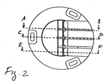
- Figures 2 and 2a to 2c show the upper housing part 11 in several cross-sectional representations.
- Figure 2 shows the Position of the sectional representations from FIGS. 2a to 2c.
- Figure 2a which is the cross section of Figure 2 in the direction A-C shows how the inclined surface 30 to the horizontal surface 32 is angled at the top.
- the sloping surface goes up to the outer edge 13 of the upper housing part 11 that also connects the vertical side surface 12.
- shown is also the light source and its energy supply receiving cavity 5 with associated light source recess 51.
- a power cable feed is from the bottom 14 of the housing body possible.
- FIG. 2 b shows a cross section in the direction E-F from FIG. 2.
- the recess 51 for the light source there is also the recess 52 visible for the window 7.
- the window recess Immediately to the Partial light channel 2 joins the window recess, through which the light L coupled out from the window 7 is guided will ( Figure 3).
- the free area 21 of the partial light channel 2 is a sloping towards the outer edge 13 of the housing body 11 Slant (only a few degrees, therefore not shown).
- FIG. 2c shows a cross section in the direction C-D from FIG. 2, a cross section through the fastening recesses 4 with screw passage 41 is visible.
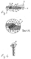
- Figure 3 shows a sectional view through the area of Light source 6 in the cavity 5 and 51 and the window 7 in its recess 52 and the partial light channel 2 through which the emitted light L is guided.
- the mounted light source is in the form of a light emitting diode 6.
- the window 7 is designed as a prism, the light entry surface 72 is not parallel to the light exit surface 71. hereby the light L is directed in the desired direction and it is also achieved that by adjusting the light exit surface 71 the desired dirt drainage to the vertical he follows.
- the light entry surface 72 is essentially oriented perpendicular to the direction of radiation of the light source 6, which enables optimal light coupling into window 7. See also detailed representation K.
- Figure 4 finally shows the systems arranged side by side 8 of light source (three LEDs 6 each) and Window 7.
Landscapes
- Engineering & Computer Science (AREA)
- Physics & Mathematics (AREA)
- Acoustics & Sound (AREA)
- Mechanical Engineering (AREA)
- Aviation & Aerospace Engineering (AREA)
- Architecture (AREA)
- Civil Engineering (AREA)
- Structural Engineering (AREA)
- General Engineering & Computer Science (AREA)
- Non-Portable Lighting Devices Or Systems Thereof (AREA)
Abstract
Description
- Figur 1
- eine Aufsicht mit zwei Detailausschnitten auf eine erfindungsgemäßen Unterflurleuchte mit vier Teillichtkanälen,
- Figur 1a und 1b
- Detailbilder aus Figur 1,
- Figur 2
- eine Aufsicht auf die Unterflurleuchte aus Figur 1, wobei die Schnitte gemäß Figur 3a bis 3c gekennzeichnet sind,
- Figur 2a
- Schnitt in Richtung AB durch die Unterflurleuchte aus Figur 3, wobei der Schnitt durch den Steg verläuft,
- Figur 2b
- Schnitt in Richtung EF aus Figur 3, wobei der Schnitt durch den Lichtkanal erfolgt, wobei das Fenster nicht eingesetzt ist,
- Figur 2c
- Schnitt in Richtung CD durch den Unterflurleuchte aus Figur 3, wobei der Schnitt unter anderem durch die Verschraubungsausnehmung 4 verläuft,
- Figur 3
- eine Detailschnittdarstellung durch den Borsteinreflektor mit darin befindlichen Lichtquellefenster und Lichtkanal, wobei das Detail K herausgestellt vergrößert ist, und
- Figur 4
- eine Anordnung der nebeneinanderliegenden Systeme, welche jeweils aus drei Lichtquellen und zugehörigem Fenster bestehen.
- 1
- Unterflurleuchte
- 11
- Oberteil
- 12
- Seitenfläche
- 13
- äußerer Rand
- 14
- Unterseite (Montageseite)
- 15
- Oberseite
- 2
- Teil-Lichtkanal
- 21
- Freifläche
- 30
- Schrägfläche
- 301
- Rille
- 31
- Steg
- 32
- Horizontalfläche
- 321
- Pyramiden
- 4
- Ausnehmung
- 41
- Durchführungs-Bohrung
- 5
- Hohlraum
- 51
- Lichtquellenaussparung
- 52
- Durchbruch
- 53
- äußerer Rand
- 54
- Randfläche
- 6
- Leuchtdiode, Lichtquelle
- 61
- Platine
- L
- emittiertes Licht
- 7
- Prisma
- 71
- Lichtaustrittsfläche
- 72
- Lichteintrittsfläche
- 73
- unterer Rand
- 8
- System (Lichtquelle und Fenster)
- H
- Horizontale
Claims (9)
- Unterflurleuchte (1) mit einem aus Oberteil (11) und Unterteil gebildeten Gehäuse zur Aufnahme einer lichtdurchlässigen Abdeckung (7) sowie einer im Oberteil (11) angeordneten Lichtquelle (6) und/oder einer lichtführenden Optik, wobei die lichtdurchlässige Abdeckung (7) ein im Oberteil (11) eingesetztes Prisma (7) aufweist, aus dem das Lichtbündel (2) in einer bestimmten Richtung, insbesondere in einem engen, spitzen Winkelbereich zur Horizontalen (H) austritt, und das Prisma (7) gegenüber dem eintretenden Licht eine hierzu senkrechte Eintrittsfläche (72) und gegenüber dem austretenden Licht eine schräggerichtete Austrittsfläche (71) aufweist,
dadurch gekennzeichnet, dass in dem Oberteil (11) eine im wesentlichen horizontale, d.h. gegenüber der Horizontalen allenfalls geringfügig abwärtsgeneigte, und gegenüber der Oberseite (15) des Oberteiles (11) abgesetzte Freifläche (21) ausgebildet ist, die sich an den unteren Rand (73) der Austrittsfläche (71) des Prismas (7) anschließt und sich bis an den äußeren Rand (13) des Oberteils (11) erstreckt, und das Prisma (7) zwischen dem Rand (13) der Freifläche (21) und der Oberseite (15) dergestalt schräg eingesetzt ist, dass die Austrittsfläche (71) des Prismas (7) gegenüber der Horizontalen (H) einen Winkel von etwa 135° bildet. - Unterflurleuchte nach Anspruch 1,
dadurch gekennzeichnet, dass das Prisma (7) in einem im Oberteil (11) des Gehäuses ausgebildeten Durchbruch (52) eingesetzt ist. - Unterflurleuchte nach Anspruch 1 oder 2,
dadurch gekennzeichnet, dass die Lichtquelle (6) und/oder die lichtführende Optik ebenfalls in dem Durchbruch (52) im Oberteil (11) des Gehäuses untergebracht ist. - Unterflurleuchte nach einem der Ansprüche 1 bis 3,
dadurch gekennzeichnet, dass die Freifläche (21) von zumindest einem Steg (31) unterbrochen ist, welcher Steg (31) sich von der Oberseite (15) des Gehäuseoberteiles (11) in sektionaler Richtung schräg abwärtsgeneigt bis zum äußeren Rand (13) des Gehäuseoberteiles (11) erstreckt. - Unterflurleuchte nach Anspruch 4,
dadurch gekennzeichnet, dass der wenigstens eine Steg (31) die Freifläche zur Ausbildung von Teil-Lichtkanälen (2) unterteilt. - Unterflurleuchte nach einem der Ansprüche 1 bis 5,
dadurch gekennzeichnet, dass das Gehäuseoberteil (11) an seiner Oberseite (15) außerhalb der Freifläche (21) noch im wesentlichen zwei gegeneinander geneigte Flächen aufweist, nämlich eine relativ zum Oberteil (11) etwa mittige Horizontalfläche (32) und eine hieran außermittig anschließende, radial nach außen abwärtsgeneigte Schrägfläche (30), wobei die Freifläche (21) sowohl einen Teil der Horizontalfläche (32) als auch einen Teil der Schrägfläche (31) herausschneidet. - Unterflurleuchte nach Anspruch 6,
dadurch gekennzeichnet, dass die Freifläche (21) im wesentlichen glatt ausgebildet ist, während die Horizontal- und/oder Schrägfläche (30, 32) strukturiert ist. - Unterflurleuchte nach einem der Ansprüche 1 bis 7,
dadurch gekennzeichnet, dass das Gehäuseoberteil (11) einstückig ausgebildet ist. - Unterflurleuchte nach einem der Ansprüche 1 bis 8,
dadurch gekennzeichnet, dass mehrere, nämlich wenigstens zwei Prismen (7) räumlich nebeneinander angeordnet sind, wobei die Lichtausstrahlung von den Prismen (7) im wesentlichen in die gleiche Richtung in den von der Freifläche (21) definierten Lichtkanal (2) erfolgt.
Applications Claiming Priority (2)
| Application Number | Priority Date | Filing Date | Title |
|---|---|---|---|
| DE20202407U | 2002-02-15 | ||
| DE20202407U DE20202407U1 (de) | 2002-02-15 | 2002-02-15 | Unterflurleuchte |
Publications (2)
| Publication Number | Publication Date |
|---|---|
| EP1344867A2 true EP1344867A2 (de) | 2003-09-17 |
| EP1344867A3 EP1344867A3 (de) | 2005-10-26 |
Family
ID=7967870
Family Applications (1)
| Application Number | Title | Priority Date | Filing Date |
|---|---|---|---|
| EP03003334A Withdrawn EP1344867A3 (de) | 2002-02-15 | 2003-02-13 | Unterflurleuchte |
Country Status (3)
| Country | Link |
|---|---|
| EP (1) | EP1344867A3 (de) |
| AT (1) | AT7277U1 (de) |
| DE (1) | DE20202407U1 (de) |
Families Citing this family (4)
| Publication number | Priority date | Publication date | Assignee | Title |
|---|---|---|---|---|
| AT413560B (de) * | 2001-09-26 | 2006-03-15 | Swarco Futurit Verkehrssignals | Fahrbahn-markierungsleuchte |
| EP1367179A1 (de) * | 2002-05-27 | 2003-12-03 | Gifas Electric Gesellschaft m.b.H. | Leuchteinheit |
| DE10246144A1 (de) * | 2002-10-01 | 2004-04-15 | Garufo Gmbh | Bodenmarkierungsleuchte |
| DE102006057071B3 (de) * | 2006-11-29 | 2008-04-10 | Sven Quitschau | Mineralisches Bauelement mit integriertem Leuchtmittel, Verfahren zu dessen Herstellung und Leuchtmittel |
Citations (3)
| Publication number | Priority date | Publication date | Assignee | Title |
|---|---|---|---|---|
| DE29712281U1 (de) | 1996-05-23 | 1997-12-04 | Siemens AG, 80333 München | Leuchteinrichtung zur Signalabgabe, Kennzeichnung oder Markierung |
| DE29723372U1 (de) | 1996-05-23 | 1998-08-13 | Siemens AG, 80333 München | Leuchteinrichtung für Flughäfen, insbesondere Unterflurfeuer |
| DE19809253A1 (de) | 1998-03-05 | 1999-09-09 | Aqua Signal Ag | Unterflurleuchte und Gruppe von Unterflurleuchten |
Family Cites Families (3)
| Publication number | Priority date | Publication date | Assignee | Title |
|---|---|---|---|---|
| CH672830A5 (de) * | 1987-03-16 | 1989-12-29 | Meta Fer Ag | |
| DE4008932A1 (de) * | 1990-03-20 | 1991-09-26 | Siemens Ag | Modular aufgebautes beleuchtungssystem, insbesondere fuer fahr- und rollbahnen von flughaefen |
| JP3931414B2 (ja) * | 1997-10-31 | 2007-06-13 | 東芝ライテック株式会社 | 埋込型標識灯および埋込型標識灯装置 |
-
2002
- 2002-02-15 DE DE20202407U patent/DE20202407U1/de not_active Expired - Lifetime
-
2003
- 2003-02-13 EP EP03003334A patent/EP1344867A3/de not_active Withdrawn
- 2003-03-28 AT AT0021703U patent/AT7277U1/de not_active IP Right Cessation
Patent Citations (3)
| Publication number | Priority date | Publication date | Assignee | Title |
|---|---|---|---|---|
| DE29712281U1 (de) | 1996-05-23 | 1997-12-04 | Siemens AG, 80333 München | Leuchteinrichtung zur Signalabgabe, Kennzeichnung oder Markierung |
| DE29723372U1 (de) | 1996-05-23 | 1998-08-13 | Siemens AG, 80333 München | Leuchteinrichtung für Flughäfen, insbesondere Unterflurfeuer |
| DE19809253A1 (de) | 1998-03-05 | 1999-09-09 | Aqua Signal Ag | Unterflurleuchte und Gruppe von Unterflurleuchten |
Also Published As
| Publication number | Publication date |
|---|---|
| DE20202407U1 (de) | 2002-05-16 |
| AT7277U1 (de) | 2004-12-27 |
| EP1344867A3 (de) | 2005-10-26 |
Similar Documents
| Publication | Publication Date | Title |
|---|---|---|
| DE69108915T2 (de) | Rollbahnleuchte. | |
| EP3334864B1 (de) | Längliche spanneinheit | |
| EP1918480B1 (de) | Handlauf mit darin befindlichen elektrischen Lichtquellen | |
| DE19851174B4 (de) | Signalleuchte, insbesondere Heckleuchte, von Fahrzeugen, vorzugsweise von Kraftfahrzeugen | |
| EP3211297A1 (de) | Leuchtenmodul insbesondere für strassenleuchten | |
| EP1344867A2 (de) | Unterflurleuchte | |
| AT413560B (de) | Fahrbahn-markierungsleuchte | |
| DE20312518U1 (de) | Fahrzeugleuchte | |
| WO2024227696A1 (de) | Schrankenbaum für eine schrankenanlage | |
| EP4036353B1 (de) | Zaunsystem mit indirekter beleuchtung | |
| DE19738297A1 (de) | Leuchtbauteil für Straßenbau und Architektur sowie zugehöriges Leuchtelement | |
| EP2295851A2 (de) | Lichtbeeinflussungselement | |
| EP2902699B1 (de) | Lichteinheit für laternenförmige Leuchte | |
| EP2927889B1 (de) | Signalgeber zur abgabe eines lichtsignals | |
| DE102010014210A1 (de) | Linienförmige LED-Leuchte, insbesondere LED-Ringleuchte | |
| EP1657209A1 (de) | Fahrtreppe oder Fahrsteig | |
| DE3437821A1 (de) | Leuchtende leitvorrichtung fuer strassenbeleuchtung | |
| DE19834195A1 (de) | Außenleuchte | |
| DE8815598U1 (de) | Lichtleiste | |
| DE102006021963A1 (de) | Leuchte, insbesondere Heckleuchte | |
| EP0518233A1 (de) | Leiteinrichtung | |
| EP1693332B1 (de) | Beförderungsanlage mit einer Linsenanordnung zur Integration in eine Wandung, Verfahren zur Montage der Beförderungsanlage | |
| DE2615107A1 (de) | Strassenleuchte, insbesondere mittelstreifenleuchte, fuer richtungsfahrbahnen | |
| EP1463651B1 (de) | Fahrzeugleuchte mit kreuzförmiger lichtverteilung | |
| EP4033142A1 (de) | Modulare tunnelbeleuchtungseinheit |
Legal Events
| Date | Code | Title | Description |
|---|---|---|---|
| PUAI | Public reference made under article 153(3) epc to a published international application that has entered the european phase |
Free format text: ORIGINAL CODE: 0009012 |
|
| AK | Designated contracting states |
Kind code of ref document: A2 Designated state(s): AT BE BG CH CY CZ DE DK EE ES FI FR GB GR HU IE IT LI LU MC NL PT SE SI SK TR |
|
| AX | Request for extension of the european patent |
Extension state: AL LT LV MK RO |
|
| PUAL | Search report despatched |
Free format text: ORIGINAL CODE: 0009013 |
|
| AK | Designated contracting states |
Kind code of ref document: A3 Designated state(s): AT BE BG CH CY CZ DE DK EE ES FI FR GB GR HU IE IT LI LU MC NL PT SE SI SK TR |
|
| AX | Request for extension of the european patent |
Extension state: AL LT LV MK RO |
|
| AKX | Designation fees paid | ||
| STAA | Information on the status of an ep patent application or granted ep patent |
Free format text: STATUS: THE APPLICATION IS DEEMED TO BE WITHDRAWN |
|
| 18D | Application deemed to be withdrawn |
Effective date: 20060427 |
|
| REG | Reference to a national code |
Ref country code: DE Ref legal event code: 8566 |