EP1344916B1 - Système d'alimentation en carburant - Google Patents
Système d'alimentation en carburant Download PDFInfo
- Publication number
- EP1344916B1 EP1344916B1 EP03251553A EP03251553A EP1344916B1 EP 1344916 B1 EP1344916 B1 EP 1344916B1 EP 03251553 A EP03251553 A EP 03251553A EP 03251553 A EP03251553 A EP 03251553A EP 1344916 B1 EP1344916 B1 EP 1344916B1
- Authority
- EP
- European Patent Office
- Prior art keywords
- valve
- pressure
- fuel
- main
- flow
- Prior art date
- Legal status (The legal status is an assumption and is not a legal conclusion. Google has not performed a legal analysis and makes no representation as to the accuracy of the status listed.)
- Expired - Lifetime
Links
- 239000000446 fuel Substances 0.000 title claims description 82
- 238000011144 upstream manufacturing Methods 0.000 claims description 12
- 238000000429 assembly Methods 0.000 description 4
- 230000037452 priming Effects 0.000 description 3
- 230000000694 effects Effects 0.000 description 2
- 230000002301 combined effect Effects 0.000 description 1
- 230000006835 compression Effects 0.000 description 1
- 238000007906 compression Methods 0.000 description 1
- 238000006073 displacement reaction Methods 0.000 description 1
- 230000001747 exhibiting effect Effects 0.000 description 1
- 239000002828 fuel tank Substances 0.000 description 1
- 230000006870 function Effects 0.000 description 1
- 230000000977 initiatory effect Effects 0.000 description 1
- 230000008707 rearrangement Effects 0.000 description 1
Images

Classifications
-
- F—MECHANICAL ENGINEERING; LIGHTING; HEATING; WEAPONS; BLASTING
- F02—COMBUSTION ENGINES; HOT-GAS OR COMBUSTION-PRODUCT ENGINE PLANTS
- F02C—GAS-TURBINE PLANTS; AIR INTAKES FOR JET-PROPULSION PLANTS; CONTROLLING FUEL SUPPLY IN AIR-BREATHING JET-PROPULSION PLANTS
- F02C9/00—Controlling gas-turbine plants; Controlling fuel supply in air- breathing jet-propulsion plants
- F02C9/26—Control of fuel supply
- F02C9/263—Control of fuel supply by means of fuel metering valves
-
- F—MECHANICAL ENGINEERING; LIGHTING; HEATING; WEAPONS; BLASTING
- F02—COMBUSTION ENGINES; HOT-GAS OR COMBUSTION-PRODUCT ENGINE PLANTS
- F02C—GAS-TURBINE PLANTS; AIR INTAKES FOR JET-PROPULSION PLANTS; CONTROLLING FUEL SUPPLY IN AIR-BREATHING JET-PROPULSION PLANTS
- F02C7/00—Features, components parts, details or accessories, not provided for in, or of interest apart form groups F02C1/00 - F02C6/00; Air intakes for jet-propulsion plants
- F02C7/22—Fuel supply systems
- F02C7/228—Dividing fuel between various burners
-
- F—MECHANICAL ENGINEERING; LIGHTING; HEATING; WEAPONS; BLASTING
- F02—COMBUSTION ENGINES; HOT-GAS OR COMBUSTION-PRODUCT ENGINE PLANTS
- F02C—GAS-TURBINE PLANTS; AIR INTAKES FOR JET-PROPULSION PLANTS; CONTROLLING FUEL SUPPLY IN AIR-BREATHING JET-PROPULSION PLANTS
- F02C9/00—Controlling gas-turbine plants; Controlling fuel supply in air- breathing jet-propulsion plants
- F02C9/26—Control of fuel supply
- F02C9/32—Control of fuel supply characterised by throttling of fuel
- F02C9/34—Joint control of separate flows to main and auxiliary burners
Definitions
- This invention relates to a fuel system for a gas turbine engine.
- a gas turbine engine it is known for a gas turbine engine to have two independently controlled sets of burners each set containing a plurality of burners, the two sets may be main burners and pilot burners.
- the pilot burners are arranged in parallel to receive the fuel from a pilot burner manifold, and one or more groups of main burners, the burners of each group receiving fuel from a respective main burner manifold.
- PRV Pressure Raising Valve
- the PRV receives a reference pressure against which it controls the pressure in the flow line to the pilot burners.
- the reference pressure for the PRV is the low pressure fuel supply to the fuel system.
- main and pilot burners their flow numbers may well be such that with all valves fully open 70% of the fuel would flow through the main burners and 30% of the fuel would flow through the pilot burners.
- the main and pilot burners would then be said to exhibit a 70/30 flow split. It can be shown (as will be explained in more detail hereinafter) that in a conventional system having a ratio of main/pilot burner flow numbers of 70:30, although the flow of fuel through the burners can be varied to control both the total fuel supplied to the burners and the split of that total fuel flow between the main and pilot burners, a main/pilot flow split in excess of 70/30 cannot be achieved. It is an object of the present invention to provide a fuel system wherein the control mechanism can achieve a main/pilot flow split exceeding the main/pilot burner flow number ratio.
- a fuel system for a gas turbine engine having a main burner fuel supply line and a pilot burner fuel supply line, a high pressure pump supplying fuel to the main and pilot burner supply lines in use, a throttle valve controlling the flow of fuel in the main burner supply line, a metering valve controlling the flow of fuel in the pilot burner supply line, and a pressure raising valve between the pilot burners and the metering valve, the pressure raising valve serving to maintain the system fuel pressure upstream of the pressure raising valve to a pre-determined amount in excess of the pressure of fuel supplied from the throttle valve to the main burners.
- said pressure raising valve has a movable valve member exposed to fuel pressure in a reference chamber of the valve, and said reference chamber is connected in use to a fuel line from said throttle valve to said main burners whereby the pressure in said reference chamber is the pressure of fuel supplied from said throttle valve to said main burners.
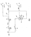
- the fuel system includes a pilot burner assembly 11 and a main burner assembly 12, the burners being part of a gas turbine engine, and the main burner assembly being divided into sub-assemblies 12a, 12b respectively.
- Fuel is supplied to the burners from a fuel tank or reservoir through the fuel control system.
- a low pressure (LP) pump 13 draws fuel from the reservoir and supplies it at low pressure through a filter 14 to the inlet of a high pressure pump 15.
- the high pressure pump 15 is a gear pump driven from a gearbox of the gas turbine engine and its speed varies with engine speed. As is well known with systems of this type the pump is sized so that it always provides a fuel flow in excess of the flow required by the engine.
- a pressure relief valve 17 in a return line 16 acts to protect the line 18 from excess pressure.
- the main output line 18 from the pump 15 contains a flow wash filter 19 and the line 18 supplies fuel under high pressure to a fuel shut off valve 21 which is open during normal operation of the fuel system and which divides the flow into a main burner flow line 22 and a pilot burner flow line 23.
- the pilot flow line 23 supplies fuel to a metering valve 24 for controlling the volume of fuel flowing to the pilot burners 11.
- the metering valve 24 supplies fuel to a pilot burner manifold 25 through a pressure raising valve 26.
- the operation of the metering valve is conventional, being controlled by a torque motor servo valve 27, the metering valve incorporating a linear variable displacement transducer (LVDT) to provide a valve position feedback signal to the electronic controller of the system such that the actual position of the control spool of the metering valve 24 can be verified in relation to the intended position set by operation of the servo valve 27.
- LVDT linear variable displacement transducer
- a combined pressure drop regulator and spill valve 28 has an inlet connected to the high pressure line 18 and can be operated to spill fuel from the line 18 back to the low pressure side of the pump 15 to maintain the pressure drop across the metering valve 24 at a pre-determined value, for example 0.483 MPa (70 psi). Any error in the pressure drop across the metering valve causing the spill valve 28 to move to vary the amount of fuel spilled from the line 18 back to the low pressure side of the pump 18 to correct the pressure drop across the valve 24. Ensuring that the pressure drop across the metering valve 24 remains constant ensures that the flow of fuel to the pilot burner manifold 25 is purely a function of the setting of the metering valve 24.
- the main burner flow line 22 supplies fuel through a flow sensing valve 31 to a main throttle valve 32.
- the flow sensing valve 31 measures the quantity of fuel flowing to the main burners of the engine and supplies a signal representative of the main burner flow to the electronic controller of the system.
- a similar signal is derived from the LVDT of the pilot metering valve 24 and the electronic controller can thus compute the total fuel flow to the engine burners, a quantity which is normally referred to as the "total burnt flow".
- the electronic controller can compute the ratio in which the total burnt flow is split between the main and pilot burners.
- the controller uses the total burnt flow as a measure of engine thrust, and controls the total burnt flow in accordance with the thrust demand set by the throttle controls of the engine.
- the split of fuel burnt between the main and pilot burners is controlled in accordance with Rules stored in the memory of the controller in relation to minimising emissions, for example during an aircraft take-off phase.
- a throttle servo valve 33 effects control over the position of the spool of the throttle valve 32, and thus controls the setting of the throttle valve 32 and the quantity of fuel supplied to the main burners.
- FIG. 1 shows sub-assemblies 12a and 12b as the main burners, and it can be seen that the throttle valve 32 supplies the burner assembly 12a directly, but supplies the burner assembly 12b through a shut-off valve 34.
- the valve 34 may be opened, and thus the flow from the throttle valve 32 will be divided between the main burner sub-assemblies 12a and 12b in accordance with their flow numbers. In the case where the flow numbers of the two sub-assemblies are the same the flow from the throttle valve 32 will be divided equally between the two sets of main burners 12a, 12b.
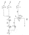
- main burners as a single main burner
- pilot burners as a single pilot burner
- the main burner having in this example a flow number of 70
- the pilot burner having a flow number of 30.
- the pressure raising valve 26 in the supply to the pilot burners has a movable valve member 26b which is exposed on one side to pressure in a reference pressure chamber 26a of the valve and has its opposite face exposed to pressure in a main pressure chamber 26c.
- a compression spring acts on the valve member 26b to assist the pressure in the chamber 26a in urging the member 26b towards a valve closed position.
- the valve 26 will be closed at engine start-up and will open when the pressure in the line 24a from the metering valve 24 to the chamber 26c of the pressure raising valve 26 exceeds a pre-determined value (the combined effect of the pressure in chamber 26a and the spring).
- the pressure raising valve 26 thus sets a minimum system pressure in the pilot burner line which must be exceeded before fuel flows to the pilot burners.
- the pressure at which the pressure raising valve 26 is operative is controlled by the pressure at the outlet of the LP pump 13 by a connection between the LP pump and chamber 26a. It is found however that such an arrangement has the effect that the fuel flow split between the main and pilot burners can never be set in excess of the ratio of the fuel flow number of the main burners to the fuel flow number of the pilot burners.
- the reference pressure supplied to the reference pressure chamber 26a of the pressure raising valve 26 is selected to be the pressure in the outlet line 32a from the throttle valve 32 of the main burners.
- the reference pressure for the valve 26 is derived through the lines 35 and 36 from the outlet of the throttle valve 32.
- the main/pilot burner flow split can be varied beyond the ratio of the flow numbers of the main and pilot burners.
- the flow numbers (the total flow areas) of the main and pilot burners may be split in the ratio 70/30, because the reference pressure for the pressure raising valve 26 is main burner manifold pressure, it is possible to achieve a 90/10 main/pilot burner flow split.
- the flow through the pilot burners is 4090 lph (900gph) and the flow number of the pilot burners is 30.
- the pressure P BP upstream of the pilot burners must be 10.35 MPa (1500psi).
- the pressure Pxp upstream of the pressure raising valve 26 is 10.5 MPa (1520.25psi) (the flow through the valve 26 being 4090 lph (900gph) and its flow number being 200).
- valve 26 will be wide open, and therefore exhibiting a flow number of 200, since the pressure PXP is in excess of 10.3 MPa (1500psi), and the reference pressure from the LP pump will be around 0.68 MPa (100psi) thus giving a very significant pressure differential and ensuring that the valve 26 is fully open.
- P BP the pilot manifold pressure upstream of the pilot burners
- P BM upstream of the main burners
- the pressure raising valve is set to ensure that the pressure P XP upstream of the pressure raising valve 26 is at least 1.38 MPa (200psi) in excess of the reference pressure for the valve 26.
- the reference pressure is P BM
- P XP will have a value of at least 15.8 MPa (2288psi).
- the pressure upstream of the valve 26 is set to be at least 1.38 MPa (200psi) above the pressure in the main burner manifold, the valve 26 remaining active (rather than being against its fully open stop). In this situation therefore the pressure H P at the outlet of the gear pump is high and there is always sufficient pressure drop across the main throttle valve 32 to ensure that the valve 32 can be operated to control the flow split between the main and pilot burners.
- Figure 1 illustrates a main burner situation in which the main burner flow is divided, during normal operation, between two sets 12a and 12b of main burners.
- the burners of the main burner set 12b are supplied with fuel through a Shut-Off Valve 34.
- the Shut-Off Valve 34 is controlled by a solenoid 38 which determines whether the valve 34 is open or closed, and thus whether fuel is supplied to the burners 12b, or not.
- the rate of opening of the valve 34 is controlled by the pressure drop across the valve 34 and across a fixed orifice (not shown) positioned between the valve 34 and a control pressure input of the solenoid 38.
- the porting of the valve 34 is arranged to minimise any dip in the flow to the burners 12a when the valve 34 opens.
- the valve 34 has a port which permits a small flow to the burners 12b to prime the burners 12b and this, together with a high pressure drop across the main ports of the valve 34 serves to limit the dip in flow to the burners 12a which occurs when the valve 34 opens to supply fuel to the burners 12b.
- the valve 34 is moved to an open position the initial effect is to supply a priming flow through the priming port, and also to use the flow displaced by the piston of the valve 34 in it open movement, to prime the burners 12b.
- the valve 34 travels to its fully opened position in which it produces a negligible flow restriction whereby the split between the burners 12a and 12b is parity.
- both sets of burners 12, 12b are primed with fuel at LP pump pressure while the engine is operating even when one or more of the main burners are deselected, and thus are not "burning".
- the priming with low pressure fuel enables a rapid ignition of the main stages of the burners when necessary since there is no requirement to prime the main burner system each time a main burner is to be selected.
- ports in its control sleeve feed low pressure fuel to the manifold of the burners 12a to keep that manifold primed.
- ports in the valve 34 prime the manifold 12b with low pressure fuel when the valve 34 is closed.
- Check valves located at the head of the injector stem of each burner prevent leakage to the burners so that the low pressure fuel in the manifold is maintained in the manifold and does not leak through the burners. When the manifolds are supplied with high pressure fuel the check valves open.
- valve 21 During normal operation when the valve 21 is open the switching ports connect the line 35 to the line 36 so that the reference chamber of the valve 26 sees the pressure in the main burner manifold. However, when the system is in "shut-down" mode the valve 21 closes the port connecting the line 35 to the line 36 and immediately thereafter connects the line 36 to the high pressure line 18 thereby driving the valve 26 to a closed condition and cutting off the fuel flow to the pilot burners 11. This ensures that the valve 26 remains closed even though-the engine may be windmilling.
Landscapes
- Engineering & Computer Science (AREA)
- Chemical & Material Sciences (AREA)
- Combustion & Propulsion (AREA)
- Mechanical Engineering (AREA)
- General Engineering & Computer Science (AREA)
- Feeding And Controlling Fuel (AREA)
Claims (2)
- Système d'alimentation en carburant pour une turbine à gaz, comportant une conduite d'alimentation en carburant du brûleur principal (32a) et une conduite d'alimentation en carburant du brûleur pilote (23, 24, 26, 25), une pompe haute pression (15) amenant en service le carburant vers les conduites d'alimentation des brûleurs principaux et pilotes, une soupape d'étranglement (32) contrôlant l'écoulement du carburant dans la conduite d'alimentation du brûleur principal (32a), une soupape de dosage (24) contrôlant l'écoulement du carburant dans la conduite d'alimentation du brûleur pilote et une soupape d'accroissement de la pression (26) entre les brûleurs pilotes (11) et la soupape de dosage (24), le système étant caractérisé en ce que la soupape d'accroissement de la pression (26) sert à maintenir la pression de carburant du système en amont de la soupape d'accroissement de la pression (26) à une valeur dépassant d'une valeur prédéterminée la pression du carburant amené par la soupape d'étranglement (32) vers les brûleurs principaux (12a, 12b).
- Système d'alimentation en carburant selon la revendication 1, caractérisé en ce que ladite soupape d'accroissement de la pression (26) comporte un élément de soupape mobile (26b), exposé à la pression du carburant dans une chambre de référence (26a) de la soupape, ladite chambre de référence étant connectée en service à la conduite d'alimentation en carburant (32a) menant de ladite soupape d'étranglement (32) vers lesdits brûleurs principaux (12a, 12b), la pression dans ladite chambre de référence correspondant ainsi à la pression du carburant amené par ladite soupape d'étranglement vers lesdits brûleurs principaux.
Applications Claiming Priority (2)
| Application Number | Priority Date | Filing Date | Title |
|---|---|---|---|
| GB0206220 | 2002-03-15 | ||
| GBGB0206220.6A GB0206220D0 (en) | 2002-03-15 | 2002-03-15 | Fuel system |
Publications (3)
| Publication Number | Publication Date |
|---|---|
| EP1344916A2 EP1344916A2 (fr) | 2003-09-17 |
| EP1344916A3 EP1344916A3 (fr) | 2005-01-05 |
| EP1344916B1 true EP1344916B1 (fr) | 2006-12-13 |
Family
ID=9933097
Family Applications (1)
| Application Number | Title | Priority Date | Filing Date |
|---|---|---|---|
| EP03251553A Expired - Lifetime EP1344916B1 (fr) | 2002-03-15 | 2003-03-13 | Système d'alimentation en carburant |
Country Status (4)
| Country | Link |
|---|---|
| US (1) | US6813876B2 (fr) |
| EP (1) | EP1344916B1 (fr) |
| DE (1) | DE60310284T2 (fr) |
| GB (1) | GB0206220D0 (fr) |
Families Citing this family (38)
| Publication number | Priority date | Publication date | Assignee | Title |
|---|---|---|---|---|
| GB0216043D0 (en) * | 2002-07-11 | 2002-08-21 | Lucas Industries Ltd | Fuel system |
| US6981359B2 (en) * | 2003-06-16 | 2006-01-03 | Woodward Governor Company | Centrifugal pump fuel system and method for gas turbine engine |
| GB0401207D0 (en) * | 2004-01-21 | 2004-02-25 | Goodrich Control Sys Ltd | Fuel supply system |
| US7386981B2 (en) | 2004-03-31 | 2008-06-17 | Honeywell International Inc. | Method and apparatus generating multiple pressure signals in a fuel system |
| EP1735529B1 (fr) * | 2004-04-16 | 2016-05-11 | Honeywell International Inc. | Procédé et appareil permettant de générer plusieurs signaux de pression dans un système de combustible |
| US7360918B2 (en) * | 2005-02-28 | 2008-04-22 | Vince Trombetta | High-efficiency solar-charging LED window candle |
| US7726112B2 (en) * | 2006-04-24 | 2010-06-01 | Pratt & Whitney Canada Corp. | Fuel system of gas turbine engines |
| US7779811B1 (en) | 2006-09-13 | 2010-08-24 | General Electric Company | Thermoelectrically cooled components for distributed electronics control system for gas turbine engines |
| US7841184B2 (en) * | 2007-04-19 | 2010-11-30 | Pratt & Whitney Canada Corp. | Start flow measurement |
| US8128378B2 (en) * | 2007-07-30 | 2012-03-06 | Honeywell International Inc. | Dual mode compensation for variable displacement pump fluid metering system |
| DE102008032565A1 (de) | 2008-07-11 | 2010-01-14 | Rolls-Royce Deutschland Ltd & Co Kg | Brennstoffzufuhrsystem für ein Gasturbinentriebwerk |
| GB0820410D0 (en) * | 2008-11-07 | 2008-12-17 | Goodrich Control Sys Ltd | Engine relight method |
| US8572985B2 (en) * | 2009-06-26 | 2013-11-05 | Pratt & Whitney Canada Corp. | Air filtration system for gas turbine engine pneumatic system |
| US8776529B2 (en) * | 2010-09-27 | 2014-07-15 | Hamilton Sundstrand Corporation | Critical flow nozzle for controlling fuel distribution and burner stability |
| EP2469057B1 (fr) * | 2010-12-22 | 2013-11-13 | Rolls-Royce Engine Control Systems Ltd | Système de gradation de combustible |
| US20120167594A1 (en) * | 2011-01-05 | 2012-07-05 | Hamilton Sundstrand Corporation | Bypass Monitor for Fuel Supply System |
| CN103748338B (zh) * | 2011-08-19 | 2016-05-25 | 伍德沃德公司 | 分流控制装置 |
| GB201117160D0 (en) * | 2011-10-05 | 2011-11-16 | Rolls Royce Goodrich Engine Control Systems Ltd | Fuel system |
| US9068511B2 (en) | 2012-04-26 | 2015-06-30 | Hamilton Sundstrand Corporation | Pressure regulating valve |
| US8511329B1 (en) | 2012-04-26 | 2013-08-20 | Hamilton Sundstrand Corporation | Metering valve |
| US8950420B2 (en) | 2012-04-26 | 2015-02-10 | Hamilton Sundstrand Corporation | Containment housing for a fuel control housing |
| US8511330B1 (en) | 2012-04-26 | 2013-08-20 | Hamilton Sundstrand Corporation | Servo minimum pressure valve |
| US9103284B2 (en) * | 2012-05-31 | 2015-08-11 | General Electric Company | Utilization of fuel gas for purging a dormant fuel gas circuit |
| US20150226170A1 (en) * | 2014-02-12 | 2015-08-13 | Woodward, Inc. | Pressure Regulator Damping |
| JP6286580B2 (ja) * | 2014-03-31 | 2018-02-28 | シーメンス アクティエンゲゼルシャフト | ガスタービン設備のガス供給系のための圧力調整装置 |
| FR3027059B1 (fr) * | 2014-10-13 | 2019-08-30 | Safran Helicopter Engines | Systeme d'allumage d'une chambre de combustion d'un turbomoteur |
| EP3070408B1 (fr) | 2015-03-20 | 2018-06-06 | Rolls-Royce PLC | Système de combustion étagé |
| GB201603054D0 (en) | 2016-02-23 | 2016-04-06 | Rolls Royce Controls & Data Services Ltd | Combustion staging system |
| GB201604120D0 (en) * | 2016-03-10 | 2016-04-27 | Rolls Royce Controls & Data Services Ltd | Combustion staging system |
| GB201604651D0 (en) | 2016-03-18 | 2016-05-04 | Rolls Royce Controls & Data Services Ltd | Combustion staging system |
| US10203704B2 (en) * | 2016-06-16 | 2019-02-12 | Moog Inc. | Fluid metering valve |
| GB2557599B (en) * | 2016-12-09 | 2019-05-15 | Rolls Royce Plc | Gas turbine engine fuel supply system having de-priming and re-priming sub-systems |
| IT201700073686A1 (it) * | 2017-06-30 | 2018-12-30 | Nuovo Pignone Tecnologie Srl | Metodo e sistema per l'avvio sicuro di turbine a gas |
| US11994076B2 (en) * | 2021-03-31 | 2024-05-28 | Woodward, Inc. | Multi-step pressurizing valve system |
| US12270343B2 (en) * | 2022-08-26 | 2025-04-08 | Collins Engine Nozzles, Inc. | Proportional restriction of fuel nozzle with an auxiliary circuit |
| US11970976B2 (en) | 2022-08-26 | 2024-04-30 | Hamilton Sundstrand Corporation | Variable restriction of fuel nozzle with an auxiliary circuit |
| US12203419B2 (en) * | 2022-11-29 | 2025-01-21 | Woodward, Inc. | System and method for in situ verification of redundant electro-hydraulic servo valve (EHSV) operational status in redundant flow control systems |
| CN119878375B (zh) * | 2025-03-31 | 2025-05-30 | 中国科学院工程热物理研究所 | 一种航空发动机多燃烧室供油的燃油调节装置、方法及应用 |
Family Cites Families (6)
| Publication number | Priority date | Publication date | Assignee | Title |
|---|---|---|---|---|
| GB8903070D0 (en) * | 1989-02-10 | 1989-05-17 | Lucas Ind Plc | Fuel supply apparatus |
| US5339636A (en) * | 1992-12-04 | 1994-08-23 | United Technologies Corporation | Fuel splitter valve assembly for gas turbine |
| US5448882A (en) * | 1993-12-14 | 1995-09-12 | United Technologies Corporation | Fuel metering system |
| EP1045964B1 (fr) * | 1998-01-08 | 2012-08-08 | United Technologies Corporation | Systeme de pressurisation hydraulique a deux niveaux |
| GB0023727D0 (en) * | 2000-09-27 | 2000-11-08 | Lucas Industries Ltd | Control system |
| SE521293C2 (sv) * | 2001-02-06 | 2003-10-21 | Volvo Aero Corp | Förfarande och anordning för tillförsel av bränsle till en brännkammare |
-
2002
- 2002-03-15 GB GBGB0206220.6A patent/GB0206220D0/en not_active Ceased
-
2003
- 2003-03-13 EP EP03251553A patent/EP1344916B1/fr not_active Expired - Lifetime
- 2003-03-13 DE DE60310284T patent/DE60310284T2/de not_active Expired - Lifetime
- 2003-03-14 US US10/389,627 patent/US6813876B2/en not_active Expired - Lifetime
Also Published As
| Publication number | Publication date |
|---|---|
| US20040025492A1 (en) | 2004-02-12 |
| EP1344916A3 (fr) | 2005-01-05 |
| EP1344916A2 (fr) | 2003-09-17 |
| GB0206220D0 (en) | 2002-05-01 |
| US6813876B2 (en) | 2004-11-09 |
| DE60310284D1 (de) | 2007-01-25 |
| DE60310284T2 (de) | 2007-06-28 |
Similar Documents
| Publication | Publication Date | Title |
|---|---|---|
| EP1344916B1 (fr) | Système d'alimentation en carburant | |
| US8887752B2 (en) | Fuel staging system | |
| EP2497923B1 (fr) | Système de carburant | |
| US6655152B2 (en) | Fuel control system for multiple burners | |
| JP5666604B2 (ja) | 航空エンジンのための燃料供給回路 | |
| EP2417383B1 (fr) | Robinet de sectionnement à détection de débit | |
| EP4063633B1 (fr) | Système d'alimentation en carburant doté d'un compteur de mesure et d'une soupape d'arrêt d'urgence | |
| GB2285286A (en) | Fuel metering system | |
| US8499542B2 (en) | Flow balancing valve | |
| US6205766B1 (en) | Fluid flow valve and fluid flow system | |
| EP2469057A1 (fr) | Système de stratification de combustible | |
| EP0388046A2 (fr) | Système de commande de combustible d'un moteur à turbine à gaz et soupape de dosage | |
| EP1344917B1 (fr) | Système de régulation d'alimentation en carburant | |
| EP0227273B1 (fr) | Système de commande de carburant d'un moteur à turbine à gaz | |
| US3991569A (en) | Fuel control system for gas turbine engine | |
| GB2417051A (en) | Fuel control system for gas turbine engine re-heat system | |
| US4074521A (en) | Fuel control system for a gas turbine engine | |
| EP1355054A2 (fr) | Système de régulation de carburant pour une turbine à gaz avec protection contre surpoussée | |
| EP4141237B1 (fr) | Vanne de dosage avec arrêt à mi-course | |
| US4019317A (en) | Fluid flow control valve for gas turbine engine fuel control system | |
| EP4137691A1 (fr) | Orifices de dosage en série pour une soupape de dosage | |
| GB1423361A (en) | Priming valve arrangement for liquid fuel supply system | |
| CA1293131C (fr) | Commande d'alimentation en combustible, pour turbine a gaz | |
| US3957080A (en) | Priming valve for liquid fuel supply system | |
| RU2476702C2 (ru) | Система подачи топлива в газотурбинный двигатель |
Legal Events
| Date | Code | Title | Description |
|---|---|---|---|
| PUAI | Public reference made under article 153(3) epc to a published international application that has entered the european phase |
Free format text: ORIGINAL CODE: 0009012 |
|
| AK | Designated contracting states |
Kind code of ref document: A2 Designated state(s): AT BE BG CH CY CZ DE DK EE ES FI FR GB GR HU IE IT LI LU MC NL PT RO SE SI SK TR |
|
| AX | Request for extension of the european patent |
Extension state: AL LT LV MK |
|
| PUAL | Search report despatched |
Free format text: ORIGINAL CODE: 0009013 |
|
| AK | Designated contracting states |
Kind code of ref document: A3 Designated state(s): AT BE BG CH CY CZ DE DK EE ES FI FR GB GR HU IE IT LI LU MC NL PT RO SE SI SK TR |
|
| AX | Request for extension of the european patent |
Extension state: AL LT LV MK |
|
| 17P | Request for examination filed |
Effective date: 20050609 |
|
| AKX | Designation fees paid |
Designated state(s): DE ES FR GB IT |
|
| GRAP | Despatch of communication of intention to grant a patent |
Free format text: ORIGINAL CODE: EPIDOSNIGR1 |
|
| GRAS | Grant fee paid |
Free format text: ORIGINAL CODE: EPIDOSNIGR3 |
|
| GRAA | (expected) grant |
Free format text: ORIGINAL CODE: 0009210 |
|
| AK | Designated contracting states |
Kind code of ref document: B1 Designated state(s): DE ES FR GB IT |
|
| PG25 | Lapsed in a contracting state [announced via postgrant information from national office to epo] |
Ref country code: IT Free format text: LAPSE BECAUSE OF FAILURE TO SUBMIT A TRANSLATION OF THE DESCRIPTION OR TO PAY THE FEE WITHIN THE PRESCRIBED TIME-LIMIT;WARNING: LAPSES OF ITALIAN PATENTS WITH EFFECTIVE DATE BEFORE 2007 MAY HAVE OCCURRED AT ANY TIME BEFORE 2007. THE CORRECT EFFECTIVE DATE MAY BE DIFFERENT FROM THE ONE RECORDED. Effective date: 20061213 |
|
| REG | Reference to a national code |
Ref country code: GB Ref legal event code: FG4D |
|
| REF | Corresponds to: |
Ref document number: 60310284 Country of ref document: DE Date of ref document: 20070125 Kind code of ref document: P |
|
| PG25 | Lapsed in a contracting state [announced via postgrant information from national office to epo] |
Ref country code: ES Free format text: LAPSE BECAUSE OF FAILURE TO SUBMIT A TRANSLATION OF THE DESCRIPTION OR TO PAY THE FEE WITHIN THE PRESCRIBED TIME-LIMIT Effective date: 20070324 |
|
| ET | Fr: translation filed | ||
| PLBE | No opposition filed within time limit |
Free format text: ORIGINAL CODE: 0009261 |
|
| STAA | Information on the status of an ep patent application or granted ep patent |
Free format text: STATUS: NO OPPOSITION FILED WITHIN TIME LIMIT |
|
| 26N | No opposition filed |
Effective date: 20070914 |
|
| REG | Reference to a national code |
Ref country code: DE Ref legal event code: R081 Ref document number: 60310284 Country of ref document: DE Owner name: GOODRICH CONTROL SYSTEMS, GB Free format text: FORMER OWNER: GOODRICH CONTROL SYSTEMS LTD., LUTON, GB Effective date: 20140220 Ref country code: DE Ref legal event code: R081 Ref document number: 60310284 Country of ref document: DE Owner name: GOODRICH CONTROL SYSTEMS, SOLIHULL, GB Free format text: FORMER OWNER: GOODRICH CONTROL SYSTEMS LTD., LUTON, BEDFORDSHIRE, GB Effective date: 20140220 |
|
| REG | Reference to a national code |
Ref country code: FR Ref legal event code: CJ Effective date: 20140313 Ref country code: FR Ref legal event code: CD Owner name: GOODRICH CONTROL SYSTEMS Effective date: 20140313 |
|
| REG | Reference to a national code |
Ref country code: FR Ref legal event code: PLFP Year of fee payment: 14 |
|
| REG | Reference to a national code |
Ref country code: FR Ref legal event code: PLFP Year of fee payment: 15 |
|
| REG | Reference to a national code |
Ref country code: FR Ref legal event code: PLFP Year of fee payment: 16 |
|
| PGFP | Annual fee paid to national office [announced via postgrant information from national office to epo] |
Ref country code: GB Payment date: 20200221 Year of fee payment: 18 Ref country code: DE Payment date: 20200218 Year of fee payment: 18 |
|
| PGFP | Annual fee paid to national office [announced via postgrant information from national office to epo] |
Ref country code: FR Payment date: 20200220 Year of fee payment: 18 |
|
| REG | Reference to a national code |
Ref country code: DE Ref legal event code: R119 Ref document number: 60310284 Country of ref document: DE |
|
| GBPC | Gb: european patent ceased through non-payment of renewal fee |
Effective date: 20210313 |
|
| PG25 | Lapsed in a contracting state [announced via postgrant information from national office to epo] |
Ref country code: FR Free format text: LAPSE BECAUSE OF NON-PAYMENT OF DUE FEES Effective date: 20210331 Ref country code: GB Free format text: LAPSE BECAUSE OF NON-PAYMENT OF DUE FEES Effective date: 20210313 Ref country code: DE Free format text: LAPSE BECAUSE OF NON-PAYMENT OF DUE FEES Effective date: 20211001 |