EP1344928A2 - Tuyère à section variable - Google Patents
Tuyère à section variable Download PDFInfo
- Publication number
- EP1344928A2 EP1344928A2 EP03251019A EP03251019A EP1344928A2 EP 1344928 A2 EP1344928 A2 EP 1344928A2 EP 03251019 A EP03251019 A EP 03251019A EP 03251019 A EP03251019 A EP 03251019A EP 1344928 A2 EP1344928 A2 EP 1344928A2
- Authority
- EP
- European Patent Office
- Prior art keywords
- centre
- exhaust
- exit area
- core
- area
- Prior art date
- Legal status (The legal status is an assumption and is not a legal conclusion. Google has not performed a legal analysis and makes no representation as to the accuracy of the status listed.)
- Granted
Links
- 238000002156 mixing Methods 0.000 claims abstract description 12
- 230000003068 static effect Effects 0.000 claims description 11
- 239000007789 gas Substances 0.000 description 40
- 230000001141 propulsive effect Effects 0.000 description 7
- 239000003570 air Substances 0.000 description 6
- 230000009286 beneficial effect Effects 0.000 description 4
- 239000000446 fuel Substances 0.000 description 4
- 239000012080 ambient air Substances 0.000 description 2
- 239000012530 fluid Substances 0.000 description 2
- 238000002485 combustion reaction Methods 0.000 description 1
- 238000007599 discharging Methods 0.000 description 1
- 239000000203 mixture Substances 0.000 description 1
- 230000004048 modification Effects 0.000 description 1
- 238000012986 modification Methods 0.000 description 1
- 238000007789 sealing Methods 0.000 description 1
- 238000000926 separation method Methods 0.000 description 1
- 230000007704 transition Effects 0.000 description 1
- 238000011144 upstream manufacturing Methods 0.000 description 1
Images


Classifications
-
- F—MECHANICAL ENGINEERING; LIGHTING; HEATING; WEAPONS; BLASTING
- F02—COMBUSTION ENGINES; HOT-GAS OR COMBUSTION-PRODUCT ENGINE PLANTS
- F02K—JET-PROPULSION PLANTS
- F02K1/00—Plants characterised by the form or arrangement of the jet pipe or nozzle; Jet pipes or nozzles peculiar thereto
- F02K1/06—Varying effective area of jet pipe or nozzle
- F02K1/08—Varying effective area of jet pipe or nozzle by axially moving or transversely deforming an internal member, e.g. the exhaust cone
Definitions
- the present invention relates to a variable exhaust area nozzle for a gas turbine engine.
- An aircraft is required to perform many different operational modes in a single flight cycle. Such modes comprise taxiing, take-off, climb, cruise, holding, decent and landing to which the engines of the aircraft must also comply with related performance requirements.
- US 4,527,388 granted to The Garrett Corp. discloses a turbofan engine comprising a core engine and a fan bypass passage, both discharging streams of pressurised gases through a mixing section and into an exhaust nozzle.
- the exhaust nozzle defines a throat through which the combined gas streams are accelerated and discharged therethrough.
- the exhaust nozzle also comprises a single axially moveable and rearwardly tapering centre-body, which is moveable relative to the remainder of the exhaust nozzle to simultaneously vary both the throat area and one of the respective fluid flow areas through which the core engine and fan bypass passage fluid streams flow.
- the centre-body is translated rearward, for instance at takeoff, such that the areas of the exhaust nozzle and core are both minimum.
- a further object of the present invention is to provide a means for varying the aerodynamic profile of the exhaust nozzle such that; at high nozzle pressure ratios, for instance at cruise, the nozzle comprises a convergent-divergent profile; at lower nozzle pressure ratios, for instance aircraft take-off, decent or hold, the nozzle comprises a predominantly convergent profile.
- the present invention seeks to provide an exhaust nozzle assembly for a gas turbine engine, the assembly comprises a main axis, an inner nozzle, an outer nozzle, a translatable centre-body and a means for translating the centre-body between a forward position and a rearward position; the centre-body is disposed radially inwardly of the inner nozzle thereby partly defining an inner duct for a core engine gas flow, an outer duct for a bypass gas flow is defined by the inner nozzle and the outer nozzle, the outer nozzle extends downstream of the inner nozzle and with the centre-body defines a final mixing duct having a final exhaust exit area; wherein when the centre-body is in the forward position the final exhaust exit area is at a maximum area, and when the centre-body is in a rearward position the final exhaust exit area is at a minimum area.
- the inner nozzle defines a core exhaust exit area, and when the centre-body is in the forward position the core exhaust exit area is at a maximum area, and when the centre-body is in a rearward position the core exhaust exit area is at a minimum area.
- the inner nozzle defines a core exhaust exit area, and when the centre-body is in the forward position the core exhaust exit area is at a minimum area, and when the centre-body is in a rearward position the core exhaust exit area is at a maximum area.
- the centre-body and the outer nozzle define, in axial flow series, a converging portion and a diverging portion, the mixed exhaust flow then exits the final exhaust exit area which is at the minimum area.
- the centre-body comprises, in a downstream direction, a parallel portion, a waist, a diverging section, a maximum diameter portion and a taper; the parallel portion is substantially parallel and a part of which is slidably engaged with a static core engine structure.
- the waist when the centre-body is in the forward position the waist is generally axially aligned with the core exhaust exit area thereby providing the maximum core exhaust exit areas; when the centre-body is in the rearward position the parallel portion is axially aligned with core exhaust exit area thereby minimising the exit area.
- the centre-body comprises, in a downstream direction, a parallel portion, a diverging section, a maximum diameter portion and a taper; the parallel section is substantially parallel and a part of which is slidably engaged with a static core engine structure.
- the diverging section is generally axially aligned with core exhaust exit area thereby providing a constant core exhaust exit area.
- the waist is axially aligned with the core exhaust exit area thereby providing the maximum core exhaust exit areas; when the centre-body is in the rearward position the parallel portion is axially aligned with core exhaust exit area and thereby minimising the core exhaust exit area.
- the downstream end of the taper is generally axially aligned with the final exhaust exit area thereby providing the maximum final exit area; when the centre-body is in the rearward position the maximum diameter portion is generally axially aligned with the final exhaust exit area thereby minimising the final exit area.
- a means for translating the centre-body between a forward position and a rearward position comprises at least one actuator mounted within and to the static core engine structure, the actuator having a piston that is attached to a mounting on the translating centre-body.
- the engine when the centre-body is in the rearward position the engine is in high-speed mode and when the centre-body is in the forward position the engine is in low-speed mode.
- the centre-body is positioned between the forward position and the rearward position.
- a gas turbine engine comprising an exhaust nozzle assembly as claimed in any one of the preceding paragraphs.
- a ducted fan gas turbine engine 10 comprises, in axial flow series an air intake 12, a propulsive fan 14, a core engine 16 and an exhaust nozzle assembly 18 all disposed about a main engine axis 20.
- the exhaust nozzle assembly 18 comprises an outer nozzle 17 and a radially inner nozzle 19.
- the core engine 16 comprises, in axial flow series, a series of compressors 22, a combustor 24, and a series of turbines 26.
- the direction of airflow through the engine 10, in operation, is shown by arrow A and the terms upstream and downstream used throughout this description are used with reference to this general flow direction. Air is drawn in through the air intake 12 and is compressed and accelerated by the fan 14.
- the air from the fan 14 is split between a core engine flow 28 and a bypass flow 30.
- the core engine flow 28 enters core engine 16, flows through the core engine compressors 22 where it is further compressed, and into the combustor 24 where it is mixed with fuel, which is supplied to, and burnt within the combustor 24.
- Combustion of the fuel with the compressed air from the compressors 22 generates a high energy and velocity gas stream, which exits the combustor 24 and flows downstream through the turbines 26.
- As the high energy gas stream flows through the turbines 26 it rotates turbine rotors extracting energy from the gas stream which is used to drive the fan 14 and compressors 22 via engine shafts 32 which drivingly connect the turbines rotors with the compressors 22 and fan 14.
- the high energy gas stream from the combustor 24 still has a significant amount of energy and velocity and it is exhausted, as a core exhaust stream 28, through a core exhaust exit area 42 of the engine exhaust nozzle assembly 18 into a mixing area 36.
- the remainder of the air from, and accelerated by, the fan 14 flows within a bypass duct 34 around the core engine 16.
- the bypass flow 30 provides the majority of the useful propulsive thrust of the engine 10.
- a conventional flight cycle for a commercial aircraft comprises take-off, climb, cruise, descent and landing modes. If the aircraft is required to wait for a landing slot, then the flight cycle may also comprise a holding mode.
- the engine At take-off the engine is at full power and at near full power while the aircraft climbs to cruise altitude. During the cruise phase the engine operates at typically 70-80% of its full power. While the aircraft is descending the engines are reduced to 10-20% of full power.
- variable area nozzle providing the ability to control the working line and operating points of the engine's propulsive fan 14.
- the engine 10 is then able to operate at its maximum flow capacity at takeoff, reducing jet velocity, and consequently jet noise, for any given fan size and thrust level requirement.
- Variation of the core engine nozzle area 42 enables the core engine performance to be matched and adjusted in accordance with the exhaust jet velocity for the different flight cycle modes. This would enable the jet velocity profile to be optimised to achieve minimum specific fuel consumption at cruise and minimum jet noise at takeoff.
- the variable area exhaust nozzle assembly 18 of the present invention is suited to.
- a translating centre-body 44 is incorporated as part of the exhaust nozzle assembly 18.
- the centre-body 44 is disposed radially inwardly of the inner or core nozzle 19 thereby partly defining an inner or core duct 35 for the flow of core engine gas 28 therethrough.
- the inner nozzle 19 and the outer nozzle 17 define the outer or bypass duct 34 for the flow of bypass gas 30 therethrough.
- the outer nozzle 17 extends downstream of the inner nozzle 19 and with the centre-body 44 defines a final mixing duct/area 36. Both the core gas flow 28 and the bypass gas flow 30 discharge into the final mixing duct 36.
- the centre-body 44 is axially translatable and provides modification of the final exhaust exit area 38 between takeoff and cruise flight conditions.
- Figure 1 shows the centre-body 44 in a rearward position suitable for cruise flight of an associated aircraft.
- the final exhaust exit area 38 comprises a convergent-divergent profile that is beneficial for high nozzle pressure ratios, i.e. where there is a relatively large difference in exhaust gas and ambient pressures.
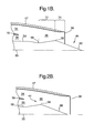
- Figure 2 shows the centre-body 44 in a forward position suitable for take-off or low air-speed of an associated aircraft. In this position the final exhaust exit area 38 comprises a convergent profile for relatively low nozzle pressure ratios.
- Figure 2 shows the sectional lines of the outer nozzle 17 and centre-body 44 diverging it should be appreciated that the cross-sectional area converges towards the final exhaust exit area 38.
- FIG. 3B which shows the nozzle assembly in more detail
- the centre-body 44 and the outer nozzle 17 define, in axial flow series, a converging portion 72 and a diverging portion 74.
- the transition between the converging portion 72 and diverging portion 74 is generally axially aligned with the maximum diameter portion 58 of the centre-body 44.
- the final exit area 38 is in fact at a minimum exit area for this mode of operation.
- the divergent portion 74 is required, as the pressure ratio across the exhaust nozzle is such that a convergent nozzle alone cannot achieve complete expansion of the gas stream.
- the divergent portion 74 is provided to allow full expansion of the exhausted gas stream therefore achieving an increase in thrust over a convergent only exhaust nozzle.
- the invention is particularly advantageous for application to high-speed aircraft where the engine/nacelle diameter is more critical, and where a greater variation in nozzle pressure ratio between takeoff and cruise will exist than for a conventional sub-sonic aircraft.
- the present invention will allow the diameter of the propulsive fan 14 to be minimised for given takeoff thrust and noise requirements, and will facilitate the achievement of good nozzle performance at both takeoff and cruise.
- the centre-body 44 is slideably mounted to a static core engine structure 46 and is translated axially by a means for translating the centre-body 49.
- an annular array of actuators 48 are provided.
- Each actuator 48 is mounted to the static core engine structure 46 with its piston 50 connected to a mounting 52 disposed to the centre-body 44.
- the actuator 48 is a hydraulic ram but alternatively it may be an electric screw jack or any other means suitable for translating the centre-body 44 axially between its rearward and forward positions.
- Figure 2A and 2B show the shape of the centre-body 44 comprising, in axially rearward series, a parallel portion 54, a waist 56, a maximum diameter portion 58 and a taper 60.
- the parallel portion 54 is substantially parallel and a part of which is disposed radially inwardly of the static core engine structure 46.
- the parallel portion 54 may be disposed radially outwardly of the static core engine structure 46.
- an airtight sealing means may be provided between the parallel portion 54 and the static core engine structure 46.
- the waist 56 is of a smaller diameter than the parallel portion 54.
- the centre-body 44 In the axially forward position, e.g. for take-off, the centre-body 44 allows both the core exhaust exit area 42 and the final exhaust exit area 38 to be at their maximum flow areas. It should be appreciated that the mixing duct 36 is substantially convergent towards the final exhaust exit area 38. In this position, the waist 56 is axially aligned with the core exhaust exit area 42 and the downstream end of the taper 60 is axially aligned with the final exhaust exit area 38. For cruise operation, the centre-body 44 is moved axially rearward partially filling both the core exhaust exit area 42 and the final exhaust exit area 38 thereby reducing their effective areas.
- Figures 3A and 3B show an alternative second embodiment of the centre-body 44.
- the shape of the centre-body 44 comprises, in axially rearward series, a parallel portion 54, a diverging section 55, a maximum diameter portion 58 and a taper 60.
- This alternative embodiment of the centre-body 44 differs from the preceding design in that there is no waist 56 and the profile of the centre-body 44 comprises the parallel portion 54 blending into the diverging portion 55 to the maximum diameter portion 58.
- the centre-body 44 allows the core exhaust exit area 42 to be at a minimum flow area and the final exhaust exit area 38 to be at its maximum flow area.
- part of the diverging portion 55 is axially aligned with the core exhaust exit area 42 and the downstream end of the taper 60 is axially aligned with the final exhaust exit area 38.
- end of the taper 60 may be axially forward or rearward of the final exhaust exit area 38.
- the centre-body 44 is moved axially rearward increasing the core exhaust exit area 42 and reducing the final exhaust exit area 38.
- the mixing duct 36 comprises a similar convergent and divergent portion as shown and described with reference to Figure 1B.
- Both embodiments of the centre-body 44 are beneficial in lowering the working line of the fan as the pressure ratio is further reduced for the propulsive fan 14. Furthermore, either arrangement is particularly advantageous in reducing exhaust noise at take-off.
- Figure 4 indicates how the final exhaust exit gas stream velocity profile is advantageously modified for the second embodiment.
- the x-axis represents gas velocity 62 and the y-axis represents radial height from the central engine axis 20.
- a typical exit velocity profile for fixed final exhaust nozzle geometry is shown by line 64.
- the radially outer portion of the exhausted gas flow forms a shear layer region 70 as the exhaust gases mix with the ambient air. It is this shear layer region that generates the exhaust noise. Exhaust noise is related to the velocities of the exhausted gas stream and ambient and generally speaking the greater the velocity difference the greater the noise. It is therefore advantageous to reduce the velocity of the radially outer portion of the exhausted gas flow thereby reducing exhaust noise particularly during take-off.
- the centre-body 44 During take-off the centre-body 44 is in its forward most position and the final exhaust exit is a maximum and the core exit area is minimum. This configuration results in the exit velocity profile of line 68.
- the core gas stream velocity is relatively greater, at the centre of the combined gas flow, and the bypass gas stream velocity is relatively less than that of a fixed geometry nozzle. It should be appreciated that the shear layer region 70 is subject to significantly reduced exit gas stream velocity thereby reducing exhaust noise.
- the first embodiment is beneficial as it produces a more constant velocity profile without a significant velocity peak.
Landscapes
- Engineering & Computer Science (AREA)
- Chemical & Material Sciences (AREA)
- Combustion & Propulsion (AREA)
- Mechanical Engineering (AREA)
- General Engineering & Computer Science (AREA)
- Supercharger (AREA)
- Jet Pumps And Other Pumps (AREA)
- Exhaust Silencers (AREA)
Applications Claiming Priority (2)
| Application Number | Priority Date | Filing Date | Title |
|---|---|---|---|
| GBGB0205701.6A GB0205701D0 (en) | 2002-03-12 | 2002-03-12 | Variable area nozzle |
| GB0205701 | 2002-03-12 |
Publications (3)
| Publication Number | Publication Date |
|---|---|
| EP1344928A2 true EP1344928A2 (fr) | 2003-09-17 |
| EP1344928A3 EP1344928A3 (fr) | 2005-03-23 |
| EP1344928B1 EP1344928B1 (fr) | 2016-02-17 |
Family
ID=9932729
Family Applications (1)
| Application Number | Title | Priority Date | Filing Date |
|---|---|---|---|
| EP03251019.0A Expired - Lifetime EP1344928B1 (fr) | 2002-03-12 | 2003-02-20 | Tuyère à section variable |
Country Status (3)
| Country | Link |
|---|---|
| US (2) | US20040006969A1 (fr) |
| EP (1) | EP1344928B1 (fr) |
| GB (1) | GB0205701D0 (fr) |
Cited By (7)
| Publication number | Priority date | Publication date | Assignee | Title |
|---|---|---|---|---|
| WO2007093760A1 (fr) * | 2006-02-18 | 2007-08-23 | Rolls-Royce Plc | Moteur a turbine a gaz |
| DE102010007665A1 (de) * | 2010-02-10 | 2011-08-11 | Rolls-Royce Deutschland Ltd & Co KG, 15827 | Schubdüse für ein Strahltriebwerk |
| WO2013012316A1 (fr) * | 2011-07-15 | 2013-01-24 | Leep Cor | Moteur à double flux comprenant une tuyère d'échappement convergente/divergente |
| FR3070185A1 (fr) * | 2017-08-21 | 2019-02-22 | Safran Aircraft Engines | Systeme de radiateur chauffant pour tuyere secondaire convergente-divergente |
| FR3070184A1 (fr) * | 2017-08-21 | 2019-02-22 | Safran Aircraft Engines | Systeme de diffusion d'air chaud au col d'une tuyere secondaire convergente-divergente |
| EP3447271A1 (fr) * | 2017-08-21 | 2019-02-27 | Safran Aircraft Engines | Système de chauffage pour tuyère secondaire convergente-divergente |
| EP3597894A1 (fr) * | 2018-07-20 | 2020-01-22 | Rolls-Royce plc | Turboréacteur d'aéronef supersonique |
Families Citing this family (50)
| Publication number | Priority date | Publication date | Assignee | Title |
|---|---|---|---|---|
| WO2003008792A1 (fr) * | 2001-07-18 | 2003-01-30 | Jae-Chang Lee | Turboreacteur utilisant des gaz d'echappement |
| US7174704B2 (en) * | 2004-07-23 | 2007-02-13 | General Electric Company | Split shroud exhaust nozzle |
| US7444212B2 (en) * | 2006-03-22 | 2008-10-28 | Honeywell International Inc. | Jet exhaust display |
| US7669785B2 (en) | 2006-04-24 | 2010-03-02 | The Boeing Company | Integrated engine exhaust systems and methods for drag and thermal stress reduction |
| US7946104B2 (en) * | 2006-05-12 | 2011-05-24 | Rohr, Inc. | Bleed air relief system for engines |
| US7966824B2 (en) * | 2006-08-09 | 2011-06-28 | The Boeing Company | Jet engine nozzle exit configurations and associated systems and methods |
| US9328695B2 (en) * | 2006-10-12 | 2016-05-03 | United Technologies Corporation | Variable fan nozzle using shape memory material |
| US20100095650A1 (en) * | 2006-10-12 | 2010-04-22 | Schafer Bradley C | Translating core cowl for a gas turbine engine |
| US7870722B2 (en) * | 2006-12-06 | 2011-01-18 | The Boeing Company | Systems and methods for passively directing aircraft engine nozzle flows |
| US7775032B2 (en) * | 2006-12-27 | 2010-08-17 | General Electric Company | Method of operating an exhaust nozzle assembly |
| US7665294B2 (en) * | 2006-12-27 | 2010-02-23 | General Electric Company | Exhaust nozzle assembly |
| US8240126B2 (en) * | 2008-03-22 | 2012-08-14 | Pratt & Whitney Rocketdyne, Inc. | Valve system for a gas turbine engine |
| US8578716B2 (en) * | 2008-03-22 | 2013-11-12 | United Technologies Corporation | Valve system for a gas turbine engine |
| US8402744B2 (en) * | 2008-03-22 | 2013-03-26 | Pratt & Whitney Rocketdyne, Inc. | Valve system for a gas turbine engine |
| US8286416B2 (en) * | 2008-04-02 | 2012-10-16 | Pratt & Whitney Rocketdyne, Inc. | Valve system for a gas turbine engine |
| US9267463B2 (en) * | 2008-03-25 | 2016-02-23 | United Technologies Corp. | Gas turbine engine systems involving variable nozzles with flexible panels |
| US8356483B2 (en) * | 2008-04-10 | 2013-01-22 | United Technologies Corp | Gas turbine engine systems involving variable nozzles with sliding doors |
| US8776527B1 (en) | 2008-06-17 | 2014-07-15 | Rolls-Royce North American Technologies, Inc. | Techniques to reduce infrared detection of a gas turbine engine |
| US7716932B2 (en) * | 2008-07-24 | 2010-05-18 | Spirit Aerosystems, Inc. | Dilating fan duct nozzle |
| GB0820174D0 (en) * | 2008-11-05 | 2008-12-10 | Rolls Royce Plc | A gas turbine engine variable area exhaust nozzle |
| US8459036B2 (en) | 2008-12-26 | 2013-06-11 | Rolls-Royce Corporation | Aircraft nozzle having actuators capable of changing a flow area of the aircraft nozzle |
| US8678753B2 (en) * | 2009-11-30 | 2014-03-25 | Rolls-Royce Corporation | Passive flow control through turbine engine |
| US8844262B2 (en) * | 2009-12-29 | 2014-09-30 | Rolls-Royce North American Technologies, Inc. | Exhaust for a gas turbine engine |
| GB201002642D0 (en) * | 2010-02-16 | 2010-03-31 | Beachy Head Michael A | Engine for thrust and or shaft output |
| US8123150B2 (en) | 2010-03-30 | 2012-02-28 | General Electric Company | Variable area fuel nozzle |
| US8667802B2 (en) * | 2010-05-06 | 2014-03-11 | Spirit Aerosystems, Inc. | Variable fan duct nozzle translatable core/inner cowl including two overlapping portions made of different materials |
| US8984895B2 (en) | 2010-07-09 | 2015-03-24 | Icr Turbine Engine Corporation | Metallic ceramic spool for a gas turbine engine |
| US20120102911A1 (en) * | 2010-10-26 | 2012-05-03 | Icr Turbine Engine Corporation | Engine-load connection strategy |
| US8938943B2 (en) | 2010-12-28 | 2015-01-27 | Rolls-Royce North American Technoloies, Inc. | Gas turbine engine with bypass mixer |
| FR2971015B1 (fr) * | 2011-02-01 | 2015-02-27 | Snecma | Tuyere d'ejection pour turboreacteur d'avion a double flux separes a capot secondaire deployable et corps central retractable |
| US9051873B2 (en) | 2011-05-20 | 2015-06-09 | Icr Turbine Engine Corporation | Ceramic-to-metal turbine shaft attachment |
| US8613398B2 (en) | 2011-06-17 | 2013-12-24 | General Electric Company | Apparatus and methods for linear actuation of flow altering components of jet engine nozzle |
| FR2983917B1 (fr) * | 2011-12-07 | 2013-12-27 | Snecma | Tuyere convergente-divergente de turbomachine |
| US10094288B2 (en) | 2012-07-24 | 2018-10-09 | Icr Turbine Engine Corporation | Ceramic-to-metal turbine volute attachment for a gas turbine engine |
| US20140161603A1 (en) * | 2012-12-07 | 2014-06-12 | General Electric Company | Exhaust diffuser |
| CN105264212B (zh) * | 2013-05-31 | 2017-06-13 | 通用电气公司 | 双模式塞式喷嘴 |
| EP3036422B1 (fr) | 2013-08-23 | 2023-04-12 | Raytheon Technologies Corporation | Tuyère convergente-divergente à hautes performances |
| US10378477B2 (en) | 2015-04-30 | 2019-08-13 | Rolls-Royce North American Technologies Inc. | Nozzle for jet engines |
| DE102017104045A1 (de) | 2017-02-27 | 2018-08-30 | Rolls-Royce Deutschland Ltd & Co Kg | Schubdüse für ein Turbofan-Triebwerk eines Überschallflugzeugs |
| US10724472B1 (en) * | 2017-06-16 | 2020-07-28 | Aerion Intellectual Property Management Corporation | High flow plug nozzle apparatus and method of using the same |
| GB201811861D0 (en) | 2018-07-20 | 2018-09-05 | Rolls Royce Plc | Supersonic aircraft turbofan engine |
| US11274630B2 (en) | 2020-02-27 | 2022-03-15 | Rolls-Royce North American Technologies Inc. | Exhaust nozzle with vane support structure for a gas turbine engine |
| US11319832B2 (en) | 2020-02-27 | 2022-05-03 | Rolls-Royce North American Technologies Inc. | Single movement convergent and convergent-divergent nozzle |
| US11326551B1 (en) | 2020-02-27 | 2022-05-10 | Rolls-Royce North American Technologies Inc. | Exhaust nozzle having a compliant shell for a gas turbine engine |
| US11313320B2 (en) | 2020-02-27 | 2022-04-26 | Rolls-Royce North American Technologies Inc. | Exhaust nozzle with centerbody support structure for a gas turbine engine |
| US11274631B2 (en) | 2020-02-27 | 2022-03-15 | Rolls-Royce North American Technologies Inc. | Methodology for minimizing aerodynamic buzz in an exhaust nozzle |
| US11408368B2 (en) * | 2020-03-31 | 2022-08-09 | Rolls-Royce North American Technologies Inc. | Reconfigurable exhaust nozzle for a gas turbine engine |
| AU2022231432A1 (en) * | 2021-03-03 | 2023-10-12 | Whisper Aero Inc. | Propulsor wing trailing edge exhaust area control |
| US11732673B2 (en) * | 2021-07-27 | 2023-08-22 | General Electric Company | Variable area exhaust nozzle system and method for control thereof |
| CN114483366A (zh) * | 2022-02-24 | 2022-05-13 | 中国商用飞机有限责任公司 | 尾喷管组件和喷气系统 |
Citations (2)
| Publication number | Priority date | Publication date | Assignee | Title |
|---|---|---|---|---|
| BE525244A (fr) | ||||
| US4527388A (en) | 1982-07-12 | 1985-07-09 | The Garrett Corporation | Jet propulsion apparatus and methods |
Family Cites Families (22)
| Publication number | Priority date | Publication date | Assignee | Title |
|---|---|---|---|---|
| US2570629A (en) * | 1945-10-05 | 1951-10-09 | Anxionnaz | Adjustable pipe for the intake of air and expansion of the driving gases in reactionjet propellers for projectiles and vehicles |
| US2828603A (en) * | 1948-04-09 | 1958-04-01 | Westinghouse Electric Corp | Afterburner for turbo jet engines and the like |
| FR995131A (fr) * | 1949-07-22 | 1951-11-28 | Rateau Soc | Perfectionnement aux turbo-réacteurs à deux flux |
| US4044555A (en) * | 1958-09-30 | 1977-08-30 | Hayes International Corporation | Rear section of jet power plant installations |
| FR1373227A (fr) * | 1962-09-03 | 1964-09-25 | Bristol Siddeley Engines Ltd | Perfectionnements apportés aux moteurs de propulsion par réaction |
| US3750402A (en) * | 1963-08-07 | 1973-08-07 | Gen Electric | Mixed flow augmentation system |
| DE1964226A1 (de) * | 1969-12-22 | 1971-06-24 | Dornier Ag | Pulsationstriebwerk |
| US3896615A (en) * | 1973-02-08 | 1975-07-29 | United Aircraft Corp | Gas turbine engine for subsonic flight |
| US3841091A (en) * | 1973-05-21 | 1974-10-15 | Gen Electric | Multi-mission tandem propulsion system |
| US4043508A (en) * | 1975-12-01 | 1977-08-23 | General Electric Company | Articulated plug nozzle |
| US4244294A (en) * | 1978-10-23 | 1981-01-13 | The Garrett Corporation | Stowable nozzle plug and method for air breathing missile |
| US5038559A (en) * | 1981-12-22 | 1991-08-13 | Allied-Signal Inc. | Method and apparatus for selectively varying an effective fluid flow area of a jet engine exhaust nozzle |
| US4537026A (en) * | 1982-04-07 | 1985-08-27 | Rolls-Royce Inc. | Variable area nozzles for turbomachines |
| US4802629A (en) * | 1982-10-22 | 1989-02-07 | The Boeing Company | Plug-type exhaust nozzle having a variable centerbody and translating shroud |
| DE4012212A1 (de) * | 1990-04-14 | 1991-10-24 | Mtu Muenchen Gmbh | Duese fuer ein hyperschalltriebwerk |
| US5941065A (en) * | 1996-11-04 | 1999-08-24 | The Boeing Company | Stowable mixer ejection nozzle |
| US6487848B2 (en) * | 1998-11-06 | 2002-12-03 | United Technologies Corporation | Gas turbine engine jet noise suppressor |
| GB0105349D0 (en) * | 2001-03-03 | 2001-04-18 | Rolls Royce Plc | Gas turbine engine exhaust nozzle |
| CA2472604A1 (fr) * | 2002-01-09 | 2003-07-24 | The Nordam Group, Inc. | Tuyere a noyau central a surface variable |
| BR0307845B1 (pt) * | 2002-02-22 | 2012-09-18 | bocal de exaustão de misturador duplex. | |
| US6718752B2 (en) * | 2002-05-29 | 2004-04-13 | The Boeing Company | Deployable segmented exhaust nozzle for a jet engine |
| US6945031B2 (en) * | 2003-02-21 | 2005-09-20 | The Nordam Group, Inc. | Recessed engine nacelle |
-
2002
- 2002-03-12 GB GBGB0205701.6A patent/GB0205701D0/en not_active Ceased
-
2003
- 2003-02-20 EP EP03251019.0A patent/EP1344928B1/fr not_active Expired - Lifetime
- 2003-03-10 US US10/383,554 patent/US20040006969A1/en not_active Abandoned
-
2005
- 2005-01-04 US US11/028,321 patent/US7178338B2/en not_active Expired - Lifetime
Patent Citations (2)
| Publication number | Priority date | Publication date | Assignee | Title |
|---|---|---|---|---|
| BE525244A (fr) | ||||
| US4527388A (en) | 1982-07-12 | 1985-07-09 | The Garrett Corporation | Jet propulsion apparatus and methods |
Cited By (14)
| Publication number | Priority date | Publication date | Assignee | Title |
|---|---|---|---|---|
| US8453458B2 (en) | 2006-02-18 | 2013-06-04 | Rolls-Royce Plc | Gas turbine engine variable exhaust nozzle |
| WO2007093760A1 (fr) * | 2006-02-18 | 2007-08-23 | Rolls-Royce Plc | Moteur a turbine a gaz |
| RU2504681C2 (ru) * | 2006-02-18 | 2014-01-20 | РОЛЛС-РОЙС Пи-Эл-Си | Газотурбинный двигатель |
| DE102010007665B4 (de) * | 2010-02-10 | 2019-03-28 | Rolls-Royce Deutschland Ltd & Co Kg | Schubdüse für ein Strahltriebwerk |
| DE102010007665A1 (de) * | 2010-02-10 | 2011-08-11 | Rolls-Royce Deutschland Ltd & Co KG, 15827 | Schubdüse für ein Strahltriebwerk |
| WO2013012316A1 (fr) * | 2011-07-15 | 2013-01-24 | Leep Cor | Moteur à double flux comprenant une tuyère d'échappement convergente/divergente |
| FR3070185A1 (fr) * | 2017-08-21 | 2019-02-22 | Safran Aircraft Engines | Systeme de radiateur chauffant pour tuyere secondaire convergente-divergente |
| FR3070184A1 (fr) * | 2017-08-21 | 2019-02-22 | Safran Aircraft Engines | Systeme de diffusion d'air chaud au col d'une tuyere secondaire convergente-divergente |
| EP3447271A1 (fr) * | 2017-08-21 | 2019-02-27 | Safran Aircraft Engines | Système de chauffage pour tuyère secondaire convergente-divergente |
| CN109424370A (zh) * | 2017-08-21 | 2019-03-05 | 赛峰飞机发动机公司 | 用于收敛-发散型次级喷嘴的加热系统 |
| US10995702B2 (en) | 2017-08-21 | 2021-05-04 | Safran Aircraft Engines | Heating system for convergent-divergent secondary nozzle |
| CN109424370B (zh) * | 2017-08-21 | 2022-08-09 | 赛峰飞机发动机公司 | 用于收敛-发散型次级喷嘴的加热系统 |
| EP3597894A1 (fr) * | 2018-07-20 | 2020-01-22 | Rolls-Royce plc | Turboréacteur d'aéronef supersonique |
| US11053886B2 (en) | 2018-07-20 | 2021-07-06 | Rolls-Royce Plc | Supersonic aircraft turbofan |
Also Published As
| Publication number | Publication date |
|---|---|
| US20040006969A1 (en) | 2004-01-15 |
| EP1344928B1 (fr) | 2016-02-17 |
| GB0205701D0 (en) | 2002-04-24 |
| US7178338B2 (en) | 2007-02-20 |
| US20050229586A1 (en) | 2005-10-20 |
| EP1344928A3 (fr) | 2005-03-23 |
Similar Documents
| Publication | Publication Date | Title |
|---|---|---|
| EP1344928B1 (fr) | Tuyère à section variable | |
| CA2613777C (fr) | Reacteur a double flux a circulation mixte et a combustion par conduit et methode de fonctionnement | |
| CA2476503C (fr) | Buse d'echappement pour melangeur bicylindre | |
| EP1995441B1 (fr) | Tuyère d'échappement de moteur à turbine à gaz | |
| EP1984616B1 (fr) | Moteur a turbine a gaz | |
| US8662417B2 (en) | Gas turbine engine fan variable area nozzle with swivable insert system | |
| JP5121440B2 (ja) | コンバーチブルガスタービンエンジン | |
| EP1597472B1 (fr) | Tuyère confluente | |
| CA2576696C (fr) | Turbo-soufflante a double derivation | |
| EP2003309B1 (fr) | Nacelle à géométrie variable avec système nanoélectromécanique pour moteur d'avion et procédé d'exploitation associé | |
| CA2948263C (fr) | Carenage de compression destine a un echappement de moteur a reaction | |
| CA2609282C (fr) | Capot de reacteur a double flux et methode de fonctionnement | |
| US8857151B2 (en) | Corrugated core cowl for a gas turbine engine | |
| CN118049311A (zh) | 具有第三流的燃气涡轮发动机 | |
| US3881315A (en) | Fan duct flow deflector | |
| US11053886B2 (en) | Supersonic aircraft turbofan | |
| EP0560453A1 (fr) | Turboréacteur avec compresseur supersonique |
Legal Events
| Date | Code | Title | Description |
|---|---|---|---|
| PUAI | Public reference made under article 153(3) epc to a published international application that has entered the european phase |
Free format text: ORIGINAL CODE: 0009012 |
|
| AK | Designated contracting states |
Kind code of ref document: A2 Designated state(s): AT BE BG CH CY CZ DE DK EE ES FI FR GB GR HU IE IT LI LU MC NL PT SE SI SK TR |
|
| AX | Request for extension of the european patent |
Extension state: AL LT LV MK RO |
|
| PUAL | Search report despatched |
Free format text: ORIGINAL CODE: 0009013 |
|
| AK | Designated contracting states |
Kind code of ref document: A3 Designated state(s): AT BE BG CH CY CZ DE DK EE ES FI FR GB GR HU IE IT LI LU MC NL PT SE SI SK TR |
|
| AX | Request for extension of the european patent |
Extension state: AL LT LV MK RO |
|
| 17P | Request for examination filed |
Effective date: 20050303 |
|
| AKX | Designation fees paid |
Designated state(s): DE FR GB |
|
| 17Q | First examination report despatched |
Effective date: 20061026 |
|
| RAP1 | Party data changed (applicant data changed or rights of an application transferred) |
Owner name: ROLLS-ROYCE PLC |
|
| GRAP | Despatch of communication of intention to grant a patent |
Free format text: ORIGINAL CODE: EPIDOSNIGR1 |
|
| GRAS | Grant fee paid |
Free format text: ORIGINAL CODE: EPIDOSNIGR3 |
|
| INTG | Intention to grant announced |
Effective date: 20151130 |
|
| GRAA | (expected) grant |
Free format text: ORIGINAL CODE: 0009210 |
|
| AK | Designated contracting states |
Kind code of ref document: B1 Designated state(s): DE FR GB |
|
| REG | Reference to a national code |
Ref country code: GB Ref legal event code: FG4D Ref country code: FR Ref legal event code: PLFP Year of fee payment: 14 |
|
| REG | Reference to a national code |
Ref country code: DE Ref legal event code: R096 Ref document number: 60348549 Country of ref document: DE |
|
| REG | Reference to a national code |
Ref country code: DE Ref legal event code: R082 Ref document number: 60348549 Country of ref document: DE Representative=s name: HERNANDEZ, YORCK, DIPL.-ING., DE |
|
| REG | Reference to a national code |
Ref country code: DE Ref legal event code: R097 Ref document number: 60348549 Country of ref document: DE |
|
| PLBE | No opposition filed within time limit |
Free format text: ORIGINAL CODE: 0009261 |
|
| STAA | Information on the status of an ep patent application or granted ep patent |
Free format text: STATUS: NO OPPOSITION FILED WITHIN TIME LIMIT |
|
| 26N | No opposition filed |
Effective date: 20161118 |
|
| REG | Reference to a national code |
Ref country code: FR Ref legal event code: PLFP Year of fee payment: 15 |
|
| REG | Reference to a national code |
Ref country code: FR Ref legal event code: PLFP Year of fee payment: 16 |
|
| PGFP | Annual fee paid to national office [announced via postgrant information from national office to epo] |
Ref country code: DE Payment date: 20180227 Year of fee payment: 16 Ref country code: GB Payment date: 20180227 Year of fee payment: 16 |
|
| PGFP | Annual fee paid to national office [announced via postgrant information from national office to epo] |
Ref country code: FR Payment date: 20180227 Year of fee payment: 16 |
|
| REG | Reference to a national code |
Ref country code: DE Ref legal event code: R119 Ref document number: 60348549 Country of ref document: DE |
|
| GBPC | Gb: european patent ceased through non-payment of renewal fee |
Effective date: 20190220 |
|
| PG25 | Lapsed in a contracting state [announced via postgrant information from national office to epo] |
Ref country code: GB Free format text: LAPSE BECAUSE OF NON-PAYMENT OF DUE FEES Effective date: 20190220 Ref country code: DE Free format text: LAPSE BECAUSE OF NON-PAYMENT OF DUE FEES Effective date: 20190903 |
|
| PG25 | Lapsed in a contracting state [announced via postgrant information from national office to epo] |
Ref country code: FR Free format text: LAPSE BECAUSE OF NON-PAYMENT OF DUE FEES Effective date: 20190228 |