EP1344959A2 - Vorrichtung zur Kraft- und/oder Bewegungsübertragung mittels Synchrongetriebe - Google Patents
Vorrichtung zur Kraft- und/oder Bewegungsübertragung mittels Synchrongetriebe Download PDFInfo
- Publication number
- EP1344959A2 EP1344959A2 EP03005330A EP03005330A EP1344959A2 EP 1344959 A2 EP1344959 A2 EP 1344959A2 EP 03005330 A EP03005330 A EP 03005330A EP 03005330 A EP03005330 A EP 03005330A EP 1344959 A2 EP1344959 A2 EP 1344959A2
- Authority
- EP
- European Patent Office
- Prior art keywords
- belt
- conductive
- toothed belt
- pulley
- toothed
- Prior art date
- Legal status (The legal status is an assumption and is not a legal conclusion. Google has not performed a legal analysis and makes no representation as to the accuracy of the status listed.)
- Granted
Links
- 230000005540 biological transmission Effects 0.000 title claims abstract description 25
- 230000033001 locomotion Effects 0.000 title claims description 9
- 230000001360 synchronised effect Effects 0.000 title claims description 9
- 239000004020 conductor Substances 0.000 claims abstract description 16
- 238000005452 bending Methods 0.000 claims abstract description 7
- 230000007935 neutral effect Effects 0.000 claims abstract description 7
- 238000009413 insulation Methods 0.000 claims description 9
- 239000000463 material Substances 0.000 claims description 9
- 230000013011 mating Effects 0.000 claims description 7
- 241000446313 Lamella Species 0.000 claims description 4
- 239000004814 polyurethane Substances 0.000 description 4
- 238000005299 abrasion Methods 0.000 description 3
- 229920002635 polyurethane Polymers 0.000 description 3
- OKTJSMMVPCPJKN-UHFFFAOYSA-N Carbon Chemical compound [C] OKTJSMMVPCPJKN-UHFFFAOYSA-N 0.000 description 2
- 229910000831 Steel Inorganic materials 0.000 description 2
- 229910002804 graphite Inorganic materials 0.000 description 2
- 239000010439 graphite Substances 0.000 description 2
- 238000002955 isolation Methods 0.000 description 2
- 239000010959 steel Substances 0.000 description 2
- RYGMFSIKBFXOCR-UHFFFAOYSA-N Copper Chemical compound [Cu] RYGMFSIKBFXOCR-UHFFFAOYSA-N 0.000 description 1
- 239000004952 Polyamide Substances 0.000 description 1
- 235000004443 Ricinus communis Nutrition 0.000 description 1
- 230000006978 adaptation Effects 0.000 description 1
- 239000012876 carrier material Substances 0.000 description 1
- YACLQRRMGMJLJV-UHFFFAOYSA-N chloroprene Chemical compound ClC(=C)C=C YACLQRRMGMJLJV-UHFFFAOYSA-N 0.000 description 1
- 229910052802 copper Inorganic materials 0.000 description 1
- 239000010949 copper Substances 0.000 description 1
- 238000013016 damping Methods 0.000 description 1
- 238000011161 development Methods 0.000 description 1
- 230000018109 developmental process Effects 0.000 description 1
- 230000005611 electricity Effects 0.000 description 1
- 239000004744 fabric Substances 0.000 description 1
- 230000001771 impaired effect Effects 0.000 description 1
- 229920002647 polyamide Polymers 0.000 description 1
- 230000001105 regulatory effect Effects 0.000 description 1
- 238000007493 shaping process Methods 0.000 description 1
- 239000004753 textile Substances 0.000 description 1
- 238000013519 translation Methods 0.000 description 1
- 230000014616 translation Effects 0.000 description 1
Images

Classifications
-
- F—MECHANICAL ENGINEERING; LIGHTING; HEATING; WEAPONS; BLASTING
- F16—ENGINEERING ELEMENTS AND UNITS; GENERAL MEASURES FOR PRODUCING AND MAINTAINING EFFECTIVE FUNCTIONING OF MACHINES OR INSTALLATIONS; THERMAL INSULATION IN GENERAL
- F16G—BELTS, CABLES, OR ROPES, PREDOMINANTLY USED FOR DRIVING PURPOSES; CHAINS; FITTINGS PREDOMINANTLY USED THEREFOR
- F16G1/00—Driving-belts
- F16G1/28—Driving-belts with a contact surface of special shape, e.g. toothed
Definitions
- the invention relates to a device for power and / or motion transmission by means of synchronous gear, comprising at least one toothed belt and at least one pulley, the toothed belt in the neutral Bending zone has tensile strands, according to the preamble of the claim 1 and a toothed belt therefor.
- Toothed belt transmissions in which the movement and power transmission takes place by pairing the shape by the belt teeth engaging in the toothing of the toothed pulleys, are known.
- conventional belt transmissions e.g. low mass, high permissible circumferential force, low-noise and vibration-damping course
- chain transmission such as slip-free movement transmission, low pretension and thus low bearing load
- toothed belt transmissions are preferred for Control and regulating drives as well as in office machines and household appliances, but also in machine tools, printing and textile machines, conveyor systems and so used in different translations. toothed belt drive are also used as synchronous belt transmissions according to relevant standards designated.
- Synchronous belts are suitable because of the positive movement transmission for true-to-ratio drives, using as a linear drive is a common use case.
- Current must be supplied to the linear slide according to the state of the art
- Previously complex cable towing systems and / or current-carrying slide rails be used.
- the object of the invention is achieved with a device for power and / or Motion transmission by means of synchronous gear according to the teaching according to claim 1 and with a toothed belt according to claim 15, wherein the sub-claims at least useful refinements and developments include.
- the basic idea of the invention consists in embedding or arranging conductive regions and / or conductive elements themselves in the toothed belt which extend in the longitudinal direction of the belt. In the area on or between the belt tooth feet or on the back of the belt, the conductive areas and / or elements for establishing an electrical connection are then exposed or suitably accessible for electrical contact.
- the power can be fed into the specially designed toothed belt preferably done via the belt or synchronous pulley.
- the synchronizing disc consists of disks of different types Materials with at least conductive sections.
- the synchronizing disc By e.g. raised areas at the tip of the tooth of a current-carrying lamella when the belt is rolled off, contact with the embedded strand in the toothed belt manufactured.
- a particular advantage with such a transmission of the electrical Energy from an entry point via the toothed belt to the pulley results from the fact that in the toothed belt transmission a large number of teeth is engaged at the same time. This makes it a low-resistance, current-carrying Connection between the conductive areas and / or conductive Elements of the toothed belt towards corresponding conductive Sections of the pulley.
- insulating sections which are preferably made of the toothed belt material exist.
- a material with insulating Properties include, for example, tough-elastic, dimensionally stable polyurethane PUR, which has a very high structural strength and is resistant to abrasion.
- Conceivable is also the use of a timing belt made from chloroprene and which has a layer of polyamide fabric on the barrel side, to protect the teeth from abrasion.
- the invention is independent of the previously common trapezoidal profile for the Belt toothing even with high-performance profiles with improved Gear geometry applicable.
- the tooth volume is in no way due to the special design of the toothed belt with electrical conductors influenced or impaired in the area of the neutral bending zone.
- metallic tension cords e.g. are designed as a steel strand the strand form at least one of the electrical conductors.
- a transverse groove is formed for the electrical contacting in the area between the belt tooth feet.
- the pulley comprises conductive sections which make electrical contact with the conductive areas of the toothed belt.
- Shaping can in the area of the disc tooth heads several in the transverse direction spaced conductive sections may be provided, isolation zones exist between the conductive sections.
- the pulley can be made from a lamella sandwich structure with conductive and insulating sections or fins.
- the toothed belt can be another Have teeth, with or alternatively on the back of the belt an electrical connection to the conductive areas and / or conductive Elements within the belt can be produced.
- An electrical contact can be used to mate with belts clamped on one side Terminal strip are provided, which with the conductive elements, e.g. a metallic strand or a ribbon.
- the mating contact can also have conductive properties having castor or tension roller.
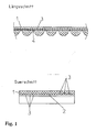
- the toothed belt 1 can be made of a polyurethane base material, for example exist and several tensile cords 2, e.g. made of steel braid include.
- a plurality of conductors 3 are arranged adjacent to the pull strands 2 isolating sections are separated.
- the insulation sections are made by the base material, e.g. Polyurethane, the timing belt 1 is formed.
- Each of the conductors 3 can form a phase and thus a current path.
- the conductor 3 can by a copper braid or by an elastic properties having conductive tape are formed.
- At least one of the pull strands 2 is also provided with conductive properties or serves as a current path.
- the pulley can comprise a lamella sandwich structure, wherein conductive portions are provided on the disc tooth head, which then the Electrical contacting with the conductor or conductors 3 already described enable.
- the toothed belt can have 1 driver in the back of the belt, e.g. to Transportation purposes.
- a current tap in the sense of mating contact can be made using a another pulley can be made, but also a Roller or tension pulley with conductive properties Can be found.
- each belt can be provided with comb the corresponding pulleys.
- each belt forms with Internal conductors 3 have at least one current path.
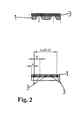
- FIG. 2 The embodiment of a toothed belt with guide profiles according to FIG. 2 corresponds essentially that of FIG. 1, but with the tooth shape has a trapezoidal course.
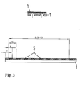
- a timing belt with guide profiles 5 on the back shows the execution Example according to Fig. 3.
- the rear guide profiles 5 are in the belt volume embedded and essentially close with the back surface flush.
- a pulley or roller 7 guiding the toothed belt 1 has, on the circumferential side in the region of the conductors embedded in the toothed belt 1, a toothed wheel 8. As shown, three magnet wheels 8 are arranged on both sides of the roller 7 in the present case, 8 insulation sections 9 being located between the magnet wheels. Another insulation insert 10 is used for electrical isolation from the material of the pulley or roller 7 if it is itself conductive.
- Recesses 11 in the area of the respective magnet wheel are used for recording preferably spring-loaded pins 12, e.g. from a graphite or graphite coated Material.
- the counter contacts 6 are mounted in an insulating support block 13.
- a Insulation plate 14 matched to the inner roll width has guide bores in the area of the pins 12 and takes on the leadership function for the pins 12 also forces on rotation of the pulley or Roll 7 related to the pins 12 occur.
- the insulation sections 9, the insulation insert 10, but also the pole wheels 8 are disc-shaped and releasable component via a bolt 15 the pulley 7 or the roller. In this way, a Adaptation to different timing belts 1 with different arrangements the conductor 3 or different conductor distances are made.
- the base body of the pulley 7 not loaded with a current carrying function.
- this can be used to conduct electricity. They can also Magnet wheels 8 a larger part or the entire width of the pulley 7 take, then the pole wheels in addition to the electrical one increasing power transmission function.
Landscapes
- Engineering & Computer Science (AREA)
- General Engineering & Computer Science (AREA)
- Mechanical Engineering (AREA)
- Devices For Conveying Motion By Means Of Endless Flexible Members (AREA)
- Toys (AREA)
- Vehicle Body Suspensions (AREA)
Abstract

Description
Durch die Verbindung der Vorteile herkömmlicher Riemengetriebe, z.B. geringe Masse, hohe zulässige Umfangskraft, geräuscharmer und schwingungsdämpfender Verlauf, mit denen der Kettengetriebe, wie schlupffreie Bewegungsübertragung, geringe erforderliche Vorspannung und damit niedrige Lagerbelastung, ergibt sich für Zahnriemengetriebe ein sehr breites Einsatzgebiet. Dieses reicht von Kleinstantrieben in feinmechanischen Erzeugnissen bis hin zu Hauptantrieben in Industrieanlagen, da Leistungen von wenigen Watt bis nahezu 100 kW übertragen werden können und Riemengeschwindigkeiten bis im Bereich zu 80 m/s zulässig sind.
Im Bereich am oder zwischen den Riemenzahnfüßen oder auf der Riemenrückseite sind dann die leitfähigen Bereiche und/oder Elemente zum Herstellen einer elektrischen Verbindung freiliegend oder in geeigneter Weise zum elektrischen Kontaktieren zugänglich ausgebildet.
Die Riemenscheibe umfaßt im Bereich der Scheibenzahnköpfe leitfähige Abschnitte, die die leitfähigen Bereiche des Zahnriemens elektrisch kontaktieren.
- Fig. 1
- im oberen Bildteil einen Längsschnitt durch einen Zahnriemenabschnitt und im unteren Bildteil einen Querschnitt des Zahnriemens nach erstem Ausführungsbeispiel;
- Fig. 2
- Längs- und Querschnitt eines Riemens nach dem zweiten Ausführungsbeispiel;
- Fig. 3
- Längs- und Querschnitt eines Riemens mit Leitprofilen auf der Rückseite und
- Fig. 4
- ein Beispiel eines Stromübertragungsrads.
Wie dargestellt, sind im vorliegenden Fall jeweils drei Polräder 8 zu beiden Seiten der Rolle 7 angeordnet, wobei zwischen den Polrädern 8 Isolationsabschnitte 9 befindlich sind. Ein weiterer Isolationseinsatz 10 dient der elektrischen Trennung hin zum Material der Riemenscheibe oder Rolle 7, wenn diese selbst leitfähig ist.
- 1
- Zahnriemen
- 2
- Zugstränge
- 3
- Leiter
- 4
- Quernuten
- 5
- Rückseitenleitprofil
- 6
- Gegenkontakte
- 7
- Riemenscheibe / Rolle
- 8
- Polrad
- 9
- Isolationsabschnitt
- 10
- Isolationseinsatz
- 11
- Rücksprung
- 12
- Stift
- 13
- Tragblock
- 14
- Isolationsplatte
- 15
- Bolzen
Claims (15)
- Vorrichtung zur Kraft- und/oder Bewegungsübertragung mittels Synchrongetriebe, umfassend mindestens einen Zahnriemen sowie mindestens eine Riemenscheibe, wobei der Zahnriemen in der neutralen Biegezone Zugstränge aufweist oder diese Zone als Zugstrang ausgebildet ist,
dadurch gekennzeichnet, daß
im Zahnriemen leitfähige Bereiche vorgesehen und/oder leitfähige Elemente eingebettet sind, welche sich in Riemenlängsrichtung erstrecken, wobei im Bereich am oder zwischen den Riemenzahnfüßen und/oder auf der Riemenrückseite die leitfähigen Bereiche und/oder Elemente zum Herstellen einer elektrischen Verbindung frei liegen oder in geeigneter Weise zum elektrischen Kontaktieren zugänglich sind. - Vorrichtung nach Anspruch 1,
dadurch gekennzeichnet, daß
die leitfähigen Bereiche als metallische Litze oder Bänder ausgebildet und in der neutralen Biegezone, den Zugsträngen benachbart, im Zahnriemen eingebettet sind. - Vorrichtung nach Anspruch 1 oder 2,
dadurch gekennzeichnet, daß
zwischen den leitfähigen Bereichen Isolierabschnitte angeordnet sind, die bevorzugt aus dem Zahnriemen-Werkstoff bestehen. - Vorrichtung nach einem der vorangegangenen Ansprüche,
dadurch gekennzeichnet, daß
mindestens einer der Zugstränge als elektrischer Leiter ausgebildet ist. - Vorrichtung nach einem der vorangegangenen Ansprüche,
dadurch gekennzeichnet, daß
im Bereich zwischen den Riemenzahnfüßen zur elektrischen Kontaktierung eine Quernut oder Aussparung vorhanden ist. - Vorrichtung nach einem der vorangegangenen Ansprüche,
dadurch gekennzeichnet, daß
die Riemenscheibe im Bereich der Scheibenzahnköpfe leitfähige Abschnitte aufweist, welche die leitfähigen Bereiche des Zahnriemens beim Kämmen kontaktieren. - Vorrichtung nach Anspruch 6,
dadurch gekennzeichnet, daß
im Bereich der Scheibenzahnköpfe mehrere in Querrichtung beabstandet angeordnete leitfähige Abschnitte vorgesehen sind, wobei zwischen den leitfähigen Abschnitten Isolierzonen bestehen. - Vorrichtung nach Anspruch 6 oder 7,
dadurch gekennzeichnet, daß
die Riemenscheibe aus einer Lamellen-Sandwich-Struktur mit leitfähigen und isolierenden Lamellen besteht. - Vorrichtung nach einem der vorangegangenen Ansprüche,
dadurch gekennzeichnet, daß
der Zahnriemenrücken eine weitere Verzahnung aufweist, wobei auch oder alternativ über die Riemenrückseite eine elektrische Verbindung zu den leitfähigen Bereichen und/oder leitfähigen Elementen innerhalb des Riemens herstellbar ist. - Vorrichtung nach einem der vorangegangenen Ansprüche,
dadurch gekennzeichnet, daß
zur Gegenkontaktierung bei eingespanntem Riemen eine elektrische Klemmleiste vorgesehen ist. - Vorrichtung nach einem der Ansprüche 1 bis 9,
dadurch gekennzeichnet, daß
zur Gegenkontaktierung mindestens eine weitere Riemenscheibe mit leitfähigen Eigenschaften vorgesehen ist. - Vorrichtung nach einem der Ansprüche 1 bis 9,
dadurch gekennzeichnet, daß
die Gegenkontaktierung über eine leitfähige Eigenschaften aufweisende Laufoder Spannrolle erfolgt. - Vorrichtung nach einem der vorangegangenen Ansprüche,
dadurch gekennzeichnet, daß
mehrere Einzelzahnriemen mit mindestens einem elektrisch leitfähigen Bereich und/oder Element vorgesehen sind, wobei die Einzelzahnriemen mit einer oder mehreren Riemenscheiben kämmen und jeder der Riemen mindestens einen leitfähigen Pfad bildet. - Vorrichtung nach einem der vorangegangenen Ansprüche,
gekennzeichnet durch
einen feststehenden Zahnriemen. - Zahnriemen mit in der neutralen Zone angeordneten Zugsträngen oder einer als Zugstrang ausgebildeten Biegezone,
dadurch gekennzeichnet, daß
leitfähige Bereiche vorgesehen oder eingebettet sind, wobei im Bereich an oder zwischen den Riemenzahnfüßen und/oder auf der Riemenrückseite die leitfähigen Bereiche zum Herstellen einer elektrischen Verbindung zugänglich sind.
Applications Claiming Priority (4)
| Application Number | Priority Date | Filing Date | Title |
|---|---|---|---|
| DE10210601 | 2002-03-11 | ||
| DE10210601 | 2002-03-11 | ||
| DE10232965 | 2002-07-19 | ||
| DE10232965A DE10232965B4 (de) | 2002-03-11 | 2002-07-19 | Antriebsvorrichtung zur Kraft- und/oder Bewegungsübertragung |
Publications (3)
| Publication Number | Publication Date |
|---|---|
| EP1344959A2 true EP1344959A2 (de) | 2003-09-17 |
| EP1344959A3 EP1344959A3 (de) | 2005-04-06 |
| EP1344959B1 EP1344959B1 (de) | 2007-02-21 |
Family
ID=27766695
Family Applications (1)
| Application Number | Title | Priority Date | Filing Date |
|---|---|---|---|
| EP03005330A Expired - Lifetime EP1344959B1 (de) | 2002-03-11 | 2003-03-11 | Vorrichtung zur Kraft- und/oder Bewegungsübertragung mittels Synchrongetriebe |
Country Status (4)
| Country | Link |
|---|---|
| EP (1) | EP1344959B1 (de) |
| AT (1) | ATE354745T1 (de) |
| DE (1) | DE50306554D1 (de) |
| ES (1) | ES2283669T3 (de) |
Cited By (8)
| Publication number | Priority date | Publication date | Assignee | Title |
|---|---|---|---|---|
| WO2005047730A1 (de) * | 2003-11-17 | 2005-05-26 | Bernd Schechinger | Vorrichtung zur kraft- und bewegungsübertragung |
| EP1674419A1 (de) * | 2004-12-24 | 2006-06-28 | Inventio Ag | Anlage mit riemenartigem Antriebsmittel und Verfahren zur Übertragung von elektrischer Energie oder Signalen in einer solchen Anlage |
| EP1700814A1 (de) * | 2005-03-09 | 2006-09-13 | Inventio Ag | Türantrieb mit riemenartigem Antriebsmittel und Aufzugsanlage mit einem solchen Türantrieb |
| EP2157334A1 (de) * | 2008-07-14 | 2010-02-24 | komax Holding AG | Vorrichtung zum linearen Bewegen eines Schlittens |
| DE102007030142B4 (de) * | 2007-06-27 | 2011-08-25 | BRECO Antriebstechnik Breher GmbH & Co., 32457 | Zahnriemen, bestimmt als Teil einer Anordnung zur Erfassung von Zahnriemen-Längenänderungen |
| DE102012010219A1 (de) | 2012-05-23 | 2013-11-28 | Fraunhofer-Gesellschaft zur Förderung der angewandten Forschung e.V. | Vorrichtung zur Energieübertragung bei einem Antrieb |
| DE102012011230A1 (de) | 2012-06-06 | 2013-12-12 | Fraunhofer-Gesellschaft zur Förderung der angewandten Forschung e.V. | Vorrichtung zur Kraft- und/oder Bewegungsübertragung und Fördergerät mit einer solchen Vorrichtung |
| DE102015212401A1 (de) | 2015-07-02 | 2017-01-05 | Spinner Gmbh | Vorrichtung und Verfahren zur Übertragung elektrischer Energie zwischen einer rotierenden und einer stationären Einheit |
Family Cites Families (6)
| Publication number | Priority date | Publication date | Assignee | Title |
|---|---|---|---|---|
| US3068710A (en) * | 1952-12-02 | 1962-12-18 | Continental Gumml Werke Ag | Transmission belt of plastic material |
| DE1292456B (de) * | 1963-01-15 | 1969-04-10 | Franz Felix Dipl Phys | Flachriemen fuer Stollenriemenantriebe |
| JPS61263507A (ja) * | 1985-05-15 | 1986-11-21 | Nippon Mektron Ltd | 帯電防止搬送手段 |
| JPH0781608B2 (ja) * | 1989-10-21 | 1995-09-06 | 株式会社豊田自動織機製作所 | 伝導ベルトの劣化検出装置 |
| IT1251039B (it) * | 1991-08-01 | 1995-05-02 | Pirelli Transmissioni Ind Spa | Metodo e dispositivo per controllare lo stato di usura del tessuto di rivestimento di una cinghia di trasmissione |
| DE10216354A1 (de) * | 2002-04-13 | 2003-10-23 | Ina Schaeffler Kg | Spannvorrichtung |
-
2003
- 2003-03-11 DE DE50306554T patent/DE50306554D1/de not_active Expired - Fee Related
- 2003-03-11 ES ES03005330T patent/ES2283669T3/es not_active Expired - Lifetime
- 2003-03-11 EP EP03005330A patent/EP1344959B1/de not_active Expired - Lifetime
- 2003-03-11 AT AT03005330T patent/ATE354745T1/de not_active IP Right Cessation
Non-Patent Citations (1)
| Title |
|---|
| None |
Cited By (10)
| Publication number | Priority date | Publication date | Assignee | Title |
|---|---|---|---|---|
| WO2005047730A1 (de) * | 2003-11-17 | 2005-05-26 | Bernd Schechinger | Vorrichtung zur kraft- und bewegungsübertragung |
| EP1674419A1 (de) * | 2004-12-24 | 2006-06-28 | Inventio Ag | Anlage mit riemenartigem Antriebsmittel und Verfahren zur Übertragung von elektrischer Energie oder Signalen in einer solchen Anlage |
| CN100591606C (zh) * | 2004-12-24 | 2010-02-24 | 因温特奥股份公司 | 具有皮带状驱动机构的设备、在其中传递电能或信号的方法及其安装方法 |
| EP1700814A1 (de) * | 2005-03-09 | 2006-09-13 | Inventio Ag | Türantrieb mit riemenartigem Antriebsmittel und Aufzugsanlage mit einem solchen Türantrieb |
| DE102007030142B4 (de) * | 2007-06-27 | 2011-08-25 | BRECO Antriebstechnik Breher GmbH & Co., 32457 | Zahnriemen, bestimmt als Teil einer Anordnung zur Erfassung von Zahnriemen-Längenänderungen |
| EP2157334A1 (de) * | 2008-07-14 | 2010-02-24 | komax Holding AG | Vorrichtung zum linearen Bewegen eines Schlittens |
| US8151974B2 (en) | 2008-07-14 | 2012-04-10 | Komax Holding Ag | Device for the linear movement of a carriage |
| DE102012010219A1 (de) | 2012-05-23 | 2013-11-28 | Fraunhofer-Gesellschaft zur Förderung der angewandten Forschung e.V. | Vorrichtung zur Energieübertragung bei einem Antrieb |
| DE102012011230A1 (de) | 2012-06-06 | 2013-12-12 | Fraunhofer-Gesellschaft zur Förderung der angewandten Forschung e.V. | Vorrichtung zur Kraft- und/oder Bewegungsübertragung und Fördergerät mit einer solchen Vorrichtung |
| DE102015212401A1 (de) | 2015-07-02 | 2017-01-05 | Spinner Gmbh | Vorrichtung und Verfahren zur Übertragung elektrischer Energie zwischen einer rotierenden und einer stationären Einheit |
Also Published As
| Publication number | Publication date |
|---|---|
| ATE354745T1 (de) | 2007-03-15 |
| EP1344959B1 (de) | 2007-02-21 |
| ES2283669T3 (es) | 2007-11-01 |
| DE50306554D1 (de) | 2007-04-05 |
| EP1344959A3 (de) | 2005-04-06 |
Similar Documents
| Publication | Publication Date | Title |
|---|---|---|
| EP0789427B1 (de) | Leiterplattenverbinder | |
| DE2848167C2 (de) | Laschenkette für Kegelscheibengetriebe | |
| EP0036452B1 (de) | Bürstenanordnung für dynamoelektrische Maschinen | |
| EP1232974A1 (de) | Fördersystem | |
| EP3147239B1 (de) | Zahnriemen mit integrierten stützrollen | |
| EP1344959B1 (de) | Vorrichtung zur Kraft- und/oder Bewegungsübertragung mittels Synchrongetriebe | |
| EP3635413A1 (de) | Kontaktelementsystem | |
| EP1674419A1 (de) | Anlage mit riemenartigem Antriebsmittel und Verfahren zur Übertragung von elektrischer Energie oder Signalen in einer solchen Anlage | |
| DE2814510C2 (de) | Vorrichtung zum elektrischen Prüfen von mit Bauelementen bestückten Schaltungsplatten | |
| WO2010108509A1 (de) | Elektrischer linearantrieb | |
| DE69218304T2 (de) | Kettenriemen | |
| EP0254770B1 (de) | Elektrische Kontaktvorrichtung | |
| DE10232965B4 (de) | Antriebsvorrichtung zur Kraft- und/oder Bewegungsübertragung | |
| DE19947806B4 (de) | Kettenziehmaschine zum kontinuierlichen Ziehen von Ziehgut | |
| DE2044434B2 (de) | Längliches, starres, aus zwei Reihen von Blöcken gebildetes Bauelement | |
| DE60111899T2 (de) | Schlitten für Kabelführungskette | |
| DE2438815A1 (de) | Antriebssystem fuer einen endlosen riemen | |
| EP2499070B1 (de) | Fördereinrichtung | |
| DE102009022022A1 (de) | Verbindungsvorrichtung | |
| AT394489B (de) | Vorhangzugeinrichtung | |
| DE102018127304B3 (de) | Stromabnehmer, Schleifleitung und Schleifleitungssystem | |
| DE871914C (de) | Einrichtung zur stufenweisen, insbesondere feinstufigen Regelung groesserer elektrischer Leistungen | |
| DE4300919C1 (de) | Vorrichtung zur Einstellung eines Rastabstandes | |
| AT6801U1 (de) | Umlaufender mitnehmer | |
| DE2712850A1 (de) | Elektromagnetische bremse mit gelenkig montierten bremsschuhen fuer schienenfahrzeuge |
Legal Events
| Date | Code | Title | Description |
|---|---|---|---|
| PUAI | Public reference made under article 153(3) epc to a published international application that has entered the european phase |
Free format text: ORIGINAL CODE: 0009012 |
|
| AK | Designated contracting states |
Kind code of ref document: A2 Designated state(s): AT BE BG CH CY CZ DE DK EE ES FI FR GB GR HU IE IT LI LU MC NL PT RO SE SI SK TR |
|
| AX | Request for extension of the european patent |
Extension state: AL LT LV MK |
|
| PUAL | Search report despatched |
Free format text: ORIGINAL CODE: 0009013 |
|
| AK | Designated contracting states |
Kind code of ref document: A3 Designated state(s): AT BE BG CH CY CZ DE DK EE ES FI FR GB GR HU IE IT LI LU MC NL PT RO SE SI SK TR |
|
| AX | Request for extension of the european patent |
Extension state: AL LT LV MK |
|
| RIC1 | Information provided on ipc code assigned before grant |
Ipc: 7F 16G 1/00 B Ipc: 7F 16G 1/28 A |
|
| 17P | Request for examination filed |
Effective date: 20051006 |
|
| AKX | Designation fees paid |
Designated state(s): AT BE BG CH CY CZ DE DK EE ES FI FR GB GR HU IE IT LI LU MC NL PT RO SE SI SK TR |
|
| GRAP | Despatch of communication of intention to grant a patent |
Free format text: ORIGINAL CODE: EPIDOSNIGR1 |
|
| GRAS | Grant fee paid |
Free format text: ORIGINAL CODE: EPIDOSNIGR3 |
|
| GRAA | (expected) grant |
Free format text: ORIGINAL CODE: 0009210 |
|
| AK | Designated contracting states |
Kind code of ref document: B1 Designated state(s): AT BE BG CH CY CZ DE DK EE ES FI FR GB GR HU IE IT LI LU MC NL PT RO SE SI SK TR |
|
| PG25 | Lapsed in a contracting state [announced via postgrant information from national office to epo] |
Ref country code: DK Free format text: LAPSE BECAUSE OF FAILURE TO SUBMIT A TRANSLATION OF THE DESCRIPTION OR TO PAY THE FEE WITHIN THE PRESCRIBED TIME-LIMIT Effective date: 20070221 Ref country code: SI Free format text: LAPSE BECAUSE OF FAILURE TO SUBMIT A TRANSLATION OF THE DESCRIPTION OR TO PAY THE FEE WITHIN THE PRESCRIBED TIME-LIMIT Effective date: 20070221 Ref country code: IE Free format text: LAPSE BECAUSE OF FAILURE TO SUBMIT A TRANSLATION OF THE DESCRIPTION OR TO PAY THE FEE WITHIN THE PRESCRIBED TIME-LIMIT Effective date: 20070221 |
|
| REG | Reference to a national code |
Ref country code: GB Ref legal event code: FG4D Free format text: NOT ENGLISH |
|
| REG | Reference to a national code |
Ref country code: CH Ref legal event code: EP |
|
| REF | Corresponds to: |
Ref document number: 50306554 Country of ref document: DE Date of ref document: 20070405 Kind code of ref document: P |
|
| REG | Reference to a national code |
Ref country code: IE Ref legal event code: FG4D Free format text: LANGUAGE OF EP DOCUMENT: GERMAN |
|
| REG | Reference to a national code |
Ref country code: RO Ref legal event code: EPE |
|
| PG25 | Lapsed in a contracting state [announced via postgrant information from national office to epo] |
Ref country code: BG Free format text: LAPSE BECAUSE OF EXPIRATION OF PROTECTION Effective date: 20070522 |
|
| REG | Reference to a national code |
Ref country code: SE Ref legal event code: TRGR |
|
| GBT | Gb: translation of ep patent filed (gb section 77(6)(a)/1977) |
Effective date: 20070521 |
|
| REG | Reference to a national code |
Ref country code: CH Ref legal event code: NV Representative=s name: ISLER & PEDRAZZINI AG |
|
| PG25 | Lapsed in a contracting state [announced via postgrant information from national office to epo] |
Ref country code: PT Free format text: LAPSE BECAUSE OF FAILURE TO SUBMIT A TRANSLATION OF THE DESCRIPTION OR TO PAY THE FEE WITHIN THE PRESCRIBED TIME-LIMIT Effective date: 20070723 |
|
| REG | Reference to a national code |
Ref country code: HU Ref legal event code: AG4A Ref document number: E001826 Country of ref document: HU |
|
| REG | Reference to a national code |
Ref country code: IE Ref legal event code: FD4D |
|
| REG | Reference to a national code |
Ref country code: CH Ref legal event code: PCAR Free format text: ISLER & PEDRAZZINI AG;POSTFACH 1772;8027 ZUERICH (CH) |
|
| REG | Reference to a national code |
Ref country code: ES Ref legal event code: FG2A Ref document number: 2283669 Country of ref document: ES Kind code of ref document: T3 |
|
| PG25 | Lapsed in a contracting state [announced via postgrant information from national office to epo] |
Ref country code: SK Free format text: LAPSE BECAUSE OF FAILURE TO SUBMIT A TRANSLATION OF THE DESCRIPTION OR TO PAY THE FEE WITHIN THE PRESCRIBED TIME-LIMIT Effective date: 20070221 |
|
| PLBE | No opposition filed within time limit |
Free format text: ORIGINAL CODE: 0009261 |
|
| STAA | Information on the status of an ep patent application or granted ep patent |
Free format text: STATUS: NO OPPOSITION FILED WITHIN TIME LIMIT |
|
| BERE | Be: lapsed |
Owner name: SCHECHINGER, BERND Effective date: 20070331 |
|
| PG25 | Lapsed in a contracting state [announced via postgrant information from national office to epo] |
Ref country code: BE Free format text: LAPSE BECAUSE OF NON-PAYMENT OF DUE FEES Effective date: 20070331 |
|
| 26N | No opposition filed |
Effective date: 20071122 |
|
| PG25 | Lapsed in a contracting state [announced via postgrant information from national office to epo] |
Ref country code: MC Free format text: LAPSE BECAUSE OF NON-PAYMENT OF DUE FEES Effective date: 20070331 |
|
| PG25 | Lapsed in a contracting state [announced via postgrant information from national office to epo] |
Ref country code: GR Free format text: LAPSE BECAUSE OF FAILURE TO SUBMIT A TRANSLATION OF THE DESCRIPTION OR TO PAY THE FEE WITHIN THE PRESCRIBED TIME-LIMIT Effective date: 20070522 |
|
| PG25 | Lapsed in a contracting state [announced via postgrant information from national office to epo] |
Ref country code: EE Free format text: LAPSE BECAUSE OF FAILURE TO SUBMIT A TRANSLATION OF THE DESCRIPTION OR TO PAY THE FEE WITHIN THE PRESCRIBED TIME-LIMIT Effective date: 20070221 |
|
| PGFP | Annual fee paid to national office [announced via postgrant information from national office to epo] |
Ref country code: AT Payment date: 20090325 Year of fee payment: 7 Ref country code: ES Payment date: 20090318 Year of fee payment: 7 Ref country code: HU Payment date: 20090309 Year of fee payment: 7 |
|
| PGFP | Annual fee paid to national office [announced via postgrant information from national office to epo] |
Ref country code: CZ Payment date: 20090304 Year of fee payment: 7 Ref country code: FI Payment date: 20090330 Year of fee payment: 7 Ref country code: RO Payment date: 20090226 Year of fee payment: 7 |
|
| PGFP | Annual fee paid to national office [announced via postgrant information from national office to epo] |
Ref country code: CH Payment date: 20090331 Year of fee payment: 7 Ref country code: GB Payment date: 20090302 Year of fee payment: 7 |
|
| PG25 | Lapsed in a contracting state [announced via postgrant information from national office to epo] |
Ref country code: CY Free format text: LAPSE BECAUSE OF FAILURE TO SUBMIT A TRANSLATION OF THE DESCRIPTION OR TO PAY THE FEE WITHIN THE PRESCRIBED TIME-LIMIT Effective date: 20070221 |
|
| PG25 | Lapsed in a contracting state [announced via postgrant information from national office to epo] |
Ref country code: LU Free format text: LAPSE BECAUSE OF NON-PAYMENT OF DUE FEES Effective date: 20070311 |
|
| PGFP | Annual fee paid to national office [announced via postgrant information from national office to epo] |
Ref country code: DE Payment date: 20090527 Year of fee payment: 7 Ref country code: FR Payment date: 20090327 Year of fee payment: 7 Ref country code: IT Payment date: 20090319 Year of fee payment: 7 Ref country code: SE Payment date: 20090319 Year of fee payment: 7 Ref country code: TR Payment date: 20090211 Year of fee payment: 7 |
|
| PGFP | Annual fee paid to national office [announced via postgrant information from national office to epo] |
Ref country code: NL Payment date: 20090331 Year of fee payment: 7 |
|
| REG | Reference to a national code |
Ref country code: NL Ref legal event code: V1 Effective date: 20101001 |
|
| REG | Reference to a national code |
Ref country code: CH Ref legal event code: PL |
|
| EUG | Se: european patent has lapsed | ||
| GBPC | Gb: european patent ceased through non-payment of renewal fee |
Effective date: 20100311 |
|
| PG25 | Lapsed in a contracting state [announced via postgrant information from national office to epo] |
Ref country code: FI Free format text: LAPSE BECAUSE OF NON-PAYMENT OF DUE FEES Effective date: 20100311 Ref country code: AT Free format text: LAPSE BECAUSE OF NON-PAYMENT OF DUE FEES Effective date: 20100311 Ref country code: CZ Free format text: LAPSE BECAUSE OF NON-PAYMENT OF DUE FEES Effective date: 20100311 |
|
| REG | Reference to a national code |
Ref country code: FR Ref legal event code: ST Effective date: 20101130 |
|
| PG25 | Lapsed in a contracting state [announced via postgrant information from national office to epo] |
Ref country code: NL Free format text: LAPSE BECAUSE OF NON-PAYMENT OF DUE FEES Effective date: 20101001 Ref country code: FR Free format text: LAPSE BECAUSE OF NON-PAYMENT OF DUE FEES Effective date: 20100331 |
|
| PG25 | Lapsed in a contracting state [announced via postgrant information from national office to epo] |
Ref country code: LI Free format text: LAPSE BECAUSE OF NON-PAYMENT OF DUE FEES Effective date: 20100331 Ref country code: HU Free format text: LAPSE BECAUSE OF NON-PAYMENT OF DUE FEES Effective date: 20100312 Ref country code: DE Free format text: LAPSE BECAUSE OF NON-PAYMENT OF DUE FEES Effective date: 20101001 Ref country code: CH Free format text: LAPSE BECAUSE OF NON-PAYMENT OF DUE FEES Effective date: 20100331 |
|
| PG25 | Lapsed in a contracting state [announced via postgrant information from national office to epo] |
Ref country code: IT Free format text: LAPSE BECAUSE OF NON-PAYMENT OF DUE FEES Effective date: 20100311 Ref country code: GB Free format text: LAPSE BECAUSE OF NON-PAYMENT OF DUE FEES Effective date: 20100311 |
|
| REG | Reference to a national code |
Ref country code: ES Ref legal event code: FD2A Effective date: 20110415 |
|
| PG25 | Lapsed in a contracting state [announced via postgrant information from national office to epo] |
Ref country code: RO Free format text: LAPSE BECAUSE OF NON-PAYMENT OF DUE FEES Effective date: 20100311 |
|
| PG25 | Lapsed in a contracting state [announced via postgrant information from national office to epo] |
Ref country code: ES Free format text: LAPSE BECAUSE OF NON-PAYMENT OF DUE FEES Effective date: 20110404 |
|
| PG25 | Lapsed in a contracting state [announced via postgrant information from national office to epo] |
Ref country code: ES Free format text: LAPSE BECAUSE OF NON-PAYMENT OF DUE FEES Effective date: 20100312 |
|
| PG25 | Lapsed in a contracting state [announced via postgrant information from national office to epo] |
Ref country code: SE Free format text: LAPSE BECAUSE OF NON-PAYMENT OF DUE FEES Effective date: 20100312 |
|
| PG25 | Lapsed in a contracting state [announced via postgrant information from national office to epo] |
Ref country code: TR Free format text: LAPSE BECAUSE OF NON-PAYMENT OF DUE FEES Effective date: 20100311 |