EP1344988B1 - Kohlenstoffhaltiger Formkörper zur Beheizung von Räumen - Google Patents
Kohlenstoffhaltiger Formkörper zur Beheizung von Räumen Download PDFInfo
- Publication number
- EP1344988B1 EP1344988B1 EP03004940A EP03004940A EP1344988B1 EP 1344988 B1 EP1344988 B1 EP 1344988B1 EP 03004940 A EP03004940 A EP 03004940A EP 03004940 A EP03004940 A EP 03004940A EP 1344988 B1 EP1344988 B1 EP 1344988B1
- Authority
- EP
- European Patent Office
- Prior art keywords
- carbon
- plate
- moulded body
- decorative layer
- rooms
- Prior art date
- Legal status (The legal status is an assumption and is not a legal conclusion. Google has not performed a legal analysis and makes no representation as to the accuracy of the status listed.)
- Expired - Lifetime
Links
- 238000010438 heat treatment Methods 0.000 title claims description 16
- OKTJSMMVPCPJKN-UHFFFAOYSA-N Carbon Chemical compound [C] OKTJSMMVPCPJKN-UHFFFAOYSA-N 0.000 claims abstract description 41
- 229910052799 carbon Inorganic materials 0.000 claims abstract description 32
- 239000000919 ceramic Substances 0.000 claims abstract description 18
- 230000001681 protective effect Effects 0.000 claims abstract description 14
- 239000011159 matrix material Substances 0.000 claims abstract description 5
- 239000000203 mixture Substances 0.000 claims description 13
- 239000004033 plastic Substances 0.000 claims description 11
- 229920003023 plastic Polymers 0.000 claims description 11
- 239000000571 coke Substances 0.000 claims description 5
- 229910002804 graphite Inorganic materials 0.000 claims description 5
- 239000010439 graphite Substances 0.000 claims description 5
- RHZUVFJBSILHOK-UHFFFAOYSA-N anthracen-1-ylmethanolate Chemical compound C1=CC=C2C=C3C(C[O-])=CC=CC3=CC2=C1 RHZUVFJBSILHOK-UHFFFAOYSA-N 0.000 claims description 4
- 239000003830 anthracite Substances 0.000 claims description 4
- 239000006229 carbon black Substances 0.000 claims description 3
- 239000004640 Melamine resin Substances 0.000 claims description 2
- 229920000877 Melamine resin Polymers 0.000 claims description 2
- ISWSIDIOOBJBQZ-UHFFFAOYSA-N Phenol Chemical compound OC1=CC=CC=C1 ISWSIDIOOBJBQZ-UHFFFAOYSA-N 0.000 claims description 2
- ODINCKMPIJJUCX-UHFFFAOYSA-N calcium oxide Inorganic materials [Ca]=O ODINCKMPIJJUCX-UHFFFAOYSA-N 0.000 claims description 2
- 239000000470 constituent Substances 0.000 claims description 2
- CPLXHLVBOLITMK-UHFFFAOYSA-N magnesium oxide Inorganic materials [Mg]=O CPLXHLVBOLITMK-UHFFFAOYSA-N 0.000 claims description 2
- VYPSYNLAJGMNEJ-UHFFFAOYSA-N Silicium dioxide Chemical compound O=[Si]=O VYPSYNLAJGMNEJ-UHFFFAOYSA-N 0.000 claims 2
- KKCBUQHMOMHUOY-UHFFFAOYSA-N Na2O Inorganic materials [O-2].[Na+].[Na+] KKCBUQHMOMHUOY-UHFFFAOYSA-N 0.000 claims 1
- PNEYBMLMFCGWSK-UHFFFAOYSA-N aluminium oxide Inorganic materials [O-2].[O-2].[O-2].[Al+3].[Al+3] PNEYBMLMFCGWSK-UHFFFAOYSA-N 0.000 claims 1
- 229910052681 coesite Inorganic materials 0.000 claims 1
- 229910052593 corundum Inorganic materials 0.000 claims 1
- 229910052906 cristobalite Inorganic materials 0.000 claims 1
- 150000002118 epoxides Chemical class 0.000 claims 1
- 229910052500 inorganic mineral Inorganic materials 0.000 claims 1
- 239000011707 mineral Substances 0.000 claims 1
- 229910021382 natural graphite Inorganic materials 0.000 claims 1
- 239000002006 petroleum coke Substances 0.000 claims 1
- NOTVAPJNGZMVSD-UHFFFAOYSA-N potassium monoxide Inorganic materials [K]O[K] NOTVAPJNGZMVSD-UHFFFAOYSA-N 0.000 claims 1
- 239000000377 silicon dioxide Substances 0.000 claims 1
- 229910052682 stishovite Inorganic materials 0.000 claims 1
- 229910052905 tridymite Inorganic materials 0.000 claims 1
- 229910001845 yogo sapphire Inorganic materials 0.000 claims 1
- 238000003491 array Methods 0.000 abstract 1
- 239000000463 material Substances 0.000 description 16
- 238000000465 moulding Methods 0.000 description 16
- 238000009413 insulation Methods 0.000 description 8
- 238000004519 manufacturing process Methods 0.000 description 8
- 239000002245 particle Substances 0.000 description 7
- 229920000049 Carbon (fiber) Polymers 0.000 description 6
- 239000004917 carbon fiber Substances 0.000 description 6
- 241001295925 Gegenes Species 0.000 description 5
- 239000004020 conductor Substances 0.000 description 5
- 239000011248 coating agent Substances 0.000 description 4
- 238000000576 coating method Methods 0.000 description 4
- 238000000034 method Methods 0.000 description 4
- 239000000758 substrate Substances 0.000 description 4
- 239000004568 cement Substances 0.000 description 3
- 229910021385 hard carbon Inorganic materials 0.000 description 3
- 239000000615 nonconductor Substances 0.000 description 3
- 230000000007 visual effect Effects 0.000 description 3
- 239000003245 coal Substances 0.000 description 2
- 238000004939 coking Methods 0.000 description 2
- -1 inter alia Substances 0.000 description 2
- 150000001247 metal acetylides Chemical class 0.000 description 2
- 239000004570 mortar (masonry) Substances 0.000 description 2
- 239000011224 oxide ceramic Substances 0.000 description 2
- 229910052574 oxide ceramic Inorganic materials 0.000 description 2
- 239000003208 petroleum Substances 0.000 description 2
- 239000002994 raw material Substances 0.000 description 2
- 239000004071 soot Substances 0.000 description 2
- 229910018072 Al 2 O 3 Inorganic materials 0.000 description 1
- 239000004593 Epoxy Substances 0.000 description 1
- 229910004298 SiO 2 Inorganic materials 0.000 description 1
- 239000000654 additive Substances 0.000 description 1
- 239000000853 adhesive Substances 0.000 description 1
- 230000001070 adhesive effect Effects 0.000 description 1
- 239000010425 asbestos Substances 0.000 description 1
- 239000011230 binding agent Substances 0.000 description 1
- 150000001722 carbon compounds Chemical class 0.000 description 1
- 239000011203 carbon fibre reinforced carbon Substances 0.000 description 1
- 239000003575 carbonaceous material Substances 0.000 description 1
- 239000011294 coal tar pitch Substances 0.000 description 1
- 238000004040 coloring Methods 0.000 description 1
- 239000002131 composite material Substances 0.000 description 1
- 239000004567 concrete Substances 0.000 description 1
- 238000005034 decoration Methods 0.000 description 1
- 230000032798 delamination Effects 0.000 description 1
- 238000007598 dipping method Methods 0.000 description 1
- 239000000806 elastomer Substances 0.000 description 1
- 229920001971 elastomer Polymers 0.000 description 1
- 230000005611 electricity Effects 0.000 description 1
- 238000005516 engineering process Methods 0.000 description 1
- 239000004744 fabric Substances 0.000 description 1
- 239000000835 fiber Substances 0.000 description 1
- 239000012530 fluid Substances 0.000 description 1
- 239000006260 foam Substances 0.000 description 1
- 238000009472 formulation Methods 0.000 description 1
- 238000005087 graphitization Methods 0.000 description 1
- 230000017525 heat dissipation Effects 0.000 description 1
- 239000011810 insulating material Substances 0.000 description 1
- 229910052751 metal Inorganic materials 0.000 description 1
- 239000002184 metal Substances 0.000 description 1
- 238000005058 metal casting Methods 0.000 description 1
- 150000002739 metals Chemical class 0.000 description 1
- 150000004767 nitrides Chemical class 0.000 description 1
- 238000002360 preparation method Methods 0.000 description 1
- 239000003870 refractory metal Substances 0.000 description 1
- 229910052895 riebeckite Inorganic materials 0.000 description 1
- 239000007787 solid Substances 0.000 description 1
- XLYOFNOQVPJJNP-UHFFFAOYSA-N water Substances O XLYOFNOQVPJJNP-UHFFFAOYSA-N 0.000 description 1
Images

Classifications
-
- F—MECHANICAL ENGINEERING; LIGHTING; HEATING; WEAPONS; BLASTING
- F24—HEATING; RANGES; VENTILATING
- F24D—DOMESTIC- OR SPACE-HEATING SYSTEMS, e.g. CENTRAL HEATING SYSTEMS; DOMESTIC HOT-WATER SUPPLY SYSTEMS; ELEMENTS OR COMPONENTS THEREFOR
- F24D13/00—Electric heating systems
- F24D13/02—Electric heating systems solely using resistance heating, e.g. underfloor heating
- F24D13/022—Electric heating systems solely using resistance heating, e.g. underfloor heating resistances incorporated in construction elements
-
- Y—GENERAL TAGGING OF NEW TECHNOLOGICAL DEVELOPMENTS; GENERAL TAGGING OF CROSS-SECTIONAL TECHNOLOGIES SPANNING OVER SEVERAL SECTIONS OF THE IPC; TECHNICAL SUBJECTS COVERED BY FORMER USPC CROSS-REFERENCE ART COLLECTIONS [XRACs] AND DIGESTS
- Y02—TECHNOLOGIES OR APPLICATIONS FOR MITIGATION OR ADAPTATION AGAINST CLIMATE CHANGE
- Y02B—CLIMATE CHANGE MITIGATION TECHNOLOGIES RELATED TO BUILDINGS, e.g. HOUSING, HOUSE APPLIANCES OR RELATED END-USER APPLICATIONS
- Y02B30/00—Energy efficient heating, ventilation or air conditioning [HVAC]
Definitions
- the invention relates to a ceramic, electrically conductive, consisting of a carbon matrix plate, which forms with a smooth protective and decorative layer thereon a flat shaped body as a decorative and electrical resistance heating element for the inner surfaces of rooms.
- JP 55134229 describes a plate whose core consists of a resin-impregnated fabric of carbon fibers, which are contacted with lead threads.
- the acting as an electrical resistance element core of the plate is covered by an insulating material.
- the complex structure of such a plate requires a considerable manufacturing effort.
- one or more electrically conductive components such as a cement, inter alia, components are added; This mixture hardens hydraulically in the form of a mechanically stable plate.
- a cement inter alia, components
- This mixture hardens hydraulically in the form of a mechanically stable plate.
- To JP 63131932 Cement and carbon fibers and carbon black are mixed and formed into a homogeneous plate and cured.
- carbon fibers are placed in layers in a cementitious plate.
- EP 204672 The cementitious plate is constructed in three layers, with the central position of the outer through distinguishes graphite powder contained.
- To CN 2174661 is located between a space-oriented towards the bottom plate and a space-oriented insulation layer, a layer of adhesive with carbon powder introduced.
- Plates of this type are inexpensive to manufacture and are suitable for certain applications described in these documents.
- a strand-shaped heating element is placed in a meandering manner in a cement- or asphaltene-containing plate, JP 7106057 .
- JP 7106057 a cement- or asphaltene-containing plate
- JP 7106057 a multi-layered plate assembly is described, which requires a considerable manufacturing effort.
- the disadvantage of the plates described in these six publications is also that they are not suitable for easily kept clean (living) rooms because of a lack of smooth surface.
- one or more electrically conductive components such as a plastic or elastomer, inter alia, components are added. Such mixtures are molded and cured by different methods. As products more or less flexible plates are described with a plastic matrix. To JP 9260035 Carbon fibers are incorporated into a multi-layered mat with a plastic matrix. To JP 6313570 Soot is used as an electrically conductive component in a multi-layered plate. The sequence of layers required in such plates must be secured during manufacture. For example, it may not happen that a rather fluid layer of rather solid layers slides off. There are also risks in the finished (hardened) state, eg due to delamination; such cracks can heat flow from the heat conductor layer to the room significantly affect. In general, plastic plates with rather higher heat transfer resistances have to be expected from the plate to the space than in the case of ceramic plates according to the invention.
- Another group of components that are used in the floors, walls or ceilings of rooms as space heaters in the form of electrical resistance elements are the ceramic tiles already mentioned above.
- FR 2 681 753 a layer of ceramic tiles is combined with a layer of a planar heating element made of carbon fibers in a system. Each of the two layers is artificially applied in a separate step on the prepared space surface.
- the ceramic tiles carry a (full-surface) coating on the rear side opposite the visible side, which represents an electrical resistance. This can heat the tiles laid on the room surfaces and the adjoining room when passing electricity.
- such tiles consist of three layers: the glaze on the visible side, the oxide ceramic shards in the middle and the resistance coating on the back.
- a resistance heating element on the.
- the object of this invention patent application was therefore to provide a simpler structure for an electrically conductive, consisting essentially of a ceramic plate and thereon smooth protective and decorative layer existing flat body for covering floors, walls or ceilings of rooms. Such a shaped body is intended to serve for heating rooms by means of direct passage of electrical current. Another object was to improve the inertia of the heating system by reducing the mass to be heated and the heat transfer resistances.
- the actual plate-shaped body of the type mentioned contains carbon.
- the actual plate of the molding can be made entirely or partially of carbon.
- the preparation of such proportionately made of carbon existing ceramic moldings corresponds to the techniques known from the oxide ceramic, the production of completely. Carbon existing ceramic moldings is described for example in ULLMANN'S ENCYCLOPEDIA OF INDUSTRIAL CHEMISTRY, Vol. A5, VCH Verlagsgesellschaft mbh, Weinheim, 1986, pp. 103 to 113, wherein in the present case the graphitization step is omitted.
- the conventional oxide materials that make up tiles are non-conductors, they are also unsuitable as a heat conductor.
- carbons, especially graphites are used as heat conductors - mainly in high-temperature technology.
- the specific electrical resistances of the graphites are usually below 10 ⁇ m. This property implies that a resistor made of graphite should either have a small cross section or be particularly long in order to obtain technically and economically interesting solutions for a heating conductor.
- Higher specific electrical resistances have carbon materials that are not graphitized but have undergone coking, also called "hard-burn carbon". Such hard-burn carbon are cheaper because of the lower production costs than graphite.
- Hard-burned carbons are one possible embodiment of the mechanically stable substrate of the flat shaped body according to the invention.
- Mixing materials are produced from ceramic oxides and carbons.
- Other additives such as carbides, nitrides or refractory metals are also known for such mixed materials, as described in the above-mentioned prior art, for example GB 2 045 737 .
- the carbons contained in such ceramic mixed materials can be of very different nature. Because of the diversity of the structure of the mixed materials to achieve the desired properties - in particular specific electrical resistance and mechanical strength - the content of carbon in the mixed material in a wide Range vary.
- mixed materials with carbon contents of 10 to 100% by weight are another possible embodiment of the mechanically stable substrate.
- Both the hard carbon and the mixed material can form the actual plate of the molding.
- the plate is the main body of the molding according to the invention.
- the plate provides sufficient mechanical stability and it forms the electrical resistance, which can be heated by direct passage of electrical current and used as space heating.
- carbon in the plate is important for the desired properties but also the type and shape of the carbon. Since virtually all carbons are electrically conductive, they can all be contained in the plate.
- the basis of the various carbons are petroleum or coal or anthracite. While anthracite can be used directly, coals are first produced from petroleum or coal. Depending on the genesis and production, the specific electrical resistance of the coke varies. The electrical conductivity of cokes is generally lower than that of artificially produced electrographites or natural graphites.
- carbon black or carbon or graphite fibers are further forms of the carbon black or carbon or graphite fibers. All of these types of carbon may be contained individually or in mixtures with each other in the plate. The cheap ones Carbons such as anthracite and cokes are preferred.
- the shape or shape of the carbon species is of subordinate importance for the specific electrical resistance of the shaped article according to the invention.
- the carbon is only partially present in the plate next to e.g. contain oxidic constituents, so the shape of the single carbon particle is important.
- tiny spherical carbon particles - such as soot - have fewer contacts with each other than elongated carbon particles - such as carbon fibers.
- the plate has significantly better electrical conductivity or significantly lower electrical resistivity than carbon particles isolated from each other. That is, plates with spherical carbon particles have higher, plates with needlelike carbon particles have lower specific electrical resistances.
- the sheet-like shaped body for covering the inner surfaces of rooms and for heating these spaces are those shaped bodies whose plates have a specific electrical resistance of 10 to 500 ⁇ m, preferably 20 to 100 ⁇ m. It will be apparent from the above-discussed types and shapes of carbons and "hard burn carbon” and “mix” types of slabs that there is a wide range of formulations for the inventive sheet Shaped body to achieve the desired electrical resistivity.
- plastics are good electrical insulators, which is why this group of materials offers as a protective and decorative layer.
- plastics are excluded from use as a protective and decorative layer, which are not sufficiently durable. It has layers of 0.3 to 4 mm thickness from the group of hard plastics such as Epoxy, phenolic, melamine resin or mixtures thereof, which is not to exclude other plastics for this application.
- the plate of the shaped body according to the invention could be enclosed on all sides by the protective and decorative layer, it is seen from the opening of this layer by the necessary electrical contacting of the plate. Because of certain manufacturing techniques (dipping) would be such a comprehensive coating on. However, it is more material-intensive than a substantially one-sided coating of the flat shaped body, in which the narrow edges are covered completely or proportionately with the protective and decorative layer.
- the substantially unilaterally coated flat body also has the advantage that this body because of the porosity of the plate when laying in a fresh and wet mortar bed some water from the mortar attracts and thus adheres well.
- the substantially one-sided coated flat moldings are used as a covering of room surfaces. If they are to be used at the same time as space heating, it is expedient not to incorporate each individual molded body in an electrical circuit as an ohmic resistance and regulate each individual molded body in terms of amount of current and applied voltage, but to combine several moldings in a circuit.
- the flat body (resistors) are electrically connected to each other and it is usually a Series connection of individual resistors made, which does not preclude a parallel connection or a combination of series and parallel connection in special cases.
- the total resistance in a circuit is composed in series connection of the sum of the series-connected individual resistors (individual moldings) together.
- the heating power is designed so that it is up to 200 W / m 2 .
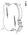
- Fig. 1 shows a two-layered sheet-shaped body 1 with a ceramic plate 2 containing carbon.
- the plate slabs is over the entire surface with a smooth protective and decorative layer 3.
- Fig. 2 shows an arrangement 4 of sheet-like moldings 1, which are electrically connected to each other and which are connected in series in this case.
- This series of ohmic resistors is connected to a suitable power source 5 (direct or alternating current).
- the plate 2 consisted of 100% by weight of carbon.
- the raw material used was a coke from Marathon / Burghausen Germany in a fineness of 20 ⁇ m mean grain diameter. Its proportion of the total mixture was 43.5 wt .-%. 18.5% by weight of electrographite with 30 ⁇ m average grain diameter added to the driers.
- the bulk density was 1.64 g / cm 3
- the flexural strength 50 N / mm 2 and the electrical resistivity 40 ⁇ m.
- FIG. 2 An example of the arrangement of shaped bodies according to the invention on a room surface is shown in FIG. 2.
Landscapes
- Engineering & Computer Science (AREA)
- Physics & Mathematics (AREA)
- Thermal Sciences (AREA)
- Chemical & Material Sciences (AREA)
- Combustion & Propulsion (AREA)
- Mechanical Engineering (AREA)
- General Engineering & Computer Science (AREA)
- Resistance Heating (AREA)
- Finishing Walls (AREA)
- Floor Finish (AREA)
- Surface Heating Bodies (AREA)
Description
- Gegenstand der Erfindung ist eine keramische, elektrisch leitende, aus einer Kohlenstoffmatrix bestehende Platte , die mit einer darauf befindlichen glatten Schutz- und Dekorationsschicht einen flächigen Formkörper als Dekorations- und elektrisches Widerstandsheizelement für die Innenflächen von Räumen bildet.
- Raumheizungen mit elektrischen Widerstandselementen in Böden, Wänden oder Decken dieser Räume sind vielfach beschrieben. Häufig werden vielschichtige Elemente eingesetzt, die entweder an den Raumflächen sichtbar sind oder durch weitere Bauelemente abgedeckt sind. Die Vielschichtigkeit ergibt sich aus den unterschiedlichen Aufgaben, die von den Elementen zu erfüllen sind. Beispielsweise sind folgende Aufgaben zu nennen:
- Bereitstellung ausreichender mechanischer Stabilität,
- Beheizbarkeit des Raumes,
- Isolierung von Personen gegen elektrischen Strom,
- Bereitstellung von zweckmäßigen Nutzflächen (Begehbarkeit= Strapazierfestigkeit; Nassfestigkeit; gewünschte optische Wirkung der Wände, Helligkeit der Decke; usw.),
- Dämmung gegen Wärmeabfluss,
- Dämmung gegen (Tritt-)Schall.
- Zur Minderung der Komplexität der Anforderungen und der Lösungen wurden auch solche Lösungen realisiert, bei denen das den Raum beheizende elektrische Widerstandselement möglichst dicht an der sichtbaren Oberfläche von Böden, Wänden oder Decken ist. Das bedeutet, dass bei diesen Lösungen einige der Anforderungen nicht mehr durch das Bauteil erbracht werden müssen, z.B. Dämmung gegen Wärmeabfluss oder Dämmung gegen (Tritt-)Schall. Solche Bauteile sind z.B. keramische Fliesen, Beton- bzw. Asbestzementplatten oder kunstharzgebundene Platten, in denen ein elektrischer Widerstand integriert ist. Sie sind vielfach beschrieben:
- In
JP 55134229 - In anderen Fällen werden eine oder mehrere elektrisch leitende Komponenten z.B. einem Zement u.a. Komponenten beigemischt; diese Mischung härtet hydraulisch in Form einer mechanisch stabilen Platte aus. Nach
JP 63131932 JP 6068962 JP 1313876 EP 204672 CN 2174661 befindet sich zwischen einer zum Raum hin orientierten Bodenplatte und einer vom Raum weg orientierten Isolationsschicht eine Lage Kleber mit eingebrachtem Kohlenstoffpulver. Platten dieser Art sind preiswert herzustellen und eignen sich für bestimmte in diesen Schriften geschilderte Anwendungen. In einem weiteren Fall wird ein strangförmiges Heizelement in einer zement- oder asphalthaltigen Platte mäanderförmig abgelegt,JP 7106057 - In anderen Fällen werden eine oder mehrere elektrisch leitende Komponenten z.B. einem Kunststoff oder Elastomer u.a. Komponenten beigemischt. Solche Mischungen werden geformt und mit unterschiedlichen Methoden gehärtet. Als Produkte werden mehr oder weniger flexible Platten mit einer Kunststoffmatrix beschrieben. Nach
JP 9260035 JP 6313570
Die Abfolge der in solchen Platten notwendigen Schichten muss während der Fertigung gesichert werden. Es darf beispielsweise nicht eintreten, dass eine eher flüssige Schicht von eher festen Schichten abgleitet. Auch im fertigen (gehärteten) Zustand bestehen Risiken, z.B. durch Delaminieren; so entstandene Risse können den Wärmefluss von der Heizleiterschicht zum Raum hin erheblich beeinträchtigen. Generell muss man bei Kunststoffplatten mit eher höheren Wärmeübergangswiderständen von der Platte zum Raum hin rechnen als bei erfindungsgemäßen keramischen Platten. - In einer anderen Gruppe von Schriften werden elektrisch leitfähige, keramische, heterogene, auch glasierte Materialien behandelt, die Oxide, Carbide, manchmal (refraktäre) Metalle und Kohlenstoffe enthalten, auch in der Klasse der IPC C04B erfasst. Vielfach werden solche Materialien für stabförmige Heizleiter, s.
GB 2 045 737 RU 2 106 325 GB 348 149 - Eine andere Gruppe von Bauteilen, die in Böden, Wänden oder Decken von Räumen als Raumheizungen in Form elektrischer Widerstandselemente eingesetzt werden, sind die oben schon genannten keramischen Fliesen.
Nach der Schrift.FR 2 681 753 DE 34 33 667 ,DE 34 33 703 ,DE 36 03 233 undDE 37 10 626 tragen die keramischen Fliesen auf den der Sichtseite gegenüber liegenden rückwärtigen Seiten eine (vollflächige) Beschichtung, die einen elektrischen Widerstand darstellt. Dieser kann bei Stromdurchgang die auf den Raumflachen verlegten Fliesen und den angrenzenden Raum beheizen. In jedem Falle bestehen solche Fliesen aus drei Lagen: aus der Glasur auf der Sichtseite, aus dem oxidkeramischen Scherben in der Mitte und aus der Widerstandsbeschichtung auf der Rückseite.
Bei anderen Lösungen mit gleich vielen Lagen (drei) wird ein Widerstandsheizelement auf der der. Sichtseite gegenüber liegenden rückwärtigen Seite einer keramischen Fliese aufgeklebt, siehePatentschrift DE 40 36 848 oderEP 0 049 496 . Der Aufwand für die Herstellung solcher vielschichtiger Elemente ist beträchtlich. - Die Aufgabe der dieser Patentanmeldung zugrunde liegenden Erfindung war es deshalb, einen einfacheren Aufbau für einen elektrisch leitenden, im wesentlichen aus einer keramischen Platte und einer darauf befindlichen glatten Schutz- und Dekorationsschicht bestehenden flächigen Formkörper zum Belegen von Böden, Wänden oder Decken von Räumen anzugeben. Ein solcher Formkörper soll zur Beheizung von Räumen mittels direktem Durchgang von elektrischem Strom dienen.
Eine weitere Aufgabe bestand darin, die Trägheit des Heizsystems durch die Reduzierung der aufzuheizenden Masse sowie die Wärmeübergangswiderstände zu verbessern. - Die Aufgabe wird dadurch gelöst, dass die eigentliche Platte des-Formkörpers der eingangs genannten Art Kohlenstoff enthält. Die eigentliche Platte des Formkörpers kann vollständig oder anteilig aus Kohlenstoff bestehen. Die Herstellung solcher anteilig aus Kohlenstoff bestehender keramischer Formkörper entspricht den aus der Oxidkeramik bekannten Techniken, die Herstellung von vollständig aus. Kohlenstoff bestehenden keramischen Formkörpern ist z.B. in ULLMANN'S ENCYCLOPEDIA OF INDUSTRIAL CHEMISTRY, Vol. A5, VCH Verlagsgesellschaft mbh, Weinheim, 1986, S. 103 bis 113 beschrieben, wobei im vorliegenden Fall der Graphitierungsschritt entfällt.
- Die oben beschriebenen Formkörper sind nachteilig, weil sie komplexe und vielfältige Aufgaben erfüllen sollen, weil sie mindestens dreilagig sind und weil oftmals mehrere Lagen von unterschiedlichen Elementen auf den Untergrund aufzubringen sind. Um solche Nachteile auszuschließen, wird im Folgenden der erfindungsgemäße Formkörper näher offenbart. Seine Vorteile bestehen in einem nur zweilagigen Aufbau, nämlich der keramischen Platte und der darauf befindlichen glatten Schutz- und Dekorationsschicht und es ist nur eine Lage dieses flächigen Formkörpers auf den Untergrund aufzubringen. Mit diesem erfindungsgemäßen Formkörper werden einige der eingangs genannten Anforderungen erfüllt:
- Bereitstellung ausreichender mechanischer Stabilität,
- Beheizbarkeit des Raumes,
- Isolierung von Personen gegen elektrischen Strom,
- Bereitstellung von zweckmäßigen Nutzflächen (Begehbarkeit= Strapazierfestigkeit; Nassfestigkeit; gewünschte optische Wirkung der Wände, Helligkeit der Decke; usw.).
- Da die konventionellen oxidischen Materialien, aus denen Fliesen üblicherweise bestehen, Nichtleiter sind, sind sie auch als Heizleiter ungeeignet. Kohlenstoffe, insbesondere Graphite, werden jedoch als Heizleiter - vorwiegend in der Hochtemperaturtechnik - eingesetzt. Allerdings liegen die spezifischen elektrischen Widerstände der Graphite meist unter 10 µΩm. Diese Eigenschaft bedingt, dass ein aus Graphit gefertigter Widerstand entweder einen kleinen Querschnitt haben sollte oder besonders lang sein sollte, um technisch und wirtschaftlich interessanten Lösungen für einen Heizleiter zu erhalten. Höhere spezifische elektrische Widerstände haben Kohlenstoffwerkstoffe, die nicht graphitiert sind, die aber eine Verkokung durchlaufen haben, auch "Hartbrandkohlenstoffe" genannt. Solche Hartbrandkohlenstoffe sind auch wegen des geringeren Herstellungsaufwandes preiswürdiger als Graphité. Hartbrandkohlenstoffe sind eine mögliche Ausführung des mechanisch stabilen Substrates des erfindungsgemäßen flächigen Formkörpers.
- Um die gewünschten höheren spezifischen elektrischen Widerstände als bei Graphiten zu erhalten kann auch ein ganz anderer Weg beschritten werden. Man stellt Mischwerkstoffe aus keramischen Oxiden und Kohlenstoffen her. Weitere Additive wie Carbide, Nitride oder refraktäre Metalle sind auch für solche Mischwerkstoffe bekannt, wie im oben erwähnten Stand der Technik beschrieben, z.B.
GB 2 045 737 - Sowohl der Hartbrandkohlenstoff als auch der Mischwerkstoff, kann die eigentliche Platte des Formkörpers bilden. Die Platte ist der Grundkörper des erfindungsgemäßen Formkörpers. Die Platte bringt die ausreichende mechanische Stabilität und sie bildet den elektrischen Widerstand, der sich bei direktem Durchgang von elektrischem Strom erwärmt und so als Raumheizung genutzt werden kann.
- Nicht nur der Gehalt an Kohlenstoff in der Platte ist für die gewünschten Eigenschaften von Bedeutung sondern auch die Art und Form des Kohlenstoffes. Da praktisch alle Kohlenstoffe elektrisch leitend sind, können sie alle in der Platte enthalten sein. Basis der verschiedenen Kohlenstoffe sind Erdöl oder Kohle bzw. Anthrazit. Während Anthrazit direkt verwendet werden kann, werden aus Erdöl oder Kohle zunächst Kokse erzeugt. Je nach Genese und Herstellung variiert der spezifische elektrische Widerstand des Kokses. Die elektrische Leitfähigkeit von Koksen ist generell niedriger als die der künstlich hergestellten Elektrographite oder der Naturgraphite. Als weitere Formen des Kohlenstoffes und der in den erfindungsgemäßen Formkörpern einzusetzenden Kohlenstoffe sind zu nennen: Ruß oder Kohlenstoff- bzw. Graphitfasern. Alle diese Kohlenstoffarten können jede für sich oder in Mischungen miteinander in der Platte enthalten sein. Die preiswerten Kohlenstoffe wie Anthrazit und Kokse werden bevorzugt eingesetzt.
- Besteht die Platte zu 100 Gew.% aus Kohlenstoff, so ist die Form oder Gestalt der Kohlenstoffarten für den spezifischen elektrischen Widerstand des erfindungsgemäßen Formkörpers von eher untergeordneter Bedeutung. Ist der Kohenstoff jedoch nur anteilig in der Platte neben z.B. oxidischen Bestandteilen enthalten, so ist die Gestalt des einzelnen Kohlenstoffteilchens wichtig. Bei gleichem Kohlenstoffgehalt einer Platte aus Mischwerkstoff haben winzige kugelförmige Kohlenstoffteilchen - wie etwa Ruß - weniger Kontakte untereinander als langgestreckte Kohlenstoffteilchen - wie etwa Carbonfasern. Bei sich in der Platte aus Mischwerkstoff berührenden Kohlenstoffteilchen hat die Platte eine bedeutend bessere elektrische Leitfähigkeit bzw. einen bedeutend niedrigeren spezifischen elektrischen Widerstand als bei gegeneinander isolierten Kohlenstoffteilchen. Das bedeutet, Platten mit kugeligen Kohlenstoffteilchen haben höhere, Platten mit nadeligen Kohlenstoffteilchen haben niedrigere spezifische elektrische Widerstände.
- Für die Anwendung des flächigen Formkörpers zum Belegen der Innenflächen von Räumen und zum Beheizen dieser Räume eignen sich solche Formkörper, deren Platten einen spezifischen elektrischen Widerstand von 10 bis 500 µΩm, vorzugsweise 20 bis 100 µΩm aufweisen. Anhand der oben erläuterten Arten und Formen der Kohlenstoffe und der Plattenarten aus "Hartbrandkohlenstoff" und aus "Mischwerkstoff" wird klar, dass es eine große Bandbreite von Rezepturen für die erfindungsgemäßen flächigen Formkörper gibt, um den erwünschten spezifischen elektrischen Widerstand zu erzielen.
- Damit der erfindungsgemäße Formkörper die beiden anderen Anforderungen
- Bereitstellung von zweckmäßigen Nutzflächen (Begehbarkeit= Strapazierfestigkeit; Nassfestigkeit; gewünschte optische Wirkung der Wände, Helligkeit der Decke; usw.) und
- Isolierung von Personen gegen elektrischen Strom erfüllen kann, wird die Platte mit einer glatten Schutz- und Dekorationsschicht versehen. Dies gilt sowohl für Platten aus Hartbrandkohlenstoff als auch für Platten aus Mischwerkstoffen.
- Besteht die glatte Schutz- und Dekorationsschicht aus einer üblichen oxidischen Glasur mit Bestandteilen aus der Gruppe SiO2, Al2O3, MgO, CaO, Na2O, K2O und anderen üblichen, auch farbgebenden Oxiden, so ist es auf Grund dieser Zusammensetzung klar, dass diese Glasur ein Nichtleiter ist und damit elektrisch isolierend wirkt. Je nach Eigenschaften und Zusammensetzung der Platte (aus Hartbrandkohlenstoff oder aus Mischwerkstoff) ist die Zusammensetzung der Glasur mit ihren oxidischen Bestandteilen anzupassen.
- Auch die meisten Kunststoffe sind gute elektrische Isolatoren, weshalb sich diese Gruppe von Werkstoffen als Schutz- und Dekorationsschicht anbietet. Es sind allerdings solche Kunststoffe aus der Anwendung als Schutz- und Dekorationsschicht auszuschließen, die nicht ausreichend strapazierfähig sind. Es haben sich Schichten von 0,3 bis 4 mm Stärke aus der Gruppe der harten Kunststoffe wie Epoxid-, Phenol-, Melaminharz oder deren Mischungen bewährt, womit andere Kunststoffe für diese Anwendung nicht ausgeschlossen werden sollen.
- Die Platte des erfindungsgemäßen Formkörpers könnte von der Schutz- und Dekorationsschicht allseitig umschlossen sein, sieht man von der Durchbrechung dieser Schicht durch die notwendige elektrische Kontaktierung der Platte ab. Wegen bestimmter Herstellungstechniken (Tauchen) böte sich eine solche umfassende Beschichtung an. Sie ist jedoch materialintensiver als eine im wesentlichen einseitige Beschichtung des flächigen Formkörpers, bei der die schmalen Kanten vollständig oder anteilig mit der Schutz- und Dekorationsschicht abgedeckt werden. Der im wesentlichen einseitig beschichtete flächige Formkörper hat auch den Vorteil, dass dieser Körper wegen,der Porosität der Platte beim Verlegen im frischen und feuchten Mörtelbett etwas Wasser aus dem Mörtel anzieht und dadurch gut haftet.
- Die im wesentlichen einseitig beschichteten flächigen Formkörper werden als Belag von Raumflächen eingesetzt. Wenn sie gleichzeitig als Raumheizung eingesetzt werden sollen, ist es zweckmäßig, nicht jeden einzelnen Formkörper in einen elektrischen Stromkreis als ohmschen Widerstand einzubinden und jeden einzelnen Formkörper für sich bezüglich Strommenge und anliegender Spannung zu regeln, sondern mehrere Formkörper in einem Stromkreis zusammenzufassen.
- Daher werden die flächigen Körper (Widerstände) untereinander elektrisch verbunden und es wird in der Regel eine Serienschaltung von einzelnen Widerständen hergestellt, was in besonderen Fällen eine Parallelschaltung oder eine Kombination von Serien- und Parallelschaltung nicht ausschließt. Der Gesamtwiderstand in einem Stromkreis setzt sich bei Serienschaltung aus der Summe der hintereinander geschalteten Einzelwiderstände (einzelne Formkörper) zusammen. Die Heizleistung wird so ausgelegt, dass sie bis zu 200 W/m2 beträgt.
- Durch die folgenden Figuren wird die Erfindung beispielhaft weiter erläutert. Es zeigen:
- Fig. 1
- Zweilagiger flächiger Formkörper
- Fig. 2
- Anordnung von elektrisch miteinander verbundenen Formkörpern
- Fig. 1 zeigt einen zweilagigen flächigen Formkörper 1 mit einer keramischen Platte 2, der Kohlenstoff enthält. Die Platte Scherben ist vollflächig mit einer glatten Schutz- und Dekorationsschicht 3 versehen.
- Fig. 2 zeigt eine Anordnung 4 von flächigen Formkörpern 1, die elektrisch miteinander verbunden sind und die in diesem Falle in Serie geschaltet sind. Diese Serie von ohmschen Widerständen wird an eine geeignete Stromquelle 5 (Gleich- oder Wechselstrom) angeschlossen.
- Im Folgenden wird ein Beispiel gegeben, in dem die Platte 2 zu 100 Gew.% aus Kohlenstoff bestand.
Als Rohstoff setzte man einen Koks der Fa. Marathon /Burghausen Deutschland in einer Feinheit von 20 µm mittlerem Korndurchmesser ein. Sein Anteil an der Gesamtmischung betrug 43,5 Gew.-%. 18,5 Gew.-% Elektrographit mit 30 µm mittlerem Korndurchmesser ergänzten die Trockenstoffe. Als plastisches Bindemittel kamen 38 Gew.-% Steinkohlenteerpech mit einem Erweichungspunkt von 120°C hinzu. Diese Rohstoffe wurden bei 190°C für 45 Minuten gemischt. Aus der so hergestellten, bei Raumtemperatur krümeligen Mischung wurden mit Hilfe einer Gesenkpresse Platten geformt und verdichtet. Es folgte eine Verkokung bei bis zu 900°C. Die Platten wurden auf Endmaße von 300 x 300 x 5 mm bearbeitet. - An den verkokten Platten konnten die folgenden charakteristischen Daten ermittelt werden: Die Rohdichte betrug 1,64 g/cm3, die Biegefestigkeit 50 N/mm2 und der spezifische elektrische Widerstand 40 µΩm.
- Ein Beispiel für die Anordnung erfindungsgemäßer Formkörper auf einer Raumfläche zeigt die Figur 2.
-
- 1
- Flächiger Formkörper
- 2
- Kohlestoffhaltige keramische Platte
- 3
- Glatte Schutz- und Dekorationsschicht
- 4
- Anordnung von flächigen Formkörpern
- 5.
- Stromquelle
Claims (6)
- Keramische, elektrisch leitende, aus einer Kohlenstoffmatrix bestehende Platte (2), die mit einer darauf befindlichen glatten Schutz- und Dekorationsschicht (3) einen zweilagigen flächigen Formkörper (1) als Dekorations- und elektrisches Widerstandsheizelement für die Innenflächen von Räumen bildet,
dadurch gekennzeichnet, dass
die Platte (2) einen niedrigen spezifischen elektrischen Widerstand von 20 bis 100 µΩm hat. - Formkörper (1) nach Anspruch 1,
dadurch gekennzeichnet, dass
die Platte (2) zwischen 10 und 100 Gew.-% Kohlenstoff enthält. - Formkörper (1) nach Ansprüchen 1 und 2,
dadurch gekennzeichnet, dass
die Platte (2) Kohlenstoffe aus der Gruppe Petrolkoks, Steinkohlenkoks, Anthrazit, Ruß, Elektrographit, Naturgraphit, Kohlenstofffasern oder Graphitfasern enthält. - Formkörper (1) nach Ansprüchen 1 bis 4,
dadurch gekennzeichnet, dass
die glatte, im wesentlichen nur auf der Sichtseite des flächigen Formkörpers befindliche Schutz- und Dekorationsschicht (3) elektrisch isolierend ist. - Formkörper (1) nach Anspruch 5,
dadurch gekennzeichnet, dass
die glatte Schutz- und Dekorationsschicht (3) entweder Kunststoffe aus der Gruppe der harten Kunststoffe wie Epoxid-, Phenol-, Melaminharz oder Mischungen davon oder oxidische Glasuren mit Bestandteilen aus der Gruppe SiO2, Al2O3, MgO, CaO, Na2O, K2O und anderen üblichen, auch farbgebenden Oxiden enthält. - Anordnungen (4) von auf Böden, Wänden oder Decken von Räumen angebrachten Formkörpern (1) nach einem oder mehreren der vorgenannten Ansprüche,
dadurch gekennzeichnet, dass
diese Anordnungen (4) aus Formkörpern elektrisch miteinander verbunden sind.
Applications Claiming Priority (2)
| Application Number | Priority Date | Filing Date | Title |
|---|---|---|---|
| DE10210677 | 2002-03-12 | ||
| DE10210677A DE10210677A1 (de) | 2002-03-12 | 2002-03-12 | Kohlenstoffhaltiger Formkörper zur Beheizung von Räumen |
Publications (3)
| Publication Number | Publication Date |
|---|---|
| EP1344988A2 EP1344988A2 (de) | 2003-09-17 |
| EP1344988A3 EP1344988A3 (de) | 2004-04-28 |
| EP1344988B1 true EP1344988B1 (de) | 2007-06-13 |
Family
ID=27762860
Family Applications (1)
| Application Number | Title | Priority Date | Filing Date |
|---|---|---|---|
| EP03004940A Expired - Lifetime EP1344988B1 (de) | 2002-03-12 | 2003-03-10 | Kohlenstoffhaltiger Formkörper zur Beheizung von Räumen |
Country Status (3)
| Country | Link |
|---|---|
| EP (1) | EP1344988B1 (de) |
| AT (1) | ATE364821T1 (de) |
| DE (2) | DE10210677A1 (de) |
Families Citing this family (1)
| Publication number | Priority date | Publication date | Assignee | Title |
|---|---|---|---|---|
| CN102975447A (zh) * | 2012-11-28 | 2013-03-20 | 浙江禾子施能科技有限公司 | 一体成型的碳纤维发热板 |
Family Cites Families (25)
| Publication number | Priority date | Publication date | Assignee | Title |
|---|---|---|---|---|
| GB348149A (en) | 1930-02-07 | 1931-05-07 | Russell Mervyn Doidge | Improved manufacture of graphitic refractories |
| NL6507056A (de) * | 1964-06-04 | 1965-12-06 | ||
| DE2401784A1 (de) * | 1974-01-15 | 1975-07-24 | Sibirsk Nii Energetiki | Elektrisch leitender werkstoff |
| DE2910151A1 (de) | 1979-03-15 | 1980-10-02 | Didier Werke Ag | Elektrische heizleitermasse, ihre zubereitung, ihre verwendung in einem beheizbaren verschleissteil sowie ein verfahren zur herstellung solcher verschleissteile mit der heizleitermasse |
| JPS55134229A (en) | 1979-04-04 | 1980-10-18 | Hasegawa Komuten Co Ltd | Floor heater |
| DE3433667A1 (de) | 1984-02-29 | 1985-09-05 | Buchtal Gmbh, 8472 Schwarzenfeld | Keramischer formkoerper |
| US4833300A (en) * | 1985-03-01 | 1989-05-23 | Buchtal Gesellschaft Mit Beschrankter Haftung | Space heating element having a ceramic body with an electrically resistive coating thereon |
| DE3603233A1 (de) * | 1986-02-03 | 1987-08-06 | Buchtal Gmbh | Belag fuer wand-, decken- oder fussbodenbekleidungen |
| JPS63131932A (ja) | 1986-11-25 | 1988-06-03 | Sumitomo Metal Ind Ltd | 板状発熱体及び床暖房用パネル |
| ZA88855B (en) * | 1987-02-10 | 1988-09-28 | Buchtal Gmbh | An unglazed ceramic title-shaped article |
| ZA88854B (en) * | 1987-02-10 | 1988-09-28 | Buchtal Gmbh | A tile-shaped electrically conductive unglazed ceramic element |
| JP2684061B2 (ja) | 1988-06-14 | 1997-12-03 | 東邦レーヨン株式会社 | 発熱体パネル |
| DE3827825A1 (de) * | 1988-08-16 | 1990-02-22 | Buchtal Gmbh | Flaechiges keramisches verbundelement |
| FR2681753A1 (fr) | 1991-09-25 | 1993-03-26 | Scb Sarl | Element extra plat de chauffage et son procede de fabrication. |
| DE4136134A1 (de) * | 1991-11-02 | 1993-05-06 | Borsch, Helmut, 3388 Bad Harzburg, De | Verfahren und vorrichtung zur raumtemperierung |
| JPH0668962A (ja) | 1992-08-21 | 1994-03-11 | Sekisui Plastics Co Ltd | 導電性無機組成物およびその板状発熱体 |
| JPH06313570A (ja) | 1993-04-30 | 1994-11-08 | Toyo Tire & Rubber Co Ltd | 床暖房用パネルとその施工方法 |
| JPH07106057A (ja) | 1993-10-06 | 1995-04-21 | Toa Giken Kk | 発熱装置 |
| RU2106325C1 (ru) | 1994-08-09 | 1998-03-10 | Центральный научно-исследовательский институт геологии нерудных полезных ископаемых | Способ получения электропроводящей графитокерамики |
| DE4447407C2 (de) * | 1994-12-24 | 2001-12-13 | Debolon Dessauer Bodenbelaege | Flexibles Flächenheizelement und Verfahren zur Herstellung eines flexiblen Flächenheizelementes |
| JPH09260035A (ja) | 1996-03-22 | 1997-10-03 | Harada Sangyo:Kk | 炭素繊維混抄シート発熱体を備えた床マット及びその製造方法 |
| DE19652614A1 (de) * | 1996-12-18 | 1998-06-25 | Heinrich Schuermann | Elektrisches Niedertemperatur - Heizungssystem für Innenräume |
| AT406924B (de) * | 1998-02-02 | 2000-10-25 | Manfred Dr Elsaesser | Heizelement |
| DE29812814U1 (de) * | 1998-05-26 | 1998-12-03 | Wolf, Irmelin, 56182 Urbar | Fußboden- oder Wandheizung |
| DE10038730A1 (de) * | 2000-08-01 | 2002-02-28 | Burd Lifror Systems Gmbh | Verfahren zur Herstellung von elektrischen Heizelementen und deren Verwendung |
-
2002
- 2002-03-12 DE DE10210677A patent/DE10210677A1/de not_active Withdrawn
-
2003
- 2003-03-10 DE DE50307444T patent/DE50307444D1/de not_active Expired - Lifetime
- 2003-03-10 AT AT03004940T patent/ATE364821T1/de not_active IP Right Cessation
- 2003-03-10 EP EP03004940A patent/EP1344988B1/de not_active Expired - Lifetime
Also Published As
| Publication number | Publication date |
|---|---|
| ATE364821T1 (de) | 2007-07-15 |
| DE10210677A1 (de) | 2003-10-09 |
| DE50307444D1 (de) | 2007-07-26 |
| EP1344988A2 (de) | 2003-09-17 |
| EP1344988A3 (de) | 2004-04-28 |
Similar Documents
| Publication | Publication Date | Title |
|---|---|---|
| EP2430878B2 (de) | Elektrische flächenheizeinrichtung und verfahren sowie baustoff zu deren herstellung | |
| DE69431643T2 (de) | Vorrichtung und Verfahren zum Herstellen von bei hohen Temperaturen leit- und widerstandsfähigen Beschichtungen, Mittel und Gegenstand | |
| DE1778570A1 (de) | Elektrische Flaechenheizung | |
| DE102004042422A1 (de) | Beheizbares Formwerkzeug für die Herstellung von Bauteilen aus Faserverbundstoffen | |
| DE102007041767A1 (de) | Einmannplatte mit einer elektrischen Widerstandsheizung zur Raumklimatisierung in Wohnungen und Gebäuden | |
| DE202012012686U1 (de) | Zementgebundene Mischung zur Herstellung eines Niederspannungs-Heizestrichs und Bauelement daraus | |
| DE60010045T2 (de) | Elektrischleitendes verbundmaterial | |
| DE1615494A1 (de) | Durch elektrische Widerstandsheizung erwaermbarer Heizbelag | |
| WO2006076967A1 (de) | Heizeinrichtung für wand-, decken oder fussbodenbeläge | |
| DE2428233A1 (de) | Plastbetonheizkoerper | |
| DE3710626A1 (de) | Raumheizelement, bestehend aus einem mit einer elektrischen widerstandsbeschichtung versehenen keramischen formkoerper, insbesondere in form einer keramischen platte | |
| EP0130629A1 (de) | Durch Pressen verdichteter Wärmedämmkörper aus einem hochdispersen Dämmaterial, sowie Verfahren zu seiner Herstellung | |
| EP3489206B1 (de) | Baustoffgemisch zur verwendung als elektrisches heizungswerkstoffgemisch sowie heizkörper mit einem solchen baustoffgemisch | |
| WO2022194648A1 (de) | Flächenheizelement und verfahren zu dessen herstellung | |
| EP1344988A2 (de) | Kohlenstoffhaltiger Formkörper zur Beheizung von Räumen | |
| DE102004025033B4 (de) | Vorrichtung zum Heizen mit Heizelementen aus Graphitfolien | |
| EP1564341A2 (de) | Wandelement für ein Gebäude und Verfahren zu dessen Herstellung | |
| AT504216B1 (de) | Beheizbares element | |
| DE3211970C2 (de) | Abdeckplatte für Heizelemente aufweisende Flächenheizungen und Verfahren zu deren Herstellung | |
| DE3106104A1 (de) | Heizbarer estrich | |
| EP0211284B1 (de) | Plattenartiges keramisches Element mit elektrisch leitender Oberflächenglasur auf der Sichtseite | |
| DE2104677B2 (de) | Elektrische Heizeinrichtung | |
| EP0278458A2 (de) | Plattenförmiges, Elektrisch leitendes unglasiertes keramisches Element | |
| EP0348770A1 (de) | Boden mit einem Heizungselement und Verwendung eines solchen Bodens | |
| WO2000037388A1 (de) | Mikroporöser wärmedämmkörper |
Legal Events
| Date | Code | Title | Description |
|---|---|---|---|
| PUAI | Public reference made under article 153(3) epc to a published international application that has entered the european phase |
Free format text: ORIGINAL CODE: 0009012 |
|
| AK | Designated contracting states |
Kind code of ref document: A2 Designated state(s): AT BE BG CH CY CZ DE DK EE ES FI FR GB GR HU IE IT LI LU MC NL PT RO SE SI SK TR |
|
| AX | Request for extension of the european patent |
Extension state: AL LT LV MK |
|
| PUAL | Search report despatched |
Free format text: ORIGINAL CODE: 0009013 |
|
| AK | Designated contracting states |
Kind code of ref document: A3 Designated state(s): AT BE BG CH CY CZ DE DK EE ES FI FR GB GR HU IE IT LI LU MC NL PT RO SE SI SK TR |
|
| AX | Request for extension of the european patent |
Extension state: AL LT LV MK |
|
| 17P | Request for examination filed |
Effective date: 20041028 |
|
| AKX | Designation fees paid |
Designated state(s): AT BE BG CH CY CZ DE DK EE ES FI FR GB GR HU IE IT LI LU MC NL PT RO SE SI SK TR |
|
| GRAP | Despatch of communication of intention to grant a patent |
Free format text: ORIGINAL CODE: EPIDOSNIGR1 |
|
| GRAS | Grant fee paid |
Free format text: ORIGINAL CODE: EPIDOSNIGR3 |
|
| GRAA | (expected) grant |
Free format text: ORIGINAL CODE: 0009210 |
|
| AK | Designated contracting states |
Kind code of ref document: B1 Designated state(s): AT BE BG CH CY CZ DE DK EE ES FI FR GB GR HU IE IT LI LU MC NL PT RO SE SI SK TR |
|
| REG | Reference to a national code |
Ref country code: GB Ref legal event code: FG4D Free format text: NOT ENGLISH |
|
| REG | Reference to a national code |
Ref country code: CH Ref legal event code: EP |
|
| REG | Reference to a national code |
Ref country code: IE Ref legal event code: FG4D Free format text: LANGUAGE OF EP DOCUMENT: GERMAN |
|
| REF | Corresponds to: |
Ref document number: 50307444 Country of ref document: DE Date of ref document: 20070726 Kind code of ref document: P |
|
| PG25 | Lapsed in a contracting state [announced via postgrant information from national office to epo] |
Ref country code: SE Free format text: LAPSE BECAUSE OF FAILURE TO SUBMIT A TRANSLATION OF THE DESCRIPTION OR TO PAY THE FEE WITHIN THE PRESCRIBED TIME-LIMIT Effective date: 20070913 |
|
| NLV1 | Nl: lapsed or annulled due to failure to fulfill the requirements of art. 29p and 29m of the patents act | ||
| GBV | Gb: ep patent (uk) treated as always having been void in accordance with gb section 77(7)/1977 [no translation filed] |
Effective date: 20070613 |
|
| REG | Reference to a national code |
Ref country code: IE Ref legal event code: FD4D |
|
| PG25 | Lapsed in a contracting state [announced via postgrant information from national office to epo] |
Ref country code: ES Free format text: LAPSE BECAUSE OF FAILURE TO SUBMIT A TRANSLATION OF THE DESCRIPTION OR TO PAY THE FEE WITHIN THE PRESCRIBED TIME-LIMIT Effective date: 20070924 Ref country code: NL Free format text: LAPSE BECAUSE OF FAILURE TO SUBMIT A TRANSLATION OF THE DESCRIPTION OR TO PAY THE FEE WITHIN THE PRESCRIBED TIME-LIMIT Effective date: 20070613 Ref country code: CZ Free format text: LAPSE BECAUSE OF FAILURE TO SUBMIT A TRANSLATION OF THE DESCRIPTION OR TO PAY THE FEE WITHIN THE PRESCRIBED TIME-LIMIT Effective date: 20070613 Ref country code: IE Free format text: LAPSE BECAUSE OF FAILURE TO SUBMIT A TRANSLATION OF THE DESCRIPTION OR TO PAY THE FEE WITHIN THE PRESCRIBED TIME-LIMIT Effective date: 20070613 Ref country code: SI Free format text: LAPSE BECAUSE OF FAILURE TO SUBMIT A TRANSLATION OF THE DESCRIPTION OR TO PAY THE FEE WITHIN THE PRESCRIBED TIME-LIMIT Effective date: 20070613 Ref country code: PT Free format text: LAPSE BECAUSE OF FAILURE TO SUBMIT A TRANSLATION OF THE DESCRIPTION OR TO PAY THE FEE WITHIN THE PRESCRIBED TIME-LIMIT Effective date: 20071113 Ref country code: BG Free format text: LAPSE BECAUSE OF FAILURE TO SUBMIT A TRANSLATION OF THE DESCRIPTION OR TO PAY THE FEE WITHIN THE PRESCRIBED TIME-LIMIT Effective date: 20070913 |
|
| EN | Fr: translation not filed | ||
| PG25 | Lapsed in a contracting state [announced via postgrant information from national office to epo] |
Ref country code: SK Free format text: LAPSE BECAUSE OF FAILURE TO SUBMIT A TRANSLATION OF THE DESCRIPTION OR TO PAY THE FEE WITHIN THE PRESCRIBED TIME-LIMIT Effective date: 20070613 |
|
| PLBE | No opposition filed within time limit |
Free format text: ORIGINAL CODE: 0009261 |
|
| STAA | Information on the status of an ep patent application or granted ep patent |
Free format text: STATUS: NO OPPOSITION FILED WITHIN TIME LIMIT |
|
| PG25 | Lapsed in a contracting state [announced via postgrant information from national office to epo] |
Ref country code: GR Free format text: LAPSE BECAUSE OF FAILURE TO SUBMIT A TRANSLATION OF THE DESCRIPTION OR TO PAY THE FEE WITHIN THE PRESCRIBED TIME-LIMIT Effective date: 20070914 Ref country code: GB Free format text: LAPSE BECAUSE OF FAILURE TO SUBMIT A TRANSLATION OF THE DESCRIPTION OR TO PAY THE FEE WITHIN THE PRESCRIBED TIME-LIMIT Effective date: 20070613 Ref country code: DK Free format text: LAPSE BECAUSE OF FAILURE TO SUBMIT A TRANSLATION OF THE DESCRIPTION OR TO PAY THE FEE WITHIN THE PRESCRIBED TIME-LIMIT Effective date: 20070613 |
|
| 26N | No opposition filed |
Effective date: 20080314 |
|
| PG25 | Lapsed in a contracting state [announced via postgrant information from national office to epo] |
Ref country code: RO Free format text: LAPSE BECAUSE OF FAILURE TO SUBMIT A TRANSLATION OF THE DESCRIPTION OR TO PAY THE FEE WITHIN THE PRESCRIBED TIME-LIMIT Effective date: 20070613 |
|
| PG25 | Lapsed in a contracting state [announced via postgrant information from national office to epo] |
Ref country code: FR Free format text: LAPSE BECAUSE OF FAILURE TO SUBMIT A TRANSLATION OF THE DESCRIPTION OR TO PAY THE FEE WITHIN THE PRESCRIBED TIME-LIMIT Effective date: 20080208 |
|
| BERE | Be: lapsed |
Owner name: SGL CARBON A.G. Effective date: 20080331 |
|
| PG25 | Lapsed in a contracting state [announced via postgrant information from national office to epo] |
Ref country code: MC Free format text: LAPSE BECAUSE OF NON-PAYMENT OF DUE FEES Effective date: 20080331 |
|
| REG | Reference to a national code |
Ref country code: CH Ref legal event code: PL |
|
| PG25 | Lapsed in a contracting state [announced via postgrant information from national office to epo] |
Ref country code: LI Free format text: LAPSE BECAUSE OF NON-PAYMENT OF DUE FEES Effective date: 20080331 Ref country code: CH Free format text: LAPSE BECAUSE OF NON-PAYMENT OF DUE FEES Effective date: 20080331 Ref country code: EE Free format text: LAPSE BECAUSE OF FAILURE TO SUBMIT A TRANSLATION OF THE DESCRIPTION OR TO PAY THE FEE WITHIN THE PRESCRIBED TIME-LIMIT Effective date: 20070613 |
|
| PG25 | Lapsed in a contracting state [announced via postgrant information from national office to epo] |
Ref country code: FI Free format text: LAPSE BECAUSE OF FAILURE TO SUBMIT A TRANSLATION OF THE DESCRIPTION OR TO PAY THE FEE WITHIN THE PRESCRIBED TIME-LIMIT Effective date: 20070613 Ref country code: BE Free format text: LAPSE BECAUSE OF NON-PAYMENT OF DUE FEES Effective date: 20080331 |
|
| PG25 | Lapsed in a contracting state [announced via postgrant information from national office to epo] |
Ref country code: CY Free format text: LAPSE BECAUSE OF FAILURE TO SUBMIT A TRANSLATION OF THE DESCRIPTION OR TO PAY THE FEE WITHIN THE PRESCRIBED TIME-LIMIT Effective date: 20070613 |
|
| PG25 | Lapsed in a contracting state [announced via postgrant information from national office to epo] |
Ref country code: AT Free format text: LAPSE BECAUSE OF NON-PAYMENT OF DUE FEES Effective date: 20080310 |
|
| PGFP | Annual fee paid to national office [announced via postgrant information from national office to epo] |
Ref country code: IT Payment date: 20100327 Year of fee payment: 8 |
|
| PG25 | Lapsed in a contracting state [announced via postgrant information from national office to epo] |
Ref country code: LU Free format text: LAPSE BECAUSE OF NON-PAYMENT OF DUE FEES Effective date: 20080310 Ref country code: HU Free format text: LAPSE BECAUSE OF FAILURE TO SUBMIT A TRANSLATION OF THE DESCRIPTION OR TO PAY THE FEE WITHIN THE PRESCRIBED TIME-LIMIT Effective date: 20071214 |
|
| PG25 | Lapsed in a contracting state [announced via postgrant information from national office to epo] |
Ref country code: TR Free format text: LAPSE BECAUSE OF FAILURE TO SUBMIT A TRANSLATION OF THE DESCRIPTION OR TO PAY THE FEE WITHIN THE PRESCRIBED TIME-LIMIT Effective date: 20070613 |
|
| PGFP | Annual fee paid to national office [announced via postgrant information from national office to epo] |
Ref country code: DE Payment date: 20110331 Year of fee payment: 9 |
|
| PG25 | Lapsed in a contracting state [announced via postgrant information from national office to epo] |
Ref country code: IT Free format text: LAPSE BECAUSE OF NON-PAYMENT OF DUE FEES Effective date: 20110310 |
|
| REG | Reference to a national code |
Ref country code: DE Ref legal event code: R119 Ref document number: 50307444 Country of ref document: DE Effective date: 20121002 |
|
| PG25 | Lapsed in a contracting state [announced via postgrant information from national office to epo] |
Ref country code: DE Free format text: LAPSE BECAUSE OF NON-PAYMENT OF DUE FEES Effective date: 20121002 |