EP1345005A1 - Capteur d'angle de rotation ayant une structure étanche à l'eau et antidéflagrante - Google Patents
Capteur d'angle de rotation ayant une structure étanche à l'eau et antidéflagrante Download PDFInfo
- Publication number
- EP1345005A1 EP1345005A1 EP03005324A EP03005324A EP1345005A1 EP 1345005 A1 EP1345005 A1 EP 1345005A1 EP 03005324 A EP03005324 A EP 03005324A EP 03005324 A EP03005324 A EP 03005324A EP 1345005 A1 EP1345005 A1 EP 1345005A1
- Authority
- EP
- European Patent Office
- Prior art keywords
- rotating member
- partition wall
- housing
- open end
- electrical circuit
- Prior art date
- Legal status (The legal status is an assumption and is not a legal conclusion. Google has not performed a legal analysis and makes no representation as to the accuracy of the status listed.)
- Withdrawn
Links
- 238000005192 partition Methods 0.000 claims abstract description 37
- 239000011347 resin Substances 0.000 claims description 13
- 229920005989 resin Polymers 0.000 claims description 13
- 239000002184 metal Substances 0.000 claims description 7
- 230000007246 mechanism Effects 0.000 abstract description 16
- 238000001514 detection method Methods 0.000 abstract description 10
- 238000000034 method Methods 0.000 abstract description 10
- 230000008569 process Effects 0.000 abstract description 10
- 238000007789 sealing Methods 0.000 abstract description 7
- BGPVFRJUHWVFKM-UHFFFAOYSA-N N1=C2C=CC=CC2=[N+]([O-])C1(CC1)CCC21N=C1C=CC=CC1=[N+]2[O-] Chemical compound N1=C2C=CC=CC2=[N+]([O-])C1(CC1)CCC21N=C1C=CC=CC1=[N+]2[O-] BGPVFRJUHWVFKM-UHFFFAOYSA-N 0.000 description 11
- XLYOFNOQVPJJNP-UHFFFAOYSA-N water Substances O XLYOFNOQVPJJNP-UHFFFAOYSA-N 0.000 description 3
- 238000005299 abrasion Methods 0.000 description 2
- 230000008859 change Effects 0.000 description 2
- 238000003780 insertion Methods 0.000 description 2
- 230000037431 insertion Effects 0.000 description 2
- 230000009467 reduction Effects 0.000 description 2
- 230000000717 retained effect Effects 0.000 description 2
- 230000001133 acceleration Effects 0.000 description 1
- 238000006073 displacement reaction Methods 0.000 description 1
- 230000000694 effects Effects 0.000 description 1
- 230000004907 flux Effects 0.000 description 1
- 230000006872 improvement Effects 0.000 description 1
- 238000004519 manufacturing process Methods 0.000 description 1
- 230000003287 optical effect Effects 0.000 description 1
- 230000002093 peripheral effect Effects 0.000 description 1
Images


Classifications
-
- G—PHYSICS
- G01—MEASURING; TESTING
- G01D—MEASURING NOT SPECIALLY ADAPTED FOR A SPECIFIC VARIABLE; ARRANGEMENTS FOR MEASURING TWO OR MORE VARIABLES NOT COVERED IN A SINGLE OTHER SUBCLASS; TARIFF METERING APPARATUS; MEASURING OR TESTING NOT OTHERWISE PROVIDED FOR
- G01D11/00—Component parts of measuring arrangements not specially adapted for a specific variable
- G01D11/24—Housings ; Casings for instruments
- G01D11/245—Housings for sensors
-
- G—PHYSICS
- G01—MEASURING; TESTING
- G01D—MEASURING NOT SPECIALLY ADAPTED FOR A SPECIFIC VARIABLE; ARRANGEMENTS FOR MEASURING TWO OR MORE VARIABLES NOT COVERED IN A SINGLE OTHER SUBCLASS; TARIFF METERING APPARATUS; MEASURING OR TESTING NOT OTHERWISE PROVIDED FOR
- G01D5/00—Mechanical means for transferring the output of a sensing member; Means for converting the output of a sensing member to another variable where the form or nature of the sensing member does not constrain the means for converting; Transducers not specially adapted for a specific variable
- G01D5/12—Mechanical means for transferring the output of a sensing member; Means for converting the output of a sensing member to another variable where the form or nature of the sensing member does not constrain the means for converting; Transducers not specially adapted for a specific variable using electric or magnetic means
- G01D5/14—Mechanical means for transferring the output of a sensing member; Means for converting the output of a sensing member to another variable where the form or nature of the sensing member does not constrain the means for converting; Transducers not specially adapted for a specific variable using electric or magnetic means influencing the magnitude of a current or voltage
- G01D5/142—Mechanical means for transferring the output of a sensing member; Means for converting the output of a sensing member to another variable where the form or nature of the sensing member does not constrain the means for converting; Transducers not specially adapted for a specific variable using electric or magnetic means influencing the magnitude of a current or voltage using Hall-effect devices
- G01D5/145—Mechanical means for transferring the output of a sensing member; Means for converting the output of a sensing member to another variable where the form or nature of the sensing member does not constrain the means for converting; Transducers not specially adapted for a specific variable using electric or magnetic means influencing the magnitude of a current or voltage using Hall-effect devices influenced by the relative movement between the Hall device and magnetic fields
Definitions
- the present invention relates to rotary position sensors used for detecting rotation angles of various devices or for detecting the amount of depression of a pedal, such as an accelerator pedal, on the basis of a rotation angle of a rotating member which moves in conjunction with the pedal. More specifically, the present invention relates to a magnetic rotary position sensor which requires a waterproof, explosion-protective structure for an electrical circuit component installed therein.
- a magnet is attached to a rotating member, and a magnetic field of the magnet is applied to a magnetoelectric transducer.
- the magnetoelectric transducer detects the magnetic field of the magnet which changes in accordance with the rotation of the magnet, and the sensor outputs an electrical signal representing the rotation angle of the rotating member.
- a sensor in which a seal block which contains the electrical circuit component and which is sealed with resin is combined with the rotating mechanism and a housing has been proposed.
- the seal block is constructed in advance as an electrical circuit component unit having a waterproof, explosion-protective structure, and the housing in which the rotating mechanism including the magnet is rotatably retained is attached to the seal block. Therefore, even when external water or combustible gas enters the rotating mechanism, the electrical circuit component enclosed in the seal block can be reliably protected.
- an object of the present invention is to provide a magnetic rotary position sensor in which a waterproof, explosion-protective structure for an electrical circuit component can be easily established and which can be manufactured with high yield and at low cost.
- a rotary position sensor includes a cylindrical housing having a partition wall in the interior thereof; a rotating member which is stored in a space between a first open end of the housing and the partition wall in such a manner that the rotating member can rotate; a magnet which is provided on the rotating member at a position close to the partition wall and which generates a magnetic field which extends beyond the partition wall toward a second open end of the housing; a first cover which closes the first open end in such a manner that a shaft portion of the rotating member projects outward from the housing; an electrical circuit component which includes a magnetoelectric transducer and which is stored in a space between the second open end of the housing and the partition wall in such a manner that the magnetoelectric transducer is placed at a position close to the partition wall; and a second cover which closes the second open end so as to seal the electrical circuit component.
- the magnetic field of the magnet which is applied to the magnetoelectric transducer changes in accordance with the rotation of the
- a rotating mechanism the rotating member, the magnet, etc.
- the electrical circuit component can be stored in different spaces and be completely separated from each other by the partition wall. Therefore, a waterproof, explosion-protective structure for the electrical circuit component can be easily established by simply sealing a gap between the second cover and the housing with a small amount of resin, an O-ring, etc., and it is not necessary to perform a complex sealing process.
- the rotating mechanism and the electrical circuit component can be installed in different spaces without causing them to interfere with each other, an assembly process can be easily performed and the yield can be easily increased. Accordingly, an inexpensive magnetic rotary position sensor having high reliability can be provided.
- the partition wall of the housing is provided with a support member receiver which supports the rotating member in such a manner that the rotating member can rotate, so that the number of components can be reduced and the overall thickness can also be reduced.
- magnetic poles of the magnet may be arranged such that opposite poles face each other across a rotational center of the rotating member; a support projection is provided on the bottom surface of the rotating member at the rotational center of the rotating member, the support projection being in contact with the support member receiver and being pivotally supported by the support member receiver; and the magnetoelectric transducer is a giant magnetoresistive (GMR) element which is disposed at a position such that the giant magnetoresistive element faces the support projection across the partition wall.
- GMR giant magnetoresistive
- the rotating member is pivotally supported by the support member receiver with the support projection therebetween, so that even when lateral pressure is applied, the rotating member can be prevented from being displaced in the lateral direction and only tilts around a pivot center. Even when the rotating member tilts, the magnetic field detected by the giant magnetoresistive element is affected only slightly. Accordingly, the rotation angle of the rotating member can be detected by the giant magnetoresistive element with high accuracy even when lateral pressure is applied, and the detection accuracy can be improved.
- the support projection when the support projection is composed of a metal and the support member receiver is composed of a resin, abrasion of the support projection can be prevented and an end portion of the support projection can be substantially in point contact with the support member receiver for a long time. Accordingly, the pivot center of the rotating member can be stably maintained at the same position.
- the partition wall projects toward the first open end so that a recess is provided as viewed from the second open end, and the giant magnetoresistive element is disposed in the recess. In such a case, the giant magnetoresistive element can be easily positioned in a region where the magnetic force is strong and the detection accuracy can be further improved.
- Fig. 1 is a plan view of a rotary position sensor according to the present embodiment where a part of the sensor is omitted
- Fig. 2 is a sectional view of the sensor shown in Fig. 1 cut along line II-II
- Fig. 3 is a sectional view of the sensor shown in Fig. 1 cut along line III-III
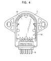
- Fig. 4 is a bottom view of the sensor where a part of the sensor is omitted.
- covers are omitted in order to show the interior of the sensor.
- the rotary position sensor shown in Figs. 1 to 4 detects the amount of depression of a pedal, such as an acceleration pedal and a brake pedal of a vehicle, on the basis of a rotation angle of a rotating member which moves in conjunction with the pedal.
- the rotary position sensor includes a cylindrical housing 1 which is composed of resin and which has a partition wall 10 in the interior thereof; a rotating member 2 which is composed of resin and which is disposed in a storing space S1 between an open end 11 at one end of the housing 1 and the partition wall 10; a support projection 3 which is composed of metal and'which is press fitted into the bottom portion of the rotating member 2 at the rotational center of the rotating member 2; a ringshaped magnet 4 which is fixed on the bottom surface of the rotating member 2 at the peripheral region thereof such that the magnet 4 is in the vicinity of the partition wall 10; a back yoke 5 which is fixed to the rotating member 2 at a position such that the back yoke 5 surrounds the magnet 4 and which serves to prevent leakage of magnetic flux generated by
- a rotating mechanism 20 is constructed of the rotating member 2, the support projection 3, the magnet 4, and the back yoke 5, which are integrated with each other, and is disposed in the storing space S1 of the housing 1 in a rotatable manner.
- the shaft portion 2a of the rotating member 2 is connected to a pedal, which is a detection object, with a wire or the like.
- the electrical circuit component 8 is constructed by mounting various electronic parts, including a giant magnetoresistive element 14 which serves as a magnetoelectric transducer for detecting a change in the magnetic field of the magnet 4, on a circuit board 13 which is fixed to the housing 1 in the storing space S2.
- a signal output from the electrical circuit component 8 is transmitted to an external device (not shown) via a cable 15.
- a gap between the housing 1 and the second cover 9 which closes the open end 12 is sealed by filling the gap with a resin 16 and curing it.
- the partition wall 10 which divides the interior of the housing 1 into the storing space S1 and the storing space S2, projects toward the open end 11 so that a recess 10a is provided as viewed from the open end 12.
- the partition wall 10 has a support member receiver 10b at the central region thereof, and the support member receiver 10b receives the support projection 3 and thereby supports the rotating member 2 in a rotatable manner.
- An insertion hole 10c having approximately the same shape as that of an end portion of the support projection 3 is formed in the support member receiver 10b at the side facing the storing space S1.
- the end portion of the support projection 3 is inserted into the insertion hole 10c and a pointed end of a conical portion of the support projection 3 is brought into contact with the support member receiver 10b at the central position thereof, whereby the support projection 3 is supported in a pivotable manner.
- the rotating member 2 is rotatably retained in the housing 1 in a state such that it is pivotally supported by the central portion (support member receiver 10b) of the partition wall 10 with the support projection 3 therebetween.
- magnetic poles are arranged such that opposite poles face each other across the rotational center of the rotating member 2. Accordingly, the support projection 3 is always placed at the central position between an N-pole and an S-pole of the magnet 4.
- the giant magnetoresistive element 14 included in the electrical circuit component 8 is disposed in the recess 10a, which is formed in the partition wall 10 at the side facing the storing space S2, at a position such that the giant magnetoresistive element 14 faces the support projection 3 across the partition wall 10. Accordingly, the giant magnetoresistive element 14 is placed in a region where the magnetic force applied by the magnet 4 is strong.
- the rotating member 2 when the rotating member 2 is rotated by a predetermined amount in accordance with the movement of the pedal, which is the detection object, the magnetic field of the magnet 4 which is applied to the giant magnetoresistive element 14 changes in accordance with the rotation of the rotating member 2. Accordingly, the output signal from the electrical circuit component 8 changes, so that the amount of depression of the pedal can be determined on the basis of the change in the output signal.
- the rotational driving force of the pedal is removed from the rotating member 2, the rotating member 2 rotates in the reverse direction and returns to the original position due to an elastic restoring force of the return spring 6.
- the interior of the housing 1 is divided into the storing space S1 and the storing space S2 by the partition wall 10.
- the electrical circuit component 8 including the circuit board 13, etc. is disposed in the storing space S2, which is completely separated from the storing space S1 in which the rotating mechanism 20 including the rotating member 2, etc., is disposed. Accordingly, the electrical circuit component 8 can be reliably protected from external water and combustible gas by simply sealing the gap between the second cover 9 and the housing 1 with a small amount of resin 16, and a complex sealing process which is necessary for manufacturing the above-described known sensor can be omitted.
- the rotating mechanism 20 and the return spring 6 disposed in the storing space S1 do not interfere with the electrical circuit component 8 disposed in the storing space S2, the assembly process can be performed easily. Thus, the yield can be increased and the costs can be reduced.
- the support member receiver 10b which receives the support projection 3 and thereby supports the rotating member 2 in a rotatable manner is formed at the central position of the partition wall 10.
- the support member receiver 10b since a supporting structure in which the support projection 3 is pivotally supported by the support member receiver 10b is applied, even when lateral pressure is applied externally, the rotating member 2 can be prevented from being displaced in the lateral direction and only tilts around a pivot center.
- the magnetic field detected by the giant magnetoresistive element 14, which is positioned directly below the pivot center, is affected only slightly.
- the giant magnetoresistive element 14 is disposed in the recess 10a of the partition wall 10 in a region where the magnetic force applied by the magnet 4 is strong, the detection accuracy can be increased. Accordingly, in the above-described rotary position sensor, the rotation angle of the rotating member 2 can always be detected with high accuracy by the giant magnetoresistive element 14 while preventing the rotating member 2 from being displaced in the lateral direction in the detection process.
- the gap between the second cover 9 and the housing 1 is sealed with the resin 16 in the present embodiment
- the gap can also be sealed with an O-ring. In such a case, the sealing process can be omitted, so that the yield can be further increased.
Landscapes
- Physics & Mathematics (AREA)
- General Physics & Mathematics (AREA)
- Transmission And Conversion Of Sensor Element Output (AREA)
- Measurement Of Length, Angles, Or The Like Using Electric Or Magnetic Means (AREA)
Applications Claiming Priority (2)
| Application Number | Priority Date | Filing Date | Title |
|---|---|---|---|
| JP2002067357A JP4191940B2 (ja) | 2002-03-12 | 2002-03-12 | ロータリポジションセンサ |
| JP2002067357 | 2002-03-12 |
Publications (1)
| Publication Number | Publication Date |
|---|---|
| EP1345005A1 true EP1345005A1 (fr) | 2003-09-17 |
Family
ID=27764494
Family Applications (1)
| Application Number | Title | Priority Date | Filing Date |
|---|---|---|---|
| EP03005324A Withdrawn EP1345005A1 (fr) | 2002-03-12 | 2003-03-11 | Capteur d'angle de rotation ayant une structure étanche à l'eau et antidéflagrante |
Country Status (3)
| Country | Link |
|---|---|
| US (1) | US6809513B2 (fr) |
| EP (1) | EP1345005A1 (fr) |
| JP (1) | JP4191940B2 (fr) |
Cited By (10)
| Publication number | Priority date | Publication date | Assignee | Title |
|---|---|---|---|---|
| EP1607913A3 (fr) * | 2003-10-24 | 2007-08-22 | JATCO Ltd | Terminal portable pour ordinateur monte sur un véhicule |
| WO2008112100A3 (fr) * | 2007-03-07 | 2009-03-26 | Cts Corp | Détecteur de position rotatif |
| CN101750100A (zh) * | 2008-12-15 | 2010-06-23 | 东京Cosmos电机株式会社 | 旋转角度传感器 |
| EP2045580A3 (fr) * | 2007-10-03 | 2012-11-14 | Niles Co., Ltd. | Capteur d'angle de rotation sans contact |
| US8450999B2 (en) | 2009-02-17 | 2013-05-28 | Cts Corporation | Rotary position sensor |
| CN101813758B (zh) * | 2009-02-19 | 2013-12-04 | 西门子公司 | 一种磁共振线圈 |
| ITTO20120832A1 (it) * | 2012-09-26 | 2014-03-27 | Elcis Encoder S R L | Trasduttore magnetico antideflagrante |
| US8823366B2 (en) | 2009-11-16 | 2014-09-02 | Cts Corporation | Non-contacting sensor assembly |
| WO2019046526A1 (fr) | 2017-08-30 | 2019-03-07 | Nidec Motor Corporation | Codeur antidéflagrant à sécurité intrinsèque |
| WO2020187980A1 (fr) * | 2019-03-21 | 2020-09-24 | Ipgate Ag | Dispositif d'actionnement pour un système de freinage comprenant un capteur pour déterminer l'angle de rotation et/ou la vitesse de rotation |
Families Citing this family (16)
| Publication number | Priority date | Publication date | Assignee | Title |
|---|---|---|---|---|
| JP4045230B2 (ja) * | 2003-11-04 | 2008-02-13 | 三菱電機株式会社 | 非接触式回転角度検出装置 |
| JP4401868B2 (ja) * | 2004-05-20 | 2010-01-20 | アルプス電気株式会社 | ポジションセンサ |
| US20060001512A1 (en) * | 2004-07-01 | 2006-01-05 | Garcia Jorge L | Rotary control for a communication device |
| DE602005017900D1 (de) * | 2005-10-10 | 2010-01-07 | Infineon Technologies Sensonor | Niederfrequenzempfänger mit Magnetfelddetektor |
| US7382120B2 (en) * | 2006-04-26 | 2008-06-03 | Honeywell International Inc. | Rotary position sensor with rectangular magnet and hall sensors placed in association with the surface of the magnet |
| FR2925749B1 (fr) * | 2007-12-19 | 2010-03-05 | Schneider Electric Ind Sas | Appareil a moyens de reglage sans contact |
| JP4825225B2 (ja) * | 2008-01-09 | 2011-11-30 | 三井金属アクト株式会社 | ドア開閉装置 |
| JP5301864B2 (ja) * | 2008-03-31 | 2013-09-25 | 株式会社ミクニ | 回転位置センサ |
| KR200463586Y1 (ko) * | 2008-09-08 | 2012-11-12 | 한국오므론전장주식회사 | 회전 각도 센서 유닛 |
| JP5750325B2 (ja) * | 2011-07-15 | 2015-07-22 | 山洋電気株式会社 | エンコーダ |
| US9114798B1 (en) * | 2012-12-12 | 2015-08-25 | Hydro-Gear Limited Partnership | Electric actuator for drive apparatus |
| USD712768S1 (en) * | 2013-04-24 | 2014-09-09 | Cateye Co., Ltd. | Rotation detector for a bicycle |
| KR200478693Y1 (ko) | 2014-04-18 | 2015-11-16 | 대성전기공업주식회사 | 로테이션 센서 유니트 |
| WO2018053793A1 (fr) * | 2016-09-23 | 2018-03-29 | Hamlin Electronics (Suzhou) Co., Ltd. | Capteur de position rotatif double intégré |
| DE102017114555A1 (de) * | 2017-06-29 | 2019-01-03 | Endress+Hauser SE+Co. KG | Messsystem |
| DE102019106288B3 (de) * | 2019-03-12 | 2020-03-05 | Sick Stegmann Gmbh | Drehgeber |
Citations (5)
| Publication number | Priority date | Publication date | Assignee | Title |
|---|---|---|---|---|
| US4646011A (en) * | 1983-12-17 | 1987-02-24 | Vdo Adolf Schindling Ag | Electronic angular position transmitter with toroidal core and rotatable magnet |
| EP0482380A2 (fr) * | 1990-10-26 | 1992-04-29 | OTT MESSTECHNIK GmbH & CO. KG | Codeur d'angle, en particulier pour un instrument de mesure d'hydrométrie |
| US5889400A (en) * | 1996-03-08 | 1999-03-30 | Unisia Jecs Corporation | Sensor arranged for detecting angular displacement and direction of valve axle |
| JPH11153404A (ja) * | 1997-11-21 | 1999-06-08 | Teikoku Tsushin Kogyo Co Ltd | 回転角度センサ |
| WO2001077622A2 (fr) * | 2000-04-05 | 2001-10-18 | Rosemount Aerospace Inc. | Capteur d'incidence magnetique |
Family Cites Families (5)
| Publication number | Priority date | Publication date | Assignee | Title |
|---|---|---|---|---|
| JPS5886405A (ja) * | 1981-11-18 | 1983-05-24 | Nec Corp | 角度検出器 |
| NL8502683A (nl) * | 1985-10-01 | 1987-05-04 | Stichting Ct Voor Micro Elektr | Contactloze hoekopnemer. |
| JPH02129813U (fr) * | 1989-03-31 | 1990-10-25 | ||
| JPH09145733A (ja) * | 1995-11-27 | 1997-06-06 | Fujitsu Ten Ltd | 回転速度検出装置 |
| JP2002156245A (ja) * | 2000-11-20 | 2002-05-31 | Aisin Seiki Co Ltd | 非接触式変位センサ |
-
2002
- 2002-03-12 JP JP2002067357A patent/JP4191940B2/ja not_active Expired - Fee Related
-
2003
- 2003-03-07 US US10/383,972 patent/US6809513B2/en not_active Expired - Lifetime
- 2003-03-11 EP EP03005324A patent/EP1345005A1/fr not_active Withdrawn
Patent Citations (5)
| Publication number | Priority date | Publication date | Assignee | Title |
|---|---|---|---|---|
| US4646011A (en) * | 1983-12-17 | 1987-02-24 | Vdo Adolf Schindling Ag | Electronic angular position transmitter with toroidal core and rotatable magnet |
| EP0482380A2 (fr) * | 1990-10-26 | 1992-04-29 | OTT MESSTECHNIK GmbH & CO. KG | Codeur d'angle, en particulier pour un instrument de mesure d'hydrométrie |
| US5889400A (en) * | 1996-03-08 | 1999-03-30 | Unisia Jecs Corporation | Sensor arranged for detecting angular displacement and direction of valve axle |
| JPH11153404A (ja) * | 1997-11-21 | 1999-06-08 | Teikoku Tsushin Kogyo Co Ltd | 回転角度センサ |
| WO2001077622A2 (fr) * | 2000-04-05 | 2001-10-18 | Rosemount Aerospace Inc. | Capteur d'incidence magnetique |
Non-Patent Citations (1)
| Title |
|---|
| PATENT ABSTRACTS OF JAPAN vol. 1999, no. 11 30 September 1999 (1999-09-30) * |
Cited By (15)
| Publication number | Priority date | Publication date | Assignee | Title |
|---|---|---|---|---|
| EP1607913A3 (fr) * | 2003-10-24 | 2007-08-22 | JATCO Ltd | Terminal portable pour ordinateur monte sur un véhicule |
| WO2008112100A3 (fr) * | 2007-03-07 | 2009-03-26 | Cts Corp | Détecteur de position rotatif |
| EP2045580A3 (fr) * | 2007-10-03 | 2012-11-14 | Niles Co., Ltd. | Capteur d'angle de rotation sans contact |
| CN101750100B (zh) * | 2008-12-15 | 2014-01-08 | 东京Cosmos电机株式会社 | 旋转角度传感器 |
| CN101750100A (zh) * | 2008-12-15 | 2010-06-23 | 东京Cosmos电机株式会社 | 旋转角度传感器 |
| US8450999B2 (en) | 2009-02-17 | 2013-05-28 | Cts Corporation | Rotary position sensor |
| US8692544B2 (en) | 2009-02-17 | 2014-04-08 | Cts Corporation | Rotary position sensor |
| US9297637B2 (en) | 2009-02-17 | 2016-03-29 | Cts Corporation | Rotary position sensor |
| CN101813758B (zh) * | 2009-02-19 | 2013-12-04 | 西门子公司 | 一种磁共振线圈 |
| US8823366B2 (en) | 2009-11-16 | 2014-09-02 | Cts Corporation | Non-contacting sensor assembly |
| ITTO20120832A1 (it) * | 2012-09-26 | 2014-03-27 | Elcis Encoder S R L | Trasduttore magnetico antideflagrante |
| EP2713141A3 (fr) * | 2012-09-26 | 2015-06-17 | Elcis Encoder S.R.L. | Capteur magnétique protégé contre les explosions |
| WO2019046526A1 (fr) | 2017-08-30 | 2019-03-07 | Nidec Motor Corporation | Codeur antidéflagrant à sécurité intrinsèque |
| EP3676916A4 (fr) * | 2017-08-30 | 2021-04-28 | Nidec Motor Corporation | Codeur antidéflagrant à sécurité intrinsèque |
| WO2020187980A1 (fr) * | 2019-03-21 | 2020-09-24 | Ipgate Ag | Dispositif d'actionnement pour un système de freinage comprenant un capteur pour déterminer l'angle de rotation et/ou la vitesse de rotation |
Also Published As
| Publication number | Publication date |
|---|---|
| JP4191940B2 (ja) | 2008-12-03 |
| US20030173954A1 (en) | 2003-09-18 |
| JP2003269992A (ja) | 2003-09-25 |
| US6809513B2 (en) | 2004-10-26 |
Similar Documents
| Publication | Publication Date | Title |
|---|---|---|
| US6809513B2 (en) | Rotary position sensor having waterproof, explosion-protective structure | |
| CN108528213B (zh) | 踏板装置及其制备方法 | |
| US7285952B1 (en) | Rotation angle detecting device | |
| JP2551705Y2 (ja) | 車輪用軸受の回転速度検出装置 | |
| EP2192037B1 (fr) | Commande de manette intégrant un capteur de position angulaire | |
| US6703826B2 (en) | Rotation detector having improved vibration characteristics | |
| JPH11153404A (ja) | 回転角度センサ | |
| JP3026265B1 (ja) | 回転検出装置 | |
| US4931719A (en) | Hall-effect sensor arrangement | |
| JP4720159B2 (ja) | 液面検出装置 | |
| KR20180102001A (ko) | 페달 장치 및 그 제조 방법 | |
| CN103547891A (zh) | 位置检测装置 | |
| JP2000241195A (ja) | 回転検出装置 | |
| JP2009098005A (ja) | 位置検出器 | |
| JPH04324302A (ja) | スロットルポジションセンサ | |
| JP2005091275A (ja) | 回転角センサ | |
| JP3906834B2 (ja) | 回転検出装置 | |
| JP2006214985A (ja) | ポテンショメータ | |
| KR100663382B1 (ko) | 차량용 전자식 가속페달 | |
| JP2002181509A (ja) | 位置検出装置 | |
| JP4151076B2 (ja) | 回転伝達装置 | |
| JP2005106780A (ja) | 回転角センサ | |
| JP3693157B2 (ja) | 回転検出装置 | |
| JP2006153615A (ja) | 液面検出装置 | |
| JP2019113386A (ja) | 回転検出装置 |
Legal Events
| Date | Code | Title | Description |
|---|---|---|---|
| PUAI | Public reference made under article 153(3) epc to a published international application that has entered the european phase |
Free format text: ORIGINAL CODE: 0009012 |
|
| AK | Designated contracting states |
Kind code of ref document: A1 Designated state(s): AT BE BG CH CY CZ DE DK EE ES FI FR GB GR HU IE IT LI LU MC NL PT RO SE SI SK TR |
|
| AX | Request for extension of the european patent |
Extension state: AL LT LV MK |
|
| 17P | Request for examination filed |
Effective date: 20030925 |
|
| AKX | Designation fees paid |
Designated state(s): DE FR GB SE |
|
| 17Q | First examination report despatched |
Effective date: 20070514 |
|
| STAA | Information on the status of an ep patent application or granted ep patent |
Free format text: STATUS: THE APPLICATION HAS BEEN WITHDRAWN |
|
| 18W | Application withdrawn |
Effective date: 20091022 |