EP1345024A1 - Procédé et dispositif permettant la mesure polarimétrique des coefficients de la matrice de Mueller de l'ultraviolet lointain au domaine visible - Google Patents
Procédé et dispositif permettant la mesure polarimétrique des coefficients de la matrice de Mueller de l'ultraviolet lointain au domaine visible Download PDFInfo
- Publication number
- EP1345024A1 EP1345024A1 EP02290611A EP02290611A EP1345024A1 EP 1345024 A1 EP1345024 A1 EP 1345024A1 EP 02290611 A EP02290611 A EP 02290611A EP 02290611 A EP02290611 A EP 02290611A EP 1345024 A1 EP1345024 A1 EP 1345024A1
- Authority
- EP
- European Patent Office
- Prior art keywords
- polarimetric
- sample
- far ultraviolet
- chambers
- light beam
- Prior art date
- Legal status (The legal status is an assumption and is not a legal conclusion. Google has not performed a legal analysis and makes no representation as to the accuracy of the status listed.)
- Withdrawn
Links
- 238000000034 method Methods 0.000 title claims abstract description 26
- 238000005259 measurement Methods 0.000 title claims abstract description 25
- 230000003595 spectral effect Effects 0.000 title claims abstract description 14
- 239000011159 matrix material Substances 0.000 title claims abstract description 13
- 239000007789 gas Substances 0.000 claims abstract description 40
- 230000005284 excitation Effects 0.000 claims abstract description 28
- 238000001514 detection method Methods 0.000 claims abstract description 27
- 238000004458 analytical method Methods 0.000 claims abstract description 25
- 230000003287 optical effect Effects 0.000 claims description 19
- 238000005086 pumping Methods 0.000 claims description 18
- 229910001635 magnesium fluoride Inorganic materials 0.000 claims description 12
- 238000000572 ellipsometry Methods 0.000 claims description 11
- 230000006870 function Effects 0.000 claims description 10
- 238000010438 heat treatment Methods 0.000 claims description 10
- IJGRMHOSHXDMSA-UHFFFAOYSA-N Atomic nitrogen Chemical compound N#N IJGRMHOSHXDMSA-UHFFFAOYSA-N 0.000 claims description 8
- 238000012545 processing Methods 0.000 claims description 8
- 230000005855 radiation Effects 0.000 claims description 7
- 230000008878 coupling Effects 0.000 claims description 5
- 238000010168 coupling process Methods 0.000 claims description 5
- 238000005859 coupling reaction Methods 0.000 claims description 5
- 238000012544 monitoring process Methods 0.000 claims description 4
- 239000000284 extract Substances 0.000 claims description 3
- 230000003071 parasitic effect Effects 0.000 claims description 3
- 230000001105 regulatory effect Effects 0.000 claims description 3
- 239000012780 transparent material Substances 0.000 claims description 2
- 238000002211 ultraviolet spectrum Methods 0.000 claims description 2
- 239000000523 sample Substances 0.000 description 56
- 239000010410 layer Substances 0.000 description 17
- VYPSYNLAJGMNEJ-UHFFFAOYSA-N Silicium dioxide Chemical compound O=[Si]=O VYPSYNLAJGMNEJ-UHFFFAOYSA-N 0.000 description 12
- XLYOFNOQVPJJNP-UHFFFAOYSA-N water Substances O XLYOFNOQVPJJNP-UHFFFAOYSA-N 0.000 description 7
- 229910052681 coesite Inorganic materials 0.000 description 6
- 229910052906 cristobalite Inorganic materials 0.000 description 6
- 239000000377 silicon dioxide Substances 0.000 description 6
- 229910052682 stishovite Inorganic materials 0.000 description 6
- 229910052905 tridymite Inorganic materials 0.000 description 6
- 229910052757 nitrogen Inorganic materials 0.000 description 3
- YZCKVEUIGOORGS-OUBTZVSYSA-N Deuterium Chemical compound [2H] YZCKVEUIGOORGS-OUBTZVSYSA-N 0.000 description 2
- CBENFWSGALASAD-UHFFFAOYSA-N Ozone Chemical compound [O-][O+]=O CBENFWSGALASAD-UHFFFAOYSA-N 0.000 description 2
- XUIMIQQOPSSXEZ-UHFFFAOYSA-N Silicon Chemical compound [Si] XUIMIQQOPSSXEZ-UHFFFAOYSA-N 0.000 description 2
- XAGFODPZIPBFFR-UHFFFAOYSA-N aluminium Chemical compound [Al] XAGFODPZIPBFFR-UHFFFAOYSA-N 0.000 description 2
- 229910052782 aluminium Inorganic materials 0.000 description 2
- QVGXLLKOCUKJST-UHFFFAOYSA-N atomic oxygen Chemical compound [O] QVGXLLKOCUKJST-UHFFFAOYSA-N 0.000 description 2
- 230000005540 biological transmission Effects 0.000 description 2
- 238000012512 characterization method Methods 0.000 description 2
- 239000013078 crystal Substances 0.000 description 2
- 229910052805 deuterium Inorganic materials 0.000 description 2
- 230000003993 interaction Effects 0.000 description 2
- 239000000463 material Substances 0.000 description 2
- 239000000203 mixture Substances 0.000 description 2
- 239000001301 oxygen Substances 0.000 description 2
- 229910052760 oxygen Inorganic materials 0.000 description 2
- 230000008569 process Effects 0.000 description 2
- 229910052710 silicon Inorganic materials 0.000 description 2
- 239000010703 silicon Substances 0.000 description 2
- 229910017872 a-SiO2 Inorganic materials 0.000 description 1
- 238000010521 absorption reaction Methods 0.000 description 1
- WUKWITHWXAAZEY-UHFFFAOYSA-L calcium difluoride Chemical compound [F-].[F-].[Ca+2] WUKWITHWXAAZEY-UHFFFAOYSA-L 0.000 description 1
- 229910001634 calcium fluoride Inorganic materials 0.000 description 1
- 230000015556 catabolic process Effects 0.000 description 1
- 230000008859 change Effects 0.000 description 1
- 239000013626 chemical specie Substances 0.000 description 1
- 239000011247 coating layer Substances 0.000 description 1
- 230000000295 complement effect Effects 0.000 description 1
- 238000006731 degradation reaction Methods 0.000 description 1
- 230000001419 dependent effect Effects 0.000 description 1
- 238000013461 design Methods 0.000 description 1
- 239000003989 dielectric material Substances 0.000 description 1
- 238000010891 electric arc Methods 0.000 description 1
- 230000005670 electromagnetic radiation Effects 0.000 description 1
- 238000011066 ex-situ storage Methods 0.000 description 1
- 238000002474 experimental method Methods 0.000 description 1
- 238000000605 extraction Methods 0.000 description 1
- 238000007429 general method Methods 0.000 description 1
- 238000005286 illumination Methods 0.000 description 1
- 238000011065 in-situ storage Methods 0.000 description 1
- 230000031700 light absorption Effects 0.000 description 1
- 238000004377 microelectronic Methods 0.000 description 1
- 238000012986 modification Methods 0.000 description 1
- 230000004048 modification Effects 0.000 description 1
- 238000000711 polarimetry Methods 0.000 description 1
- 239000011241 protective layer Substances 0.000 description 1
- 230000004044 response Effects 0.000 description 1
- 239000004065 semiconductor Substances 0.000 description 1
- 238000001228 spectrum Methods 0.000 description 1
- 239000011800 void material Substances 0.000 description 1
Images




Classifications
-
- G—PHYSICS
- G01—MEASURING; TESTING
- G01N—INVESTIGATING OR ANALYSING MATERIALS BY DETERMINING THEIR CHEMICAL OR PHYSICAL PROPERTIES
- G01N21/00—Investigating or analysing materials by the use of optical means, i.e. using sub-millimetre waves, infrared, visible or ultraviolet light
- G01N21/17—Systems in which incident light is modified in accordance with the properties of the material investigated
- G01N21/21—Polarisation-affecting properties
- G01N21/211—Ellipsometry
Definitions
- the invention relates to a method of polarimetric measurement of the representative parameters of a sample and a polarimetric system for analysing such a sample.
- Ellipsometry is a powerful non invasive probe in which reflectance data are measured by reflecting electromagnetic radiation from a sample. Briefly, the surface of a studied sample is illuminated by a photon beam that is reflected and the polarisation state of the reflected beam (that may be transmitted) is compared to that of the incident beam.
- the polarisation vector E of a beam is generally represented by its projections Es and Ep, respectively perpendicular and parallel to the incidence plane.
- the aim therefore is to measure the independent parameters ⁇ and ⁇ for a given surface.
- Polarimetric systems enable to measure all the polarisation components of light in any medium.
- the polarisation state of light can be represented completely by a fourth dimension vector, called the Stokes light vector (S).
- S Stokes light vector
- the Stokes vector consists of the I, Q, U and V coordinates, respectively representing the mean intensities of the four different polarisation states.
- the interaction of light with any medium can then be represented by a matrix, so-called, the Mueller matrix, of dimensions 4 x 4 with therefore 16 coefficients.
- this matrix method reduces to a simple 2 x 2 matrix, so called, the Jones matrix.
- FUV Far ultraviolet
- GaN, C, 7-9 wide band gap semiconductor
- high-k dielectrics that are not measurable with current polarimetric systems and the capability to perform optical measurements at the photon wavelength of the lasers currently used in microelectronic processes (157 nm).
- the purpose of the invention is hence to remedy the short comings mentioned above and to propose a polarimetric system having one or more of the following features and advantages : namely, a fast data acquisition, be usable for measurements in real time, offering a wide photon energy range in the far ultraviolet and a simple and compact design.
- the invention has as an objective a method for the measurement of the representative parameters of a sample, this method being at once precise, rapid and easy to implement.
- the invention concerns a method of polarimetric measurement of a sample, represented by the coefficients of a Mueller matrix, in which the sample located inside an air tight chamber is illuminated by a polarised incident light beam produced by a polarisation state generator (PSG), said beam being reflected by the sample, analysed by a polarisation state detector (PSD) and then measured by detections means, said PSG, sample, PSD and detection means being located in at least an air tight chamber.
- PSG polarised incident light beam produced by a polarisation state generator
- PSD polarisation state detector
- the polarimetric system according to the invention shown in Fig. 1 contains an excitation section 1 emitting a light beam 2, a sample holder 3 and an analysis section 4.
- the excitation section 1 comprises a polarisation state generator 5 (PSG) through which passes the light beam 2.
- First optical means 6 focuses said beam 2 onto the sample 7 located on a sample-holder 3.
- the beam 2 reflects off the sample surface 8 and passes through the analysis section 4.
- the analysis section comprises a polarisation state detector 9 (PSD) or polarimeter and detection means 10 for detecting the light beam 2.
- the polarimetric system comprises as well a monochromator 11 which is located in a first embodiment before the light beam 2 enters the polarisation state generator 5. In a second embodiment, it is located after it exits the polarisation state detector 9.
- a slit 12 is positioned at the entrance of said monochromator 11 and focusing means 13 focuses the beam onto the entrance slit 12.
- the focusing means 13 contains a MgF 2 lens or an equivalent far ultraviolet transparent lens.
- the invention regards as well conventional ellipsometry that is a special case of polarimetry for isotropic layers with smooth interfaces.
- the ellipsometric system shown in Fig.2, contains an excitation section 1 emitting a light beam 2, a sample holder 3 and an analysis section 4.
- the excitation section 1 comprises a polariser 5 which polarises the incident beam 2.
- the polarisation state of the light beam 2 emerging from the polariser 5 is hence precisely known.
- the light beam then goes through a phase modulator 14, preferably photoelastic, which modulates the beam 2 at a frequency ⁇ .
- the photoelastic modulator 14 is known to have advantageously a wide optic window.
- the beam 2 After going through the phase modulator 14, the beam 2 falls onto first optical means 6 which focuses said beam 2 onto the sample 7 located on a sample-holder 3.
- the sample holder 3 contains preferably means for tilting said sample holder.
- the light beam 2 emitted by the excitation section 1 has a direction and sense of propagation which defines an incident plane.
- the incidence angle of the light beam 2 on the sample surface 8 is defined as the angle at which the focused beam strikes the sample surface 8 with respect to the normal to the surface 8.
- a beam 2 with normal incidence at the sample surface 8 has an incidence angle of zero degree.
- the angle of incidence of the beam can be advantageously varied.
- the purpose of the focusing beam is to obtain a small spot on the sample, i.e. a compact spot with preferably dimensions inferior to a few tenths of mm 2 . This spot should provide a lateral resolution sufficient to map the sample surface 8.
- the beam 2 reflected by the sample surface 8 falls onto the analysis section 4.
- Said analysis section 4 comprises an analyser 9 and second optical means 15 coupling said analyser 9 and detection means 10.
- the first and second optical means 6, 15 are preferably concave mirrors.
- a protective layer such as a MgF 2 layer is deposited on the surface of said mirrors.
- the signal detected by the detection means 10 is then sent to a treatment unit 16.
- the treatment unit 16 contains a data signal processor and a computer.
- the data signal processor is equipped with an analog-digital converter (ADC) and a memory of the FIFO type.
- ADC analog-digital converter
- the ellipsometric system comprises as well a monochromator 11.
- said monochromator is located in the excitation section 1.
- the monochromator 11 is then located before, in the sense of propagation of the light beam, the polariser 5.
- the monochromator 11 is located in the analysis section 4 between the analyser 9 and the detection means 10.
- a slit 12 is positioned at the entrance of said monochromator 11 and focusing means 13 focuses the beam onto the entrance slit 12.
- the focusing means 13 contains a MgF 2 lens.
- the polarimetric system comprises at least an air tight chamber 17, said chambers 17 containing said excitation section 1, said analysis section 4 and the sample-holder 3.
- the tilting of the sample holder 3 is controlled by external means to the chamber 17 containing said sample holder.
- the chambers 17 are interconnected to form a unique vessel.
- the light beam 2 emitted by the excitation section is in the spectral range from the far ultraviolet to the visible.
- the far ultraviolet region of the electromagnetic spectrum the photon energy region extending from 6 eV to 10.3 eV.
- the light beam propagates through the excitation section 1 up to through the analysis section 4 under a low partial pressure of far ultraviolet highly absorbing gases.
- a low partial pressure a partial pressure of far ultraviolet highly absorbing gases ranging from 10 -4 to 10 -3 mbar.
- the low partial pressure of far ultraviolet absorbing gases inside said air tight chambers 17 is preferably obtained either by air evacuation using a pumping station 18 or by rinsing air tight chamber 17 with a far ultraviolet non absorbing gas such as nitrogen N 2 . It can be obtained as well by air evacuation using a pumping station 18 and then refilling of said chambers with a far ultraviolet non absorbing gas such as nitrogen N 2 .
- the chambers contain pressure monitoring means 19 to monitor the vacuum realised by the pumping station 18.
- the pumping station 18 contains at least a primary pump such as a rotary pump,... But other or complementary vacuum equipments are possible like turbomolecular pumps.
- the monitoring means 19 comprises for example manometers and cold cathode gauges.
- polarimetric measurements can be performed either under the previously described vacuum conditions or in a far UV non absorbing environment achieved by refilling said chamber 17 with FUV non absorbing gases up to an overatmospheric pressure.
- said chamber 17 When working under vacuum conditions, said chamber 17 must be filled with FUV non absorbing gases for sample modification purpose.
- the polarimetric system thus comprises a source 20 of far ultraviolet non absorbing gases and means 21 for connecting and leaking said gases into the polarimetric system.
- the chambers are equipped with heating means 22.
- the chambers 17 are baked in vacuum to get rid of the water film covering the inner walls of the chambers. This water film appears at each exposition of said chambers to air, for example when changing the sample 7. Without baking of the chambers, the water molecules responsible for a large amount of the far ultraviolet light absorption would slowly desorb from the inner walls of the chamber maintaining inside the chambers a remanent water vapour pressure.
- the ellipsometric system contains control sensors 23 for measuring the temperature of the chambers 17 at various locations and control means 24 for regulating the temperature of the heating means within a predetermined temperature range.
- the heating means 22 comprises heating tapes and the control means 24 contains temperature gauges.
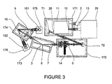
- Figure 3 shows a particular embodiment of the polarimetric system according to the invention.
- the light beam 2 emitted by the excitation section 1 is generated by a light source 25 containing a water-cooled high-pressure arc-discharge deuterium lamp.
- the photon energies of the light beam 2 range from 1.5 to 10.3 eV.
- the light beam 2 goes firstly through a monochromator 11 covering the spectral range from 1 to 9.5 eV.
- Said monochromator 11 has an exit slit 26 of 0.5 mm which provides an outgoing beam of 2 nm of bandwidth.
- a 0.5 mm slit 12 is set at the entrance of this device 11.
- the light beam 2 produced by the deuterium lamp 25 having a considerable divergence, a MgF 2 lens 13 (f 50 mm), is located between the source 25 and the monochromator 11 to focus the light beam 2 onto said entrance slit 12.
- the light beam goes through a polariser 5, a phase-modulator 14 and optical means 71, 72 to focus said beam on the sample surface 8.
- the light beam 2 leaving the monochromator 11 is linearly polarised by the polariser 5.
- the polariser 5 is a MgF 2 Rochon polariser with a principal axis oriented at 45° with respect to the principal axis of the phase modulator 14.
- the phase modulator 14 is a photoelastic modulator with a CaF 2 active optical element working at a frequency of 50 kHz.
- two aluminum concave mirrors 71, 72 are located between the monochromator 11 and the polariser 5, with focal lengths of 150 and 250 mm respectively. Both mirrors 71, 72 are coated with a thin MgF 2 layer (about 20 ⁇ thick) in order to prevent time degradation.
- the detection means 10 comprises two detectors 101, 102.
- the first detector 101 is a photomultiplier that probes radiation in the spectral range from 1 to 6 eV.
- the second detector 102 is a solar blind photomultiplier optimised to detect radiation in the 5.5 to 12 eV energy range.
- a diaphragm Since transmission of the light beam through a Rochon polariser 9 splits said beam into two beams having a relative polarisation phase difference of 90°, a diaphragm is located in front of the active area of each detector 101, 102. This diaphragm avoids simultaneous detection of both beams. After detection, the signal is sent to a treatment unit.
- Chamber 171 contains the monochromator 11 and a first concave mirror 71.
- Chamber 172 includes a second concave mirror 72, the polariser 5 and the photoelastic modulator 14.
- Chamber 173 contains the sample holder 3 fixed to a chamber wall. Under vacuum conditions, the chamber walls can present small deformations due to the pressure differences that can then, perturb the beam 2 alignment.
- Chamber 174 contains the analyser 9 and the mirror 15 used to focus the light beam onto the selected detector 10.
- Chambers 175 and 176 contain each one, the corresponding photomultiplier and the related electronics.
- the low partial pressure of highly absorbing gases such as water vapour, oxygen, ozone, ... is first realised by pumping down the volume constituted by the six chambers 171, 172, ..., 176 with a pumping unit 18. Then the ellipsometric experiments can be performed either under these vacuum conditions or by filling the chambers 171, 172, ..., 176 with FUV non absorbing gases up to an overatmospheric pressure. If measurements are performed under vacuum, replacement of the sample requires the filling of said chambers with FUV non absorbing gas such as Nitrogen. When the replacement is performed a pumping stage is necessary to restore vacuum conditions. Working under overpressure requires lower pressure for sample replacement, then pumping down to evacuate the absorbing species and finally refilling the chamber up to the working overpressure.
- highly absorbing gases such as water vapour, oxygen, ozone, ...
- the specifications of the polarimetric system according to the invention are provided for illustrative purposes only and should not be used to unduly limit the scope of the present invention.
- the polarimetric system is not limited to ex situ measurements, i.e. the sample to analyse has been prepared in an external set-up but can be adapted for in situ operation.
- the sample holder 3 can be substituted by a process reactor chamber.
- the invention also concerns a method of polarimetric measurement of the representative parameters of a sample 7.
- the sample 7 located inside a first air tight chamber 17 is illuminated by a polarised incident light beam 2 produced by a polarisation state generator (PSG).
- PSG polarisation state generator
- the beam is analysed by a polarisation state detector (PSD) 9 and then measured by detections means 10.
- Said polarisation state generator 5, polarisation state detector 9 and detection means 10 are located either in the said first chamber or at least in a second air tight chamber.
- all the chambers 17 are interconnected to form a unique volume where the beam propagates.
- This evacuation is in a first embodiment achieved by realising an overpressure of far ultraviolet non absorbing gas inside the said chambers 17. In a second embodiment, this is achieved by pumping down the said chambers 17. In a third embodiment, one evacuates far ultraviolet highly absorbing gases by pumping down said chambers 17 and then refills said chambers 17 with far ultraviolet non absorbing gas.
- the energy range of the incident light beam is between 1.5 and 9.5 eV.
- the parameters representative of the sample are measured by phase modulated ellipsometry.
- the behaviour of the optical elements can be represented by means of a 2 x 2 Jones matrix
- I is the overall beam intensity transmitted through the ellipsometric system
- the intensities I 0 , I s , and I c are functions of the position of the optical elements and the sample characterisation.
- the amplitudes of the n-th harmonic, A n are considered to be much more smaller than A 1 , the amplitude at the fundamental modulation frequency ⁇ .
- the modulation frequency is between 30 and 60kHz
- a first Fourier-transform processing means analyses the signal I(t) into Fourrier components, S 0 (dc), S 1 , S 2 at frequency ⁇ and at frequency 2 ⁇ .
- the ellipsometric angles ⁇ and ⁇ are trigonometric functions of the three intensities lo, Is, Ic which are related to the measured harmonics S 0 , S 1 , S 2 according to the following relation:
- the coefficients T 1 and T 2 account for the transmission efficiency of the harmonics ⁇ and 2 ⁇ by the detection system, and the other coefficients represent the coupling between the three Fourier components of the detected signal.
- the value of those coefficients is found to slightly depend on the photon energy of the radiation beam. Therefore, they can be considered as constant or linearly dependent with the photon energy. Accordingly, the value of T 1 , T 2 , C c,0, C c, ⁇ and C s,2 ⁇ is estimated from the corresponding zero or first order polynomial that best fits the experimental values of those coefficients resulting from the calibration. However, with an ellipsometer using far ultraviolet light source, a stronger spectral dependence of the coefficients is measured. Preferably, a fourth degree polynomial allows to evaluate the calibration coefficients.
- third processing means produces the value ⁇ and ⁇ from I 0 , I s , and I c according to simple trigonometric formulae.
- the polarimetric system and the method of polarimetric measurement of the representative parameters of a sample according to the invention have been the object of various implementations whose following example(s) demonstrate(s) the quality of the results obtained.
- FIG. 4 shows the experimental (squares) and best fitted (solid line) values obtained as a function of the incident photon energy 29 for the ellipsometric angles ⁇ 27 and ⁇ 28.
- the experimental values were simulated considering the wafer as a c - Si semi-infinite media coated by a thin rough native oxide layer.
- Said coating layer is composed of a mixture of voids and a-SiO 2 .
- the fitting parameters were the angle of incidence and the thickness of the native oxide layer.
- the volume fraction of the void inclusions was kept constant at 35 % to avoid correlation with the rough layer thickness.
- the resulting best fitted values for the rough native oxide layer thickness and the angle of incidence were 16 ⁇ 3 ⁇ and 73.7 ⁇ 0.1° respectively.
- the method has also been implemented to study a thin SiO 2 film thermally grown on a c - Si wafer.
- the optical response of this sample has been modelled assuming a bilayer structure deposited on a semi-infinite c - Si medium.
- the layer in contact with the c - Si media is supposed to be composed of pure SiO 2 .
- the second layer, located on top, accounts for the possible roughness of the oxide. The thickness of those two layers was used as the fitting parameters.
- Figure 5 shows the experimental (squares) and simulated values (solid line) of ⁇ 27 and ⁇ 28 using the best fitted values of 6270 ⁇ 10 ⁇ for the pure SiO 2 layer and 70 ⁇ 5 ⁇ for the rough layer, giving a total thickness for the thermal SiO 2 film of 6340 ⁇ 15 ⁇ .
- This sample has been measured independently using conventional VIS-UV ellipsometry and the experimental values were fitted considering the same bilayer model.
- the resulting best fitted total thickness for the thermal SiO 2 film was 6330 ⁇ 10 ⁇ , which is consistent within the error interval with the value determined with far ultraviolet ellipsometry, thus confirming the performance of this ellipsometric technique.
Landscapes
- Physics & Mathematics (AREA)
- Health & Medical Sciences (AREA)
- Life Sciences & Earth Sciences (AREA)
- Chemical & Material Sciences (AREA)
- Analytical Chemistry (AREA)
- Biochemistry (AREA)
- General Health & Medical Sciences (AREA)
- General Physics & Mathematics (AREA)
- Immunology (AREA)
- Pathology (AREA)
- Investigating Or Analysing Materials By Optical Means (AREA)
- Spectrometry And Color Measurement (AREA)
Priority Applications (5)
| Application Number | Priority Date | Filing Date | Title |
|---|---|---|---|
| EP02290611A EP1345024A1 (fr) | 2002-03-11 | 2002-03-11 | Procédé et dispositif permettant la mesure polarimétrique des coefficients de la matrice de Mueller de l'ultraviolet lointain au domaine visible |
| PCT/EP2003/002480 WO2003076910A1 (fr) | 2002-03-11 | 2003-03-11 | Systeme polarimetrique et procede de mesure polarimetrique des parametres representatifs d'un echantillon |
| JP2003575084A JP2005520132A (ja) | 2002-03-11 | 2003-03-11 | サンプルの特性パラメータを偏光測定する方法と装置 |
| US10/507,280 US20050105088A1 (en) | 2002-03-11 | 2003-03-11 | Method and device for polarimetric measurement of the mueller matrix coefficients of a sample in the far ultraviolet to visible spectral range |
| AU2003212332A AU2003212332A1 (en) | 2002-03-11 | 2003-03-11 | Method and device for polarimetric measurement of the mueller matrix coefficients of a sample in the far ultraviolet to visible spectral range |
Applications Claiming Priority (1)
| Application Number | Priority Date | Filing Date | Title |
|---|---|---|---|
| EP02290611A EP1345024A1 (fr) | 2002-03-11 | 2002-03-11 | Procédé et dispositif permettant la mesure polarimétrique des coefficients de la matrice de Mueller de l'ultraviolet lointain au domaine visible |
Publications (1)
| Publication Number | Publication Date |
|---|---|
| EP1345024A1 true EP1345024A1 (fr) | 2003-09-17 |
Family
ID=27763454
Family Applications (1)
| Application Number | Title | Priority Date | Filing Date |
|---|---|---|---|
| EP02290611A Withdrawn EP1345024A1 (fr) | 2002-03-11 | 2002-03-11 | Procédé et dispositif permettant la mesure polarimétrique des coefficients de la matrice de Mueller de l'ultraviolet lointain au domaine visible |
Country Status (5)
| Country | Link |
|---|---|
| US (1) | US20050105088A1 (fr) |
| EP (1) | EP1345024A1 (fr) |
| JP (1) | JP2005520132A (fr) |
| AU (1) | AU2003212332A1 (fr) |
| WO (1) | WO2003076910A1 (fr) |
Cited By (1)
| Publication number | Priority date | Publication date | Assignee | Title |
|---|---|---|---|---|
| CN113281256A (zh) * | 2021-05-31 | 2021-08-20 | 中国科学院长春光学精密机械与物理研究所 | 穆勒矩阵测量装置及其测量方法 |
Families Citing this family (7)
| Publication number | Priority date | Publication date | Assignee | Title |
|---|---|---|---|---|
| FR2886015B1 (fr) * | 2005-05-18 | 2007-07-13 | Commissariat Energie Atomique | Procede de mesure de la porosite par ellipsometrie et dispositif mettant en oeuvre un tel procede |
| US7557918B1 (en) | 2006-04-05 | 2009-07-07 | Itt Manufacturing Enterprises, Inc. | Spectral polarimetric image detection and analysis methods and apparatus |
| RU2583959C1 (ru) * | 2015-03-24 | 2016-05-10 | Федеральное государственное бюджетное учреждение науки институт физики им. Л.В. Киренского Сибирского отделения Российской академии наук | Способ определения матрицы мюллера |
| CN107490547B (zh) * | 2017-07-26 | 2020-03-27 | 天津大学 | 一种Mueller矩阵型椭偏仪椭偏参数测量的优化方法 |
| US10886155B2 (en) * | 2019-01-16 | 2021-01-05 | Applied Materials, Inc. | Optical stack deposition and on-board metrology |
| CN111307722B (zh) * | 2019-11-29 | 2021-04-16 | 北京理工大学 | 一种多功能Stokes-Mueller矩阵成像偏振仪的标定方法 |
| CN113310907B (zh) * | 2021-06-09 | 2022-07-05 | 华中科技大学 | 一种磁性椭偏测量装置 |
Citations (3)
| Publication number | Priority date | Publication date | Assignee | Title |
|---|---|---|---|---|
| US5237447A (en) * | 1992-08-27 | 1993-08-17 | The United States Of America As Represented By The Administrator Of The National Aeronautics And Space Administration | Alkali metal for ultraviolet band-pass filter |
| US5666200A (en) * | 1995-02-27 | 1997-09-09 | Instruments S.A. | Method of ellipsometric measurement, an ellipsometer and device for controlling the carrying out of layers using such method and apparatus |
| US6307627B1 (en) * | 1997-09-22 | 2001-10-23 | Hdi Instrumentation | Optical measurement system using polarized light |
Family Cites Families (5)
| Publication number | Priority date | Publication date | Assignee | Title |
|---|---|---|---|---|
| US6804004B1 (en) * | 1998-03-03 | 2004-10-12 | J. A. Woollam Co., Inc | Multiple-element lens systems and methods for uncorrelated evaluation of parameters in parameterized mathematical model equations for lens retardance, in ellipometry and polarimetry |
| DE19717488C2 (de) * | 1997-04-25 | 2003-05-15 | Baumer Optronic Gmbh | Vorrichtung zur Inspektion der Oberfläche von Objekten |
| US5956147A (en) * | 1997-06-13 | 1999-09-21 | Lockheed Martin Energy Research Corporation | Two modulator generalized ellipsometer for complete mueller matrix measurement |
| ATE480005T1 (de) * | 1999-06-11 | 2010-09-15 | Applied Biosystems Llc | Maldi ionenquelle mit gasimpuls, vorrichtung und verfahren zur ermittlung des molekulargewichtes labilen moleküle |
| US6982792B1 (en) * | 2000-03-21 | 2006-01-03 | J.A. Woollam Co. Inc | Spectrophotometer, ellipsometer, polarimeter and the like systems |
-
2002
- 2002-03-11 EP EP02290611A patent/EP1345024A1/fr not_active Withdrawn
-
2003
- 2003-03-11 US US10/507,280 patent/US20050105088A1/en not_active Abandoned
- 2003-03-11 JP JP2003575084A patent/JP2005520132A/ja active Pending
- 2003-03-11 AU AU2003212332A patent/AU2003212332A1/en not_active Abandoned
- 2003-03-11 WO PCT/EP2003/002480 patent/WO2003076910A1/fr not_active Ceased
Patent Citations (3)
| Publication number | Priority date | Publication date | Assignee | Title |
|---|---|---|---|---|
| US5237447A (en) * | 1992-08-27 | 1993-08-17 | The United States Of America As Represented By The Administrator Of The National Aeronautics And Space Administration | Alkali metal for ultraviolet band-pass filter |
| US5666200A (en) * | 1995-02-27 | 1997-09-09 | Instruments S.A. | Method of ellipsometric measurement, an ellipsometer and device for controlling the carrying out of layers using such method and apparatus |
| US6307627B1 (en) * | 1997-09-22 | 2001-10-23 | Hdi Instrumentation | Optical measurement system using polarized light |
Non-Patent Citations (2)
| Title |
|---|
| BREVILLON B: "PHASE MODULATED ELLIPSOMETRY FROM THE ULTRAVIOLET TO THE INFRARED: IN SITU APPLICATION TO THE GROWTH OF SEMICONDUCTORS", PROGRESS IN CRYSTAL GROWTH AND CHARACTERIZATION OF MATERIALS, ELSEVIER PUBLISHING, BARKING, GB, vol. 27, no. 1, 1993, pages 1 - 87, XP000579689, ISSN: 0960-8974 * |
| LIM S-G ET AL.: "Optical characterization of 4H-SiC by far ultraviolet spectroscopic ellipsometry", APPLIED PHYSICS LETTERS, vol. 79, no. 2, 9 July 2001 (2001-07-09), pages 162 - 164, XP002206304 * |
Cited By (2)
| Publication number | Priority date | Publication date | Assignee | Title |
|---|---|---|---|---|
| CN113281256A (zh) * | 2021-05-31 | 2021-08-20 | 中国科学院长春光学精密机械与物理研究所 | 穆勒矩阵测量装置及其测量方法 |
| CN113281256B (zh) * | 2021-05-31 | 2022-06-03 | 中国科学院长春光学精密机械与物理研究所 | 穆勒矩阵测量装置及其测量方法 |
Also Published As
| Publication number | Publication date |
|---|---|
| US20050105088A1 (en) | 2005-05-19 |
| WO2003076910A1 (fr) | 2003-09-18 |
| AU2003212332A1 (en) | 2003-09-22 |
| WO2003076910A8 (fr) | 2003-11-20 |
| AU2003212332A8 (en) | 2003-09-22 |
| JP2005520132A (ja) | 2005-07-07 |
Similar Documents
| Publication | Publication Date | Title |
|---|---|---|
| USRE39145E1 (en) | Method and apparatus for in-situ monitoring of plasma etch and deposition processes using a pulsed broadband light source | |
| JP4231902B2 (ja) | 半導体上の多層薄膜積層を解析する装置 | |
| US6784993B2 (en) | Apparatus for optical measurements of nitrogen concentration in thin films | |
| US6525829B1 (en) | Method and apparatus for in-situ measurement of thickness of copper oxide film using optical reflectivity | |
| US7298480B2 (en) | Broadband ellipsometer / polarimeter system | |
| US20180286643A1 (en) | Advanced optical sensor, system, and methodologies for etch processing monitoring | |
| US7502104B2 (en) | Probe beam profile modulated optical reflectance system and methods | |
| JP2011191311A (ja) | 自己較正機能を備える表面特性解析用システム | |
| JP2021533558A (ja) | 垂直入射現場プロセス監視センサ | |
| US6535285B1 (en) | Combination thermal wave and optical spectroscopy measurement system | |
| US7158231B1 (en) | Spectroscopic ellipsometer and polarimeter systems | |
| JP3790628B2 (ja) | 膜厚及び光学定数の測定方法及び装置 | |
| US5841533A (en) | Intracavity laser spectroscopy for high sensitivity detection of contaminants in gas | |
| US6504900B2 (en) | Optical sample X-ray testing apparatus and method for testing optical sample with X-rays | |
| US5835230A (en) | Method for calibration of a spectroscopic sensor | |
| US7184145B2 (en) | Achromatic spectroscopic ellipsometer with high spatial resolution | |
| US5689334A (en) | Intracavity laser spectroscope for high sensitivity detection of contaminants | |
| EP1345024A1 (fr) | Procédé et dispositif permettant la mesure polarimétrique des coefficients de la matrice de Mueller de l'ultraviolet lointain au domaine visible | |
| US6522402B1 (en) | Apparatus and method for analyzing microscopic samples based on optical parametric oscillation | |
| CN111912785B (zh) | 一种光学常数测量方法与光学常数测量设备 | |
| Zapien et al. | Multichannel ellipsometer for real time spectroscopy of thin film deposition from 1.5 to 6.5 eV | |
| Johnson et al. | Design and performance of a VUV ellipsometer | |
| Zapien et al. | Extension of multichannel spectroscopic ellipsometry into the ultraviolet for real time characterization of the growth of wide bandgap materials from 1.5 to 6.5 eV | |
| Garcia-Caurel et al. | Ultraviolet phase-modulated ellipsometer | |
| TW317642B (en) | Chamber effluent monitoring system and semiconductor processing system comprising absorption spectroscopy measurement system, and methods of use |
Legal Events
| Date | Code | Title | Description |
|---|---|---|---|
| PUAI | Public reference made under article 153(3) epc to a published international application that has entered the european phase |
Free format text: ORIGINAL CODE: 0009012 |
|
| AK | Designated contracting states |
Kind code of ref document: A1 Designated state(s): AT BE CH CY DE DK ES FI FR GB GR IE IT LI LU MC NL PT SE TR |
|
| AX | Request for extension of the european patent |
Extension state: AL LT LV MK RO SI |
|
| 17P | Request for examination filed |
Effective date: 20040317 |
|
| AKX | Designation fees paid |
Designated state(s): DE FR |
|
| 17Q | First examination report despatched |
Effective date: 20050405 |
|
| STAA | Information on the status of an ep patent application or granted ep patent |
Free format text: STATUS: THE APPLICATION IS DEEMED TO BE WITHDRAWN |
|
| 18D | Application deemed to be withdrawn |
Effective date: 20051018 |