EP1345285A2 - Boítier de raccordement pour appareillages à commande électrique - Google Patents
Boítier de raccordement pour appareillages à commande électrique Download PDFInfo
- Publication number
- EP1345285A2 EP1345285A2 EP03005679A EP03005679A EP1345285A2 EP 1345285 A2 EP1345285 A2 EP 1345285A2 EP 03005679 A EP03005679 A EP 03005679A EP 03005679 A EP03005679 A EP 03005679A EP 1345285 A2 EP1345285 A2 EP 1345285A2
- Authority
- EP
- European Patent Office
- Prior art keywords
- contacts
- housing
- input
- mains connection
- input contacts
- Prior art date
- Legal status (The legal status is an assumption and is not a legal conclusion. Google has not performed a legal analysis and makes no representation as to the accuracy of the status listed.)
- Withdrawn
Links
Images


Classifications
-
- H—ELECTRICITY
- H01—ELECTRIC ELEMENTS
- H01R—ELECTRICALLY-CONDUCTIVE CONNECTIONS; STRUCTURAL ASSOCIATIONS OF A PLURALITY OF MUTUALLY-INSULATED ELECTRICAL CONNECTING ELEMENTS; COUPLING DEVICES; CURRENT COLLECTORS
- H01R24/00—Two-part coupling devices, or either of their cooperating parts, characterised by their overall structure
- H01R24/20—Coupling parts carrying sockets, clips or analogous contacts and secured only to wire or cable
-
- H—ELECTRICITY
- H01—ELECTRIC ELEMENTS
- H01R—ELECTRICALLY-CONDUCTIVE CONNECTIONS; STRUCTURAL ASSOCIATIONS OF A PLURALITY OF MUTUALLY-INSULATED ELECTRICAL CONNECTING ELEMENTS; COUPLING DEVICES; CURRENT COLLECTORS
- H01R13/00—Details of coupling devices of the kinds covered by groups H01R12/70 or H01R24/00 - H01R33/00
- H01R13/73—Means for mounting coupling parts to apparatus or structures, e.g. to a wall
- H01R13/74—Means for mounting coupling parts in openings of a panel
- H01R13/741—Means for mounting coupling parts in openings of a panel using snap fastening means
- H01R13/743—Means for mounting coupling parts in openings of a panel using snap fastening means integral with the housing
-
- H—ELECTRICITY
- H01—ELECTRIC ELEMENTS
- H01R—ELECTRICALLY-CONDUCTIVE CONNECTIONS; STRUCTURAL ASSOCIATIONS OF A PLURALITY OF MUTUALLY-INSULATED ELECTRICAL CONNECTING ELEMENTS; COUPLING DEVICES; CURRENT COLLECTORS
- H01R2103/00—Two poles
-
- H—ELECTRICITY
- H01—ELECTRIC ELEMENTS
- H01R—ELECTRICALLY-CONDUCTIVE CONNECTIONS; STRUCTURAL ASSOCIATIONS OF A PLURALITY OF MUTUALLY-INSULATED ELECTRICAL CONNECTING ELEMENTS; COUPLING DEVICES; CURRENT COLLECTORS
- H01R31/00—Coupling parts supported only by co-operation with counterpart
- H01R31/02—Intermediate parts for distributing energy to two or more circuits in parallel, e.g. splitter
-
- H—ELECTRICITY
- H01—ELECTRIC ELEMENTS
- H01R—ELECTRICALLY-CONDUCTIVE CONNECTIONS; STRUCTURAL ASSOCIATIONS OF A PLURALITY OF MUTUALLY-INSULATED ELECTRICAL CONNECTING ELEMENTS; COUPLING DEVICES; CURRENT COLLECTORS
- H01R4/00—Electrically-conductive connections between two or more conductive members in direct contact, i.e. touching one another; Means for effecting or maintaining such contact; Electrically-conductive connections having two or more spaced connecting locations for conductors and using contact members penetrating insulation
- H01R4/24—Connections using contact members penetrating or cutting insulation or cable strands
- H01R4/2416—Connections using contact members penetrating or cutting insulation or cable strands the contact members having insulation-cutting edges, e.g. of tuning fork type
- H01R4/242—Connections using contact members penetrating or cutting insulation or cable strands the contact members having insulation-cutting edges, e.g. of tuning fork type the contact members being plates having a single slot
Definitions
- the present invention relates to a power outlet for electrically operated Appliances, in particular household appliances from the field of white goods, with a housing which can be arranged in a device wall recess and which has a Mains cable connectable input contacts and with mating contacts on the device side connectable and at least partially with the input contacts has electrical energy supplyable output contacts.
- Such power outlets are known in the prior art and will be especially for white goods, for example Washing machines, tumble dryers, dishwashers, electric cookers and the like Household appliances, for connecting the same to an energy supply network used.
- the lines of a power cord are either by means of Screw connections on the input contacts, which as Screw terminals are designed, attached or directly to the Welded input contacts.
- the invention has the object based on providing a mains socket of the type mentioned at the beginning, which while avoiding the disadvantages described in a simple manner is inexpensive to manufacture.
- a power junction box of the aforementioned type is provided with the present invention in which the input contacts are formed as insulation displacement contacts or crimp contacts.
- input contacts designed as insulation displacement contacts simplifies the pre-assembly of power outlets according to the invention with a power cord, especially since there is a connection between the input contacts of the mains socket and the cables of the mains cable by simply clamping the cables of the power cord in the input contacts designed as insulation displacement contacts can. Elaborate screwing or welding processes for connecting the lines of the power cord with the input contacts of the power outlet thus just as unnecessary as the installation of wire end sleeves on the part of Power cord cables.
- the Design of the input contacts of the power outlet according to the invention advantageously a semi-automatic or fully automatic assembly the mains junction boxes, so that the manufacturing costs according to the invention Mains outlets are reducible.
- the production of the input contacts will furthermore simplified, since no more threads are pressed, screws must be fed and fastened and the number of required Items is reduced overall.
- they are insulation displacement contacts trained input contacts by means of a plug connection with the output contacts connectable.
- the input contacts and the output contacts advantageously interacting with one another, preferably located in the interior of the housing sections, which a electrical and mechanical connection of the input and output contacts enable.
- the input contacts are advantageously of the type Plug arranged in a chamber-like housing.
- Embodiment of the invention are at least two of the input contacts in a predeterminable grid like a plug in a chamber-like trained housing arranged.
- the power cord can be semi-automatic or fully automatic, preferably initially separately from the mains socket arranged in the manner of a plug in a chamber housing, as Insulation displacement contacts trained input contacts are connected.
- Mains connection cables can, for example, be automated Production in a bar magazine sorted for further assembly of Mains outlets are stored.
- the pre-assembled with the input contacts Mains cables are part of the further assembly of the Mains socket automated by plugging it into the housing of the Sections of the output contacts provided extremely simple mountable.
- the power cord is in service, for example in the event of a defective or damaged power cord and / or
- pre-assembled input contact plug in a simple manner and interchangeable by only the input contact plug in the Power socket housing by pulling it out of the output contacts solved and a new one with an input contact plug Power cord on the inside of the housing of the power socket provided sections of the output contacts is plugged.
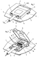
- the mains connection box 1 shown in FIGS. 1 to 5 has a housing 2 with a lid 3, which are made of plastic.
- the Mains connection box 1 is in a device wall recess 7 of a device wall 6 arranged of a household appliance.
- the plastic housing 2 of the Mains connection box 1 in this case latches 10, which in the assembled state the power socket 1, the wall of the appliance 6 through the Reach behind the device wall recess 7 and so the housing 2 Attach the mains socket 1 to the appliance wall 6 of the household appliance, such as can be seen in particular from FIG. 3.
- the cover 3 of the mains connection box 1 can be pivoted on the housing 2 attached.
- the cover has 3 bearing pins 11, which have bearing mounts 12 on the part of the housing 2 correspond, as in particular with reference to FIG 4 recognizable.
- this has a recess for carrying out the Power cord 8 on.
- a corresponding recess is on the part of the Housing 2 between the locking lugs 13 for locking the cover 3rd provided, as can be seen in Figure 4.
- the power cord 8 has a plurality of lines 9, which with as Insulation displacement contacts trained input contacts 4 are connected.
- the Input contacts 4 designed as insulation displacement contacts are included in the present case in a chamber-like housing serving as a plug 18 arranged, which is substantially perpendicular to the direction of extension of the power cord 8 extends.
- the chamber-like housing 18 with input contacts 4 designed as insulation displacement contacts, which in a predeterminable grid can be arranged in the chambers of the housing 18 in the context of automated or partially automated production stockable and mountable. So power cord 8 and housing 18 with Input contacts 4 sorted and stocked in rod magazines successively assembled for pre-assembly. Beyond that a correspondingly provided with housing 18 with input contacts 4 Power cord 8 as an intermediate in the manufacture of a Mains socket 1 automated and / or fully automated with the Mains socket 1 connectable.
- the housing 2 of the mains connection box 1 further points inside the housing 2 one with the plug-like housing 18 of the input contacts 4 cooperating receptacle 16, in which the housing 18 of the Input contacts 4 can be inserted by clamping.
- the recording 16 are Sections 20 of the output contacts 5 for connection to the input contacts 4 arranged, as can be seen in particular from FIGS. 4 and 5.
- the Input contacts 4 are thereby simply plugged onto sections 20 the output contacts 5 can be electrically connected to them, such that the Output contacts 5 at least partially via the input contacts 4 on the part of the power cord 8 supplied electrical energy can be supplied.
- the output contacts 5 on the part of the housing 2 also have sections 21, which in the plug-in direction of the housing 2 of the power socket 1 for Household appliance extend beyond the housing 2 and out of this protrude.
- the sections 21 of the output contacts 5 act thereby to supply the household appliance with energy, similar explicitly shown counter contacts together.
- the Sections 21 of the output contacts 5 serve the chamber-like Housing projections 15 in addition to guiding the mating connector of the Household appliances during the contacting process.
- the mains socket 1 has an earthing lug 19, which laterally from the Housing 2 of the power socket 1 protrudes and on the wall 6 of the Household appliance rests or can be attached to it by means of screws.
Landscapes
- Details Of Connecting Devices For Male And Female Coupling (AREA)
- Connector Housings Or Holding Contact Members (AREA)
Applications Claiming Priority (2)
| Application Number | Priority Date | Filing Date | Title |
|---|---|---|---|
| DE20204069U | 2002-03-14 | ||
| DE20204069U DE20204069U1 (de) | 2002-03-14 | 2002-03-14 | Netzanschlußdose für elektrisch betreibbare Geräte |
Publications (2)
| Publication Number | Publication Date |
|---|---|
| EP1345285A2 true EP1345285A2 (fr) | 2003-09-17 |
| EP1345285A3 EP1345285A3 (fr) | 2005-12-07 |
Family
ID=7968941
Family Applications (1)
| Application Number | Title | Priority Date | Filing Date |
|---|---|---|---|
| EP03005679A Withdrawn EP1345285A3 (fr) | 2002-03-14 | 2003-03-13 | Boítier de raccordement pour appareillages à commande électrique |
Country Status (2)
| Country | Link |
|---|---|
| EP (1) | EP1345285A3 (fr) |
| DE (1) | DE20204069U1 (fr) |
Cited By (3)
| Publication number | Priority date | Publication date | Assignee | Title |
|---|---|---|---|---|
| WO2012155164A3 (fr) * | 2011-05-13 | 2013-01-10 | Tridonic Connection Technology Gmbh & Co Kg | Dispositif de raccordement pour la liaison électrique d'un câble, et appareil électrique |
| WO2024156584A1 (fr) * | 2023-01-24 | 2024-08-02 | Electro Terminal Gmbh & Co Kg | Boîte de jonction de câble comprenant une connexion par serrage à ressort |
| EP4726938A1 (fr) * | 2024-10-09 | 2026-04-15 | Electro Terminal GmbH & Co KG | Boîte de connexion de câble et appareil électrique l'utilisant |
Families Citing this family (2)
| Publication number | Priority date | Publication date | Assignee | Title |
|---|---|---|---|---|
| DE20303488U1 (de) | 2003-03-05 | 2003-06-26 | STOCKO Contact GmbH & Co. KG, 42327 Wuppertal | Netzanschlußdose für elektrisch betreibbare Geräte |
| ITVA20100002U1 (it) * | 2010-01-15 | 2011-07-16 | Gvp Elettronica Srl | Modulo di ingresso rete (in differenti configurazioni, da 90 a 250 vac, 10 a sino a max 16 a, con frequanza da 50 sino a 60 hz) completo di filtro emc e grado minimo di protezione ipx4 con cavo di rete separabile tramite l'uso di utensile, per grandi |
Family Cites Families (5)
| Publication number | Priority date | Publication date | Assignee | Title |
|---|---|---|---|---|
| US4050764A (en) * | 1976-01-14 | 1977-09-27 | Amp Incorporated | Intrinsic certification assembly technique for wiring components into an electrical apparatus |
| DE4331212C2 (de) * | 1993-09-10 | 1997-04-30 | Krone Ag | Klemmanschlußeinheit |
| US5626490A (en) | 1995-09-25 | 1997-05-06 | The Whitaker Corporation | Wire stuffer cap/strain relief for communication network outlet |
| DE19540329A1 (de) | 1995-10-28 | 1997-04-30 | Merten Gmbh & Co Kg Geb | Elektrische Anschlußvorrichtung für mobile Geräte |
| DE19949386C2 (de) | 1999-10-13 | 2002-04-11 | Electro Terminal Gmbh | Geräte-Anschlusskasten mit Schneidtechnik |
-
2002
- 2002-03-14 DE DE20204069U patent/DE20204069U1/de not_active Expired - Lifetime
-
2003
- 2003-03-13 EP EP03005679A patent/EP1345285A3/fr not_active Withdrawn
Cited By (3)
| Publication number | Priority date | Publication date | Assignee | Title |
|---|---|---|---|---|
| WO2012155164A3 (fr) * | 2011-05-13 | 2013-01-10 | Tridonic Connection Technology Gmbh & Co Kg | Dispositif de raccordement pour la liaison électrique d'un câble, et appareil électrique |
| WO2024156584A1 (fr) * | 2023-01-24 | 2024-08-02 | Electro Terminal Gmbh & Co Kg | Boîte de jonction de câble comprenant une connexion par serrage à ressort |
| EP4726938A1 (fr) * | 2024-10-09 | 2026-04-15 | Electro Terminal GmbH & Co KG | Boîte de connexion de câble et appareil électrique l'utilisant |
Also Published As
| Publication number | Publication date |
|---|---|
| EP1345285A3 (fr) | 2005-12-07 |
| DE20204069U1 (de) | 2002-05-23 |
Similar Documents
| Publication | Publication Date | Title |
|---|---|---|
| DE202017101060U1 (de) | Steckverbinder, insbesondere für eine Hochstromanwendung | |
| DE112010000444T5 (de) | Masseverbindungsstecker und Kabelbaum hiermit | |
| WO2020187356A1 (fr) | Support de contact et connecteur pour un agencement de contacts hybride blindé | |
| EP1088374B1 (fr) | Adaptateur de traversee pour armoire electrique | |
| DE102011112283B4 (de) | Modulares elektrisches Steckverbindersystem für Solaranlagen | |
| DE29521213U1 (de) | Steckverbindersystem | |
| EP2672574B1 (fr) | Connecteur plat pratique | |
| EP1345285A2 (fr) | Boítier de raccordement pour appareillages à commande électrique | |
| EP2107649B1 (fr) | Connecteur configurable pour moteur électrique | |
| DE202015008215U1 (de) | Kontaktierungsvorrichtung, Anschlussgehäuse, Stellantrieb und Baureihe | |
| EP3480895A1 (fr) | Unité de raccordement d'appareils pour un appareil électrique et appareil électrique | |
| DE4239261A1 (de) | Steckerbrücke für einen elektrischen Gerätestecker mit einem Paar von Stromleiterstiften (Kontaktstiften) und gegebenenfalls einem Schutzleiterstift (Erdstiift) | |
| DE102022122248B4 (de) | Anschlussklemme | |
| EP3369933A1 (fr) | Pompe de circulation de chauffage | |
| EP0452688A1 (fr) | Pièce de connexion pour une connexion à fiche électrique et optico-conductive | |
| EP4150718A1 (fr) | Corps isolant de contacts à vis et à sertir | |
| DE4437338A1 (de) | Kabel-Steckverbindung für den druckfest gekapselten Elektromotor einer Tauchmotorpumpe | |
| DE20303488U1 (de) | Netzanschlußdose für elektrisch betreibbare Geräte | |
| KR102788375B1 (ko) | 배터리 관리 시스템용 대전류 플러그인 커넥터 | |
| EP0973281A1 (fr) | Filtre de ligne et boitier de connexion avec un filtre de ligne | |
| EP0697751A1 (fr) | Boîte de dérivation | |
| DE2124790A1 (de) | Elektrische Leitungsverbindung zwischen dem Anschlußkabel und den Strom1 Zuführungsleitungen einer Kabelaufwickelvorrichtung, insbesondere für Staubsauger | |
| EP0690544A2 (fr) | Connexion de câble enfichable pour moteur électrique en capsule résistante à la pression d'une motopompe submersible | |
| DE2924906A1 (de) | Elektrischer anschluss zwischen motoren- wicklung(en) und anschlussleitung(en) | |
| EP3561961B1 (fr) | Raccordement moteur pour un moteur électrique |
Legal Events
| Date | Code | Title | Description |
|---|---|---|---|
| PUAI | Public reference made under article 153(3) epc to a published international application that has entered the european phase |
Free format text: ORIGINAL CODE: 0009012 |
|
| AK | Designated contracting states |
Kind code of ref document: A2 Designated state(s): AT BE BG CH CY CZ DE DK EE ES FI FR GB GR HU IE IT LI LU MC NL PT SE SI SK TR |
|
| AX | Request for extension of the european patent |
Extension state: AL LT LV MK RO |
|
| PUAL | Search report despatched |
Free format text: ORIGINAL CODE: 0009013 |
|
| AK | Designated contracting states |
Kind code of ref document: A3 Designated state(s): AT BE BG CH CY CZ DE DK EE ES FI FR GB GR HU IE IT LI LU MC NL PT SE SI SK TR |
|
| AX | Request for extension of the european patent |
Extension state: AL LT LV MK RO |
|
| 17P | Request for examination filed |
Effective date: 20060330 |
|
| AKX | Designation fees paid |
Designated state(s): BE DE FR GB IT |
|
| STAA | Information on the status of an ep patent application or granted ep patent |
Free format text: STATUS: THE APPLICATION IS DEEMED TO BE WITHDRAWN |
|
| 18D | Application deemed to be withdrawn |
Effective date: 20071002 |