EP1345475A2 - Gerät und Verfahren zur Versorgungssteuerung einer elektrischen Last - Google Patents
Gerät und Verfahren zur Versorgungssteuerung einer elektrischen Last Download PDFInfo
- Publication number
- EP1345475A2 EP1345475A2 EP03251476A EP03251476A EP1345475A2 EP 1345475 A2 EP1345475 A2 EP 1345475A2 EP 03251476 A EP03251476 A EP 03251476A EP 03251476 A EP03251476 A EP 03251476A EP 1345475 A2 EP1345475 A2 EP 1345475A2
- Authority
- EP
- European Patent Office
- Prior art keywords
- load
- drive
- state
- electrical loads
- electrical
- Prior art date
- Legal status (The legal status is an assumption and is not a legal conclusion. Google has not performed a legal analysis and makes no representation as to the accuracy of the status listed.)
- Granted
Links
Images


Classifications
-
- H—ELECTRICITY
- H05—ELECTRIC TECHNIQUES NOT OTHERWISE PROVIDED FOR
- H05B—ELECTRIC HEATING; ELECTRIC LIGHT SOURCES NOT OTHERWISE PROVIDED FOR; CIRCUIT ARRANGEMENTS FOR ELECTRIC LIGHT SOURCES, IN GENERAL
- H05B39/00—Circuit arrangements or apparatus for operating incandescent light sources
- H05B39/04—Controlling
-
- H—ELECTRICITY
- H05—ELECTRIC TECHNIQUES NOT OTHERWISE PROVIDED FOR
- H05B—ELECTRIC HEATING; ELECTRIC LIGHT SOURCES NOT OTHERWISE PROVIDED FOR; CIRCUIT ARRANGEMENTS FOR ELECTRIC LIGHT SOURCES, IN GENERAL
- H05B47/00—Circuit arrangements for operating light sources in general, i.e. where the type of light source is not relevant
- H05B47/20—Responsive to malfunctions or to light source life; for protection
Definitions
- the present invention relates to an apparatus and a method adopted to implement drive control of electrical loads. More specifically, it relates to an apparatus and a method adopted to implement drive control of electrical loads in a vehicle.
- an electrical load control apparatus employed to control electrical loads in a vehicle in the related art that drives a headlamp comprising a main (hereafter referred to as a "high beam”) lamp and a dimmer (hereafter referred to as a "low beam”) lamp by lighting high beam lamp with a high beam FET and lighting the low beam lamp with a low beam FET (see Japanese Laid Open Patent Publication No. 2001-187545). It is to be noted that some control apparatuses utilize relays instead of FETs in the lamp drive circuits.
- An electrical load drive control apparatus comprises : a plurality of drive units, each of which drives one of a plurality of electrical loads; an instruction unit that issues a drive switch instruction to switch drive among the plurality of electrical loads; a detection unit that detects a non-operating state of the plurality of electrical loads; and a control unit that controls the plurality of drive units based upon the drive switch instruction issued by the instruction unit and results of a detection by the detection unit.
- control unit controls the plurality of drive units so as to set all of the plurality of electrical loads in a non-operating state if an instruction to switch drive among the plurality of electrical loads is issued by the instruction unit, and controls the plurality of drive units so as to switch drive to an electrical load selected through the drive switch instruction after verifying that the plurality of electrical loads are all set in a non-operating state based upon the results of the detection by the detection unit.
- An electrical load drive control method comprises: setting all of a plurality of electrical loads into a non-operating state if a drive switch instruction to switch drive among the plurality of electrical loads is issued; verifying whether or not all of the plurality of electrical loads have entered a non-operating state; and switching to drive an electrical load selected through the drive switch instruction after verifying that all of the plurality of electrical loads have been set in a non-operating state.
- FIG. 1 shows the structure adopted in the embodiment.
- a headlamp 1 and a headlamp 2 respectively on the left side and the right side viewed from the front of the vehicle each include a high beam filament 1a or 2a and a low beam filament 1b or 2b provided within a single bulb.
- a high beam relay 3 applies power from a battery 4 to the high beam filaments 1a and 2a via fuses 5a and 5b to turn on the left and right headlamps 1 and 2 to high beams.
- a low beam relay 6 applies power from the battery 4 to the low beam filaments 1b and 2b via fuses 7a and 7b to turn on the left and right headlamps 1 and 2 to low beams.
- a light switch 8 is operated to select a high beams ON state (8a), a low beams ON state (8b), or a headlamps OFF state (8c).
- the light switch 8 is set to the high beams ON position 8a, the power from the battery 4 is applied to a high beam setting detection circuit 10 via a CR input circuit 9 (R1, R2, and C1), and the high beam setting detection circuit 10, in turn, outputs a high level signal "1" to an input terminal 1H of a microcomputer 11.
- the light switch 8 When the light switch 8 is set to the low beams ON position 8b, the power from the battery 4 is applied to a low beam setting detection circuit 13 via a CR input circuit 12 (R3, R4,and C2), and the low beam setting detection circuit 13 outputs a high-level signal "1" to an input terminal IL of the microcomputer 11.
- a CR input circuit 12 R3, R4,and C2
- the microcomputer 11 which includes peripheral components such as ROM and RAM, executes a control program to be detailed later to implement ON/OFF control for low beams and high beams at the left and right headlamps 1 and 2.
- a high beam relay drive circuit 14 (R5, R6, and Tr1) drives a coil 3a of the high beam relay 3.
- the transistor Tr1 of the high beam relay drive circuit 14 becomes electrically turned on to allow the power from the battery 4 to be supplied to the relay coil 3a thereby turning on the high beam relay 3.
- a low beam relay drive circuit 15 (R7, R8, and Tr2) drives a coil 6a of the low beam relay 6.
- the transistor Tr2 of the low beam relay drive circuit 15 becomes electrically turned on to allow the power from the battery 4 to be supplied to the relay coil 6a, thereby turning on the low beam relay 6.
- the high beam relay 3 When the high beam relay 3 is in an ON state and thus high beams at the left and right headlamps 1 and 2 are on, the voltage at the battery 4 is applied to a high beam monitor circuit 17 via the relay 3 and a CR input circuit (R11, R12, and C4), and the high beam monitor circuit 17 outputs a high-level signal "1" to a monitor terminal MH of the microcomputer 11.
- the voltage of the battery 4 is applied to a low beam monitor circuit 19 via the relay 6 and a CR input circuits 18 (R9, R10,and C3), and, as a result, the monitor circuit 19 outputs a high-level signal "1" to monitor terminal ML of the microcomputer 11.
- An output circuit 20 drives a display 21 and a speaker 22 to provide a warning in the form of a text message and a voice message when a fusion failure has occurred at the contact point of the high beam relay 3 or the low beam relay 6 or when an ON failure has occurred at the transistor Tr1 of the high beam relay drive circuit 14 or the transistor Tr2 of the low beam relay drive circuit 15.
- FIG. 2 presents a flowchart of the headlamp ON/OFF control program and FIG. 3 is a transition diagram of the ON/OFF states of the low beams and the high beams.
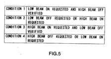
- FIG. 5 presents Table 1 of the transition conditions for the ON/OFF states of the low beam and the high beams.
- the microcomputer 11 executes the headlamp ON/OFF control program shown in FIG. 2 over predetermined time intervals (e.g., approximately every 10msec).
- step S1 the signal levels at the input terminals IH and IL are read to check the setting status of the light switch 8.
- the signal levels at the monitor terminals MH and ML are read to check the ON/OFF states of the low beams and the high beams.
- step S3 a verification is made to determine whether or not any of conditions 1 ⁇ 4 in Table 1 of FIG. 5 is achieved, based upon the setting status of the light switch 8 and the ON/OFF states of the low beams and the high beams. If one of the conditions 1 ⁇ 4 is achieved, the operation proceeds to step S4 to induce a transition in conformance to the transition condition shown in FIG.3 to implement ON/OFF control on the low beams and the high beams.
- the output levels of the high beam setting detection circuit 10 and the low beam setting detection circuit 13, i.e., the levels at the input terminals IH and IL of the microcomputer 11, are both "0" and the low beams and the high beams are both off, as in "the state 1" in FIG. 3.
- step S1 the microcomputer 11 reads the setting status of the light switch 8 to indicate that a low beam ON request has been issued.
- step S2 the ON/OFF states of the low beams and the high beams are verified in step S2. At this point, both the low beams and the high beams are in an OFF state.
- step S3 When a low beam ON request has been issued and, at the same time, the high beams are determined to be in an OFF state, it is decided in step S3 that the condition 1 in Table 1 is satisfied and then the operation proceeds to step S4.
- step S4 a transition from the state 1 to the state 2 is made in conformance to the condition 1 to turn on the low beams while the high beams remain off.
- step S1 the microcomputer 11 determines the setting status of the light switch 8 to indicate that a low beam OFF request and a high beam ON request have been issued.
- step S2 the ON/OFF states of the low beams and the high beams are checked. At this point, the low beams are on.
- step S3 When there is a high beam ON request while the low beams are on, i.e., in the transition state 2, it is decided in step S3 that the condition 2 in Table 1 is achieved and the operation then proceeds to step S4.
- step S4 a transition from the state 2 to the state 1 is made in conformance to the condition 2 to turn off both the low beams and the high beams.
- the ON/OFF control program in FIG. 2 is executed again after the predetermined time interval to check whether or not a high beam ON request is currently issued in step S1. Then, in the following step S2, the ON/OFF states of the low beams and the high beams are checked. At this point, both the low beams and the high beams are off.
- step S3 When there is a high beam ON request and, at the same time, it is verified that the low beams are off in the transition state 1, it is decided in step S3 that the transition condition 3 in Table 1 is achieved and then the operation proceeds to step S4 .
- step S4 a transition from the state 1 to the state 3 is made in conformance to the condition 3 to turn on the high beams while the low beams remain off.
- step S1 the microcomputer 11 determines the setting status of the light switch 8 to indicate that a high beam OFF request and a low beam ON request have been issued.
- step S2 the ON/OFF states of the low beams and the high beams are checked. At this point, the high beams are off.
- step S3 When there is a low beam ON request in the transition state 3, i.e., while the high beams are on, it is decided in step S3 that the condition 4 in Table 1 is achieved before the operation proceeds to step S4.
- step S4 a transition from the state 3 to the state 1 is made in conformance to the condition 4 to turn off both the low beams and the high beams.
- the ON/OFF control program in FIG. 2 is executed again after the predetermined time interval to check whether or not a low beam ON request is currently issued in step S1. Then, in the following step S2, the ON/OFF states of the low beams and the high beams are checked. At this point, both the low beams and the high beams are off.
- step S3 When there is a low beam ON request and, at the same time, it is verified that the high beams are off in the transition state 1, it is decided in step S3 that the transition condition 1 in Table 1 is achieved and then the operation proceeds to step S4 .
- step S4 a transition from the state 1 to the state 2 is made in conformance to the condition 1 to turn on the low beams while the high beams remain off.
- step S1 the microcomputer 11 determines the setting status of the light switch 8 to indicate that a low beam OFF request has been issued.
- step S3 When there is a low beam OFF request in the transition state 1, it is decided in step S3 that the transition condition 2 in Table 1 is achieved before the operation proceeds to step S4. In step S4, a transition from the state 2 to the state 1 is made in conformance to the condition 2 to turn off low beams.
- the high beam ON request is continuously issued as long as the setting at the light switch 8 remains unchanged.
- the low beams are still on due to the contact fusion at the low beam relay 6 or the ON failure of the transistor Tr2 of the low beam relay drive circuit 15, the level at the monitor terminal ML remains high.
- the transition condition 3 in Table 1 is not achieved. Accordingly, the state 1 is sustained without making a transition to the state 3.
- the low beam ON request is continuously issued as long as the setting status of the light switch 8 remains unchanged.
- the high beams are still on due to the contact fusion at the high beam relay 3 or due to the ON failure of the transistor Tr1 of the high beam relay drive circuit 14, the level at the monitor terminal MH remains high.
- the transition condition 1 in Table 1 is not achieved. Accordingly the state 1 is sustained without making a transition to the state 2.
- the transition from the state 2 to the state 3 or from the state 3 to the state 2 is invariably made by first shifting into the state 1 to verify that the low beams and the high beams are both off and, as a result, the low beams and the high beams are not allowed to be turned on at the same time even if a fusion failure has occurred at the contact point at the low beam relay 6 or the high beam relay 3 or an ON failure has occurred at the transistor Tr2 of the low beam relay drive circuit 15 or the transistor Tr1 of the high beam relay drive circuit 14.
- FIG. 4 shows an example of a variation of the embodiment. It is to be noted that the same reference numerals are assigned to components identical to those in FIG. 1 and the following explanation focuses on the difference.
- an OR circuit 30, a CR input circuit (R13, R14, and C5) 31 and a monitor circuit 32 are employed in place of the CR input circuit 16 and the monitor circuit 17 for the low beams and the CR input circuit 18 and the monitor circuit 19 for high beams shown in FIG. 1.
- the output voltage of the OR circuit 30 is equal to the terminal voltage at the battery 4 .
- the monitor circuit 32 outputs a signal indicating that a high level "1" to a monitor terminal M of the microcomputer 11. If, on the other hand, both the low beams and the high beams are off, the output voltage of the OR circuit 30 is 0V. In this case, the monitor circuit 32 outputs a low level "0" to the monitor terminal M.
- the level at the monitor terminal M is low, i.e., "0", in the transition state 1, it can be judged that both the low beams and the high beams are off.
- a simpler circuit structure is achieved in the variation compared to that of the monitor circuits in the embodiment described earlier and, as a result, the number of input terminals at the microcomputer 11 can be reduced.
- the present invention may be adopted in conjunction with vehicle electrical loads other than headlamps.
- the electrical loads may be the left and right turn signal lamps instead.
- the present invention may be adopted in conjunction with any electrical loads that are alternately engaged in operation.
- the number of electrical loads is not limited to the example of the embodiment.
- the present invention may be adopted in conjunction with electrical loads in non-automotive applications.
- the terms "electrical loads” as referred to in this context may be regarded to mean electrical or electronic components, electrical or electronic elements,or electrical or electronic devices.
- the present invention is not limited to this example.
- the electrical loads may instead be driven by implementing control so as to lower the potential at either terminal to the ground level while applying the voltage to another terminal.
- the present invention may be adopted in any method for driving electrical loads in a vehicle.
Landscapes
- Lighting Device Outwards From Vehicle And Optical Signal (AREA)
- Direct Current Feeding And Distribution (AREA)
Applications Claiming Priority (2)
| Application Number | Priority Date | Filing Date | Title |
|---|---|---|---|
| JP2002066582 | 2002-03-12 | ||
| JP2002066582A JP4069647B2 (ja) | 2002-03-12 | 2002-03-12 | 車両用電装負荷制御装置 |
Publications (3)
| Publication Number | Publication Date |
|---|---|
| EP1345475A2 true EP1345475A2 (de) | 2003-09-17 |
| EP1345475A3 EP1345475A3 (de) | 2003-11-19 |
| EP1345475B1 EP1345475B1 (de) | 2006-12-13 |
Family
ID=27764487
Family Applications (1)
| Application Number | Title | Priority Date | Filing Date |
|---|---|---|---|
| EP03251476A Expired - Lifetime EP1345475B1 (de) | 2002-03-12 | 2003-03-10 | Gerät und Verfahren zur Versorgungssteuerung einer elektrischen Last |
Country Status (4)
| Country | Link |
|---|---|
| US (1) | US6958897B2 (de) |
| EP (1) | EP1345475B1 (de) |
| JP (1) | JP4069647B2 (de) |
| DE (1) | DE60310285T2 (de) |
Families Citing this family (5)
| Publication number | Priority date | Publication date | Assignee | Title |
|---|---|---|---|---|
| DE102005006288A1 (de) * | 2005-02-11 | 2006-09-07 | Bayerische Motoren Werke Ag | Verfahren zur Betätigung von Schweinwerfern eines Kraftfahrzeugs |
| JP4561715B2 (ja) * | 2006-09-21 | 2010-10-13 | 住友電装株式会社 | ヘッドランプ制御回路 |
| JP4730791B2 (ja) * | 2007-04-18 | 2011-07-20 | 株式会社小糸製作所 | 車両用前照灯装置 |
| JP4989538B2 (ja) * | 2008-03-27 | 2012-08-01 | 本田技研工業株式会社 | 車両用制御装置、電気車両及び車両用制御装置の故障検出方法 |
| JP4989537B2 (ja) * | 2008-03-27 | 2012-08-01 | 本田技研工業株式会社 | 車両用制御装置、電気車両及び車両用制御装置の故障検出方法 |
Family Cites Families (7)
| Publication number | Priority date | Publication date | Assignee | Title |
|---|---|---|---|---|
| US3876904A (en) | 1974-01-28 | 1975-04-08 | Rockwell International Corp | Light switch control |
| US4236084A (en) * | 1978-10-26 | 1980-11-25 | Gingras Richard P | Apparatus and method for in-line energization and de-energization of external loads in series with an external source of electricity in response to externally sensed parameters |
| JP2874313B2 (ja) | 1990-09-21 | 1999-03-24 | 日産自動車株式会社 | 車両用前照灯の制御装置 |
| JPH07228186A (ja) | 1994-02-18 | 1995-08-29 | Anden Kk | ヘッドライト制御装置 |
| JPH08282367A (ja) | 1995-04-18 | 1996-10-29 | Anden Kk | ヘッドライト制御装置 |
| US6127741A (en) * | 1997-03-17 | 2000-10-03 | The Furukawa Electric Co., Ltd. | Vehicular use power feed apparatus |
| JP2001187545A (ja) | 1999-12-28 | 2001-07-10 | Taiheiyo Seiko Kk | 負荷駆動制御装置 |
-
2002
- 2002-03-12 JP JP2002066582A patent/JP4069647B2/ja not_active Expired - Lifetime
-
2003
- 2003-03-06 US US10/379,663 patent/US6958897B2/en not_active Expired - Lifetime
- 2003-03-10 EP EP03251476A patent/EP1345475B1/de not_active Expired - Lifetime
- 2003-03-10 DE DE60310285T patent/DE60310285T2/de not_active Expired - Lifetime
Also Published As
| Publication number | Publication date |
|---|---|
| DE60310285T2 (de) | 2007-07-05 |
| US20030174448A1 (en) | 2003-09-18 |
| JP4069647B2 (ja) | 2008-04-02 |
| US6958897B2 (en) | 2005-10-25 |
| EP1345475A3 (de) | 2003-11-19 |
| DE60310285D1 (de) | 2007-01-25 |
| JP2003260977A (ja) | 2003-09-16 |
| EP1345475B1 (de) | 2006-12-13 |
Similar Documents
| Publication | Publication Date | Title |
|---|---|---|
| US6417624B1 (en) | Lighting system for vehicle | |
| US7659670B2 (en) | Headlamp control circuit | |
| US7075237B2 (en) | Illumination control apparatus and failure detecting apparatus | |
| EP1345475B1 (de) | Gerät und Verfahren zur Versorgungssteuerung einer elektrischen Last | |
| JPH1086746A (ja) | 自動車用ヘッドランプ制御回路 | |
| EP1140559A1 (de) | Scheinwerfereinrichtung für kraftfahrzeuge | |
| EP1328053A2 (de) | Stromversorgungssystem | |
| JP2003054309A (ja) | 車両用灯具装置 | |
| JPH0332493B2 (de) | ||
| JP2002144958A (ja) | 車両用ランプの点灯制御装置 | |
| KR20060107059A (ko) | 가스 방전램프를 구비한 차량용 전조등 | |
| JP4687173B2 (ja) | 放電灯点灯装置および車両用灯具 | |
| EP1500556B1 (de) | Fahrzeug-Scheinwerfer-System | |
| JP4678355B2 (ja) | ヘッドランプ制御回路 | |
| KR100391725B1 (ko) | 차량용 헤드 램프 장치 | |
| JPH0237638Y2 (de) | ||
| KR100401772B1 (ko) | 주간 운행등이 적용된 자동차용 고광도 헤드 램프 제어 회로 | |
| JP2006298038A (ja) | 負荷電力供給ユニット及び車両用ランプ制御装置 | |
| JPH10250476A (ja) | ランプ類の断線検出装置 | |
| KR100187419B1 (ko) | 2중 필라멘트부를 갖는 차량램프용 전구의 수명연장회로 | |
| JPH027722Y2 (de) | ||
| JP2009277440A (ja) | ランプ駆動装置 | |
| KR19990010567U (ko) | 자동차 전조등의 점소등 제어장치 | |
| KR19980086104A (ko) | 차량용 후미등 제어장치 | |
| JPS58167233A (ja) | 車両用自動点灯装置 |
Legal Events
| Date | Code | Title | Description |
|---|---|---|---|
| PUAI | Public reference made under article 153(3) epc to a published international application that has entered the european phase |
Free format text: ORIGINAL CODE: 0009012 |
|
| 17P | Request for examination filed |
Effective date: 20030404 |
|
| AK | Designated contracting states |
Kind code of ref document: A2 Designated state(s): AT BE BG CH CY CZ DE DK EE ES FI FR GB GR HU IE IT LI LU MC NL PT RO SE SI SK TR |
|
| AX | Request for extension of the european patent |
Extension state: AL LT LV MK RO |
|
| PUAL | Search report despatched |
Free format text: ORIGINAL CODE: 0009013 |
|
| AK | Designated contracting states |
Kind code of ref document: A3 Designated state(s): AT BE BG CH CY CZ DE DK EE ES FI FR GB GR HU IE IT LI LU MC NL PT RO SE SI SK TR |
|
| AX | Request for extension of the european patent |
Extension state: AL LT LV MK RO |
|
| AKX | Designation fees paid |
Designated state(s): DE FR GB |
|
| GRAP | Despatch of communication of intention to grant a patent |
Free format text: ORIGINAL CODE: EPIDOSNIGR1 |
|
| GRAS | Grant fee paid |
Free format text: ORIGINAL CODE: EPIDOSNIGR3 |
|
| GRAA | (expected) grant |
Free format text: ORIGINAL CODE: 0009210 |
|
| AK | Designated contracting states |
Kind code of ref document: B1 Designated state(s): DE FR GB |
|
| REG | Reference to a national code |
Ref country code: GB Ref legal event code: FG4D |
|
| REF | Corresponds to: |
Ref document number: 60310285 Country of ref document: DE Date of ref document: 20070125 Kind code of ref document: P |
|
| ET | Fr: translation filed | ||
| PLBE | No opposition filed within time limit |
Free format text: ORIGINAL CODE: 0009261 |
|
| STAA | Information on the status of an ep patent application or granted ep patent |
Free format text: STATUS: NO OPPOSITION FILED WITHIN TIME LIMIT |
|
| 26N | No opposition filed |
Effective date: 20070914 |
|
| REG | Reference to a national code |
Ref country code: FR Ref legal event code: PLFP Year of fee payment: 14 |
|
| REG | Reference to a national code |
Ref country code: FR Ref legal event code: PLFP Year of fee payment: 15 |
|
| REG | Reference to a national code |
Ref country code: FR Ref legal event code: PLFP Year of fee payment: 16 |
|
| REG | Reference to a national code |
Ref country code: DE Ref legal event code: R079 Ref document number: 60310285 Country of ref document: DE Free format text: PREVIOUS MAIN CLASS: H05B0033080000 Ipc: H05B0045000000 |
|
| PGFP | Annual fee paid to national office [announced via postgrant information from national office to epo] |
Ref country code: GB Payment date: 20220120 Year of fee payment: 20 Ref country code: DE Payment date: 20220112 Year of fee payment: 20 |
|
| PGFP | Annual fee paid to national office [announced via postgrant information from national office to epo] |
Ref country code: FR Payment date: 20220118 Year of fee payment: 20 |
|
| REG | Reference to a national code |
Ref country code: DE Ref legal event code: R071 Ref document number: 60310285 Country of ref document: DE |
|
| REG | Reference to a national code |
Ref country code: GB Ref legal event code: PE20 Expiry date: 20230309 |
|
| PG25 | Lapsed in a contracting state [announced via postgrant information from national office to epo] |
Ref country code: GB Free format text: LAPSE BECAUSE OF EXPIRATION OF PROTECTION Effective date: 20230309 |