EP1345512B1 - Aus kugeln bestehendes gefüge als polsterelement eines sitzmöbels, und verfahren zu dessen herstellung - Google Patents
Aus kugeln bestehendes gefüge als polsterelement eines sitzmöbels, und verfahren zu dessen herstellung Download PDFInfo
- Publication number
- EP1345512B1 EP1345512B1 EP01949805A EP01949805A EP1345512B1 EP 1345512 B1 EP1345512 B1 EP 1345512B1 EP 01949805 A EP01949805 A EP 01949805A EP 01949805 A EP01949805 A EP 01949805A EP 1345512 B1 EP1345512 B1 EP 1345512B1
- Authority
- EP
- European Patent Office
- Prior art keywords
- balls
- inox
- frame
- wire cable
- column
- Prior art date
- Legal status (The legal status is an assumption and is not a legal conclusion. Google has not performed a legal analysis and makes no representation as to the accuracy of the status listed.)
- Expired - Lifetime
Links
- 238000000034 method Methods 0.000 title claims description 16
- 239000000463 material Substances 0.000 claims abstract description 8
- 239000011796 hollow space material Substances 0.000 claims 1
- 239000002184 metal Substances 0.000 claims 1
- 239000011343 solid material Substances 0.000 claims 1
- 239000002023 wood Substances 0.000 claims 1
- 239000006096 absorbing agent Substances 0.000 abstract description 2
- 238000010276 construction Methods 0.000 description 5
- 238000009434 installation Methods 0.000 description 4
- 238000004519 manufacturing process Methods 0.000 description 3
- 229910000831 Steel Inorganic materials 0.000 description 1
- 230000006978 adaptation Effects 0.000 description 1
- 230000002730 additional effect Effects 0.000 description 1
- 230000003466 anti-cipated effect Effects 0.000 description 1
- 230000005540 biological transmission Effects 0.000 description 1
- 230000007797 corrosion Effects 0.000 description 1
- 238000005260 corrosion Methods 0.000 description 1
- 230000000694 effects Effects 0.000 description 1
- 238000005516 engineering process Methods 0.000 description 1
- 238000009776 industrial production Methods 0.000 description 1
- 239000011159 matrix material Substances 0.000 description 1
- 239000000203 mixture Substances 0.000 description 1
- 239000011253 protective coating Substances 0.000 description 1
- 230000000284 resting effect Effects 0.000 description 1
- 230000035939 shock Effects 0.000 description 1
- 230000003068 static effect Effects 0.000 description 1
- 239000010959 steel Substances 0.000 description 1
- 230000003319 supportive effect Effects 0.000 description 1
Images

Classifications
-
- A—HUMAN NECESSITIES
- A47—FURNITURE; DOMESTIC ARTICLES OR APPLIANCES; COFFEE MILLS; SPICE MILLS; SUCTION CLEANERS IN GENERAL
- A47C—CHAIRS; SOFAS; BEDS
- A47C7/00—Parts, details, or accessories of chairs or stools
- A47C7/02—Seat parts
- A47C7/024—Seat parts with double seats
-
- A—HUMAN NECESSITIES
- A47—FURNITURE; DOMESTIC ARTICLES OR APPLIANCES; COFFEE MILLS; SPICE MILLS; SUCTION CLEANERS IN GENERAL
- A47C—CHAIRS; SOFAS; BEDS
- A47C7/00—Parts, details, or accessories of chairs or stools
- A47C7/02—Seat parts
- A47C7/14—Seat parts of adjustable shape; elastically mounted ; adaptable to a user contour or ergonomic seating positions
- A47C7/144—Seat parts of adjustable shape; elastically mounted ; adaptable to a user contour or ergonomic seating positions with array of movable supports
-
- A—HUMAN NECESSITIES
- A47—FURNITURE; DOMESTIC ARTICLES OR APPLIANCES; COFFEE MILLS; SPICE MILLS; SUCTION CLEANERS IN GENERAL
- A47C—CHAIRS; SOFAS; BEDS
- A47C7/00—Parts, details, or accessories of chairs or stools
- A47C7/36—Supports for the head or the back
- A47C7/40—Supports for the head or the back for the back
- A47C7/405—Supports for the head or the back for the back with double backrests
Definitions
- This invention is related to household sitting and lying furniture, that according to the International Patent Classification can be classified in A 47 C - chairs, sofas and beds. Regarding its use the invention relates to the parts of the seat, back of chairs and arm-rests of adjustable shape, elastically built in as elements of chairs, armchairs and deck-chairs, and therefore could be classified into A 47 C 17/14.
- the problem to be solved by this invention is how to design the construction and to assemble manually that should form the surface for leaning body against the seat, back of a chair and arm-rest, which main function is to accept static and dynamic loading (i.e. direct bearing power).
- the primary objective consequently, is to design a solution of the given function, without using protective coating or filling, but with formed surface aesthetically appealing to its user.
- Secondary objective is to achieve by selection and arrangement of elements in contact with the body an anatomic adjustment of leaning surface, and an additional effect of acupressure and massage in contact of the body with the balls.
- An additional condition is that the process off assembly and connecting elements to form body supporting surface should be intended primarily for manual assembly, without using mechanical force and tools.
- Contemporary solutions have used balls mainly as parts of car upholstered seats and their coverings, which design doesn't comprise a direct bearing power, and the same are put into covering industrially, using machines and mechanical devices.
- An usual constructions of the seat and its elastically built in back of an adjustable shape have mesh-like structure or are stuffed, and according to the International Patent Classification Patents (IPC) belongs to A 47C 27/00.
- the document EP 1033 098 Al shows an example of a net-like supporting within the frame base.
- the document JP 08196389 A shows a tube shaped spaces filled with balls between two mutually interwoven supporting bases, with the aim to perform massage and acupressure effect on such formed base.
- GB-A-2 143 436 describes a massage chair with rows of spheres or other geometrical shapes (for instance cylinders) provided on respective rods, wherein the rods interconnect via a transmission chain, such that the spheres or other geometrical shapes may move in a bicycle chain motion that creates mechanically induced waves to massage the body of a person resting on the chair.
- spheres or other geometrical shapes for instance cylinders
- the present invention provides for an assembly of balls as defined in claim 1 and for a method for linking an assembly of balls as defined in claim 3.
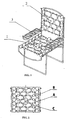
- Design solution of supporting surface of a deck-chair seat, back and arm-rest is reduced to a line assembly of specially arranged balls of different sizes. They are elastically linked together with corrosion-resistant wires or ropes made of steel (hereinafter inox-wire cable) within hard, supportive frame to which the balls are fixed.
- the special arrangement of balls of different sizes, on riding saddle principle, is chosen to enable anatomic adaptation, for comfortable sitting.
- the elasticity of the assembly itself is achieved by special linking of the balls, without using any element having elastic quality (such as springs, threads, balls, and shock absorbers).
- the invention consists of three basic elements (A, B, and C), where on the chair example, seat (1), back of seat (2) and arm-rest (3) are put together:
- the assembly described in item 4 (the invention essence display) that is formed of various sizes of balls, according to the arrangement showed in figure 2, should be linked with two inox-wire cable.
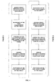
- the balls In the first phase the balls are strung up on the first inox-wire cable in order to form lines of balls between the frame, and then in the second phase the same balls are linked by pulling another inox-wire cable through them, in direction of so formed columns.
- the first inox-wire cable (C1) is led through transversal hole (A0) of the frame (A) in figure 3 beginning from the right side of the frame, with set fixing device (D) at its end in order to prevent pulling out the wire out of the frame (A).
- inox-wire cable (C1) from the outer side of the frame (A) is led into the first transversal hole (A0) in the frame, and is pulled through starting from the left side to the right side through the central holes of all balls (B0), and by stringing balls on the wire cable forming the second line of balls of the following order: B1-B2-B3-B3-B3-B2-B1, and then wire is going out through the hole (A0) on the opposite side of the frame (A).
- Inox-wire cable (C2) is led through the central hole (B0) of the first little ball (B1) in the first longitudinal line of balls and is led forward through all first balls (B1) in next lines, thus forming a column in the following order:
- leading of the second wire cable ends on the lower side of the right frame after going through last ball (B1) in a lower line, and going out through last transversal hole of the frame, where inox- wire cable should be fixed.
- An additional advantage of the invention that's not object of solving given technical problem, that it's about special design solution for manual instalment that offers production possibility, in the first place, in the cottage industry.
- the manual instalment of the line of balls on home working principle with personal organisation advantage of spatial work conditions and arbitrary working hours enables people an additional source of income and giving all capable members of the family a chance to participate.
- the social-economic dimension is achieved, promising to this today's neglected kind of technology, in combination with multi-serial industrial production of elements for instalment (small balls, frames and inox-cable wires) exceptional results.
Landscapes
- Massaging Devices (AREA)
- Compositions Of Macromolecular Compounds (AREA)
- Connection Of Plates (AREA)
- Chair Legs, Seat Parts, And Backrests (AREA)
- Pinball Game Machines (AREA)
- Springs (AREA)
Claims (6)
- Ein aus Kugeln bestehendes Gefüge als ein Element eines Liegestuhlsitzes (1), einer Rücklehne (2) und einer Armlehne (3), wobei die Elemente aus einem Rahmen (A) mit quer eingestochenen Löchern (AO) und zwei Verbindungselementen (c1, c2) in Form eines Drahtes oder einer Linie bestehen, auf dem bzw. der Kugeln (B) mit mittleren Löchern aufgereiht sind, wobei ein erstes Verbindungselement (c1) eine Linie bildet und zwischen gegenüberliegenden Seiten des Rahmens (A) verbindet, und wobei ein zweites Verbindungselement (c2) die Kugeln (B) auf eine Art und Weise verbindet, um in Bezug auf die Linie Spalten zu bilden, und zwar mit Befestigungselementen (D) an beiden Enden davon, um mit dem Rahmen (A) zu verbinden.
- Das aus Kugeln bestehende Gefüge als Element eines Liegestuhlsitzes (1), einer Rücklehne (2) und einer Armlehne (3) nach Anspruch 1, worin der Rahmen (A) ein harter Rahmen ist, der aus einem massiven oder hohlen Material, vorzugsweise Metall, gemacht ist, worin die Kugeln (B) unterschiedliche Größen (B1, B2, B3) haben und aus einem harten Material, vorzugsweise Holz mit einer glatten Oberfläche, gemacht sind, worin das Verbindungselement (C), das die Draht- oder Linienform hat, vorzugsweise ein Inoxdraht-Kabel ist und worin das Befestigungselement (D) trennbar und vorzugsweise ein Standard-Festspannelement ist.
- Ein Verfahren zum Verbinden eines aus Kugeln bestehenden Gefüges als Element eines Liegestuhlsitzes (1), einer Rücklehne (2) und einer Armlehne (3), das aus einem Rahmen (A) mit quer eingestochenen Löchern (AO) und zwei Verbindungselementen (C) in Form eines Drahtes oder einer Linie besteht, und zwar mit Befestigungselementen (D) an beiden Enden davon, um mit dem Rahmen (A) zu verbinden, und auf dem bzw. der Kugeln (B) mit mittleren Löchern (BO) aufgereiht sind, worin das Verfahren folgende Schritte umfasst:das Bilden einer aus Kugeln gemachten Linie, indem die Kugeln (B) auf einem ersten Inoxdraht-Kabel (C1) der Verbindungselemente (C) aufgereiht werden und ihre Verbindung zwischen gegenüberliegenden Seiten des Rahmens (A); unddas Bilden einer aus Kugeln gemachten Spalte und ihre Verbindung, indem das zweite Inoxdraht-Kabel (C2) der Verbindungselemente (C) durch die Kugeln (B) und den Rahmen (A) geführt wird.
- Das Verfahren nach Anspruch 3, worin die Kugeln (B) unterschiedliche Größen, nämlich eine erste Größe B1, eine zweite Größe B2 und eine dritte Größe B3, haben, und das weiterhin die folgenden Schritte umfasst:a) das Führen des ersten Inox-Drahtkabels (C1) durch ein quer eingestochenes Loch (AO) auf dem Rahmen (A), beginnend an der rechten Seite des Rahmens (A), und das Befestigen des ersten Endes des ersten Inoxdraht-Kabels (C1), um zu verhindern, dass es aus dem Rahmen (A) herausgezogen wird;b) das Aufreihen der Kugeln (B) auf dem ersten Inoxdraht-Kabel (C1), so dass eine erste Linie aus Kugeln (B) in folgender Reihenfolge der Größen gebildet wird: B1-B2-B3-B1-B3-B2-B1, beginnend von rechts nach links;c) das Ziehen des ersten Kabels (C1) durch ein quer eingestochenes Loch (AO) auf der linken Seite des Rahmens (A);d) das Führen des ersten Inoxdraht-Kabels (C1) durch die Außenseite des Rahmens (A) in ein quer eingestochenes Loch (AO) im Rahmen (A) auf seiner linken Seite;e) das Aufreihen der Kugeln (B) auf dem ersten Inoxdraht-Kabel (C1), so dass eine zweite Linie aus Kugeln (B) in folgender Reihenfolge der Größen gebildet wird: B1-B2-B3-B3-B3-B2-B1, beginnend von links nach rechts;f) das Ziehen des ersten Kabels (C1) durch ein quer eingestochenes Loch (AO) auf der rechten Seite des Rahmens (A);g) das Führen des ersten Inoxdraht-Kabels (C1) durch die Außenseite des Rahmens (A) in ein quer eingestochenes Loch (AO) im Rahmen (A) auf seiner rechten Seite;
das Wiederholen der Schritte b) bis g), um folgendes zu bilden:eine dritte Linie aus Kugeln (B) in der folgenden Reihenfolge der Größen: B1-B2-B3-B3-B3-B2-B1 von rechts nach links,eine vierte Linie aus Kugeln (B) in der folgenden Reihenfolge der Größen: B1-B2-B3-B1-B3-B2-B1 von links nach rechts,eine fünfte Linie aus Kugeln (B) in der folgenden Reihenfolge der Größen: B1-B2-B3-B1-B3-B2-B1 von rechts nach links,eine sechste Linie aus Kugeln (B) in der folgenden Reihenfolge der Größen: B1-B2-B3-B3-B3-B2-B1 von links nach rechts, undeine siebte Linie aus Kugeln (B) in der folgenden Reihenfolge der Größen: B1-B2-B3-B3-B3-B2-B1 von rechts nach links; undh) das Befestigen des zweiten Endes des ersten Inoxdraht-Kabels (C1), um das erste Inoxdraht-Kabel (C1) im Rahmen (A) zu verriegeln. - Das Verfahren nach Anspruch 3, worin die Kugeln (B) unterschiedliche Größen, nämlich eine erste Größe B1, eine zweite Größe B2 und eine dritte Größe B3, haben, und das weiterhin folgende Schritte umfasst:a) das Führen des zweiten Inoxdraht-Kabels (C2) durch ein quer eingestochenes Loch (AO) am Rahmen (A), beginnend an der oberen linken Seite des Rahmens (A), und das Befestigen des ersten Endes des zweiten Inoxdraht-Kabels (C2), um zu verhindern, dass es aus dem Rahmen (A) herausgezogen wird;b) das Verbinden einer ersten Spalte aus Kugeln (B) mittels des sich durch die mittleren Löcher (BO) der ersten Spalte aus Kugeln (B) schlängelnden zweiten Inoxdraht-Kabels (C2), wobei sich die erste Spalte aus Kugeln (B) aus einer ungeraden Anzahl an Kugeln (B) der ersten Größe B1 zusammensetzt;c) das Verbinden einer zweiten Spalte aus Kugeln (B) mittels des sich durch die mittleren Löcher (BO) der zweiten Spalte aus Kugeln (B) schlängelnden zweiten Inoxdraht-Kabels (C2), wobei sich die zweite Spalte aus Kugeln (B) aus einer ungeraden Anzahl an Kugeln (B) der zweiten Größe B2 zusammensetzt;d) das Verbinden einer dritten Spalte aus Kugeln (B) mittels des sich durch die mittleren Löcher (BO) der dritten Spalte aus Kugeln (B) schlängelnden zweiten Inoxdraht-Kabels (C2), wobei sich die dritte Spalte aus Kugeln (B) aus einer ungeraden Anzahl an Kugeln (B) der dritten Größe B3 zusammensetzt;e) das Verbinden einer vierten Spalte aus Kugeln (B) mittels des sich durch die mittleren Löcher (BO) der vierten Spalte aus Kugeln (B) schlängelnden zweiten Inoxdraht-Kabels (C2), wobei sich die vierte Spalte aus Kugeln (B) aus einer ungeraden Anzahl an Kugeln (B) unterschiedlicher Größe zusammensetzt;f) das Verbinden einer fünften Spalte aus Kugeln (B) mittels des sich durch die mittleren Löcher (BO) der fünften Spalte aus Kugeln (B) schlängelnden zweiten Inoxdraht-Kabels (C2), wobei sich die fünfte Spalte aus Kugeln (B) aus einer ungeraden Anzahl an Kugeln (B) der dritten Größe B3 zusammensetzt;g) das Verbinden einer sechsten Spalte aus Kugeln (B) mittels des sich durch die mittleren Löcher (BO) der sechsten Spalte aus Kugeln (B) schlängelnden zweiten Inoxdraht-Kabels (C2), wobei sich die sechste Spalte aus Kugeln (B) aus einer ungeraden Anzahl an Kugeln (B) der zweiten Größe B2 zusammensetzt;h) das Verbinden einer siebten Spalte aus Kugeln (B) mittels des sich durch die mittleren Löcher (BO) der siebten Spalte aus Kugeln (B) schlängelnden zweiten Inoxdraht-Kabels (C2), wobei sich die siebte Spalte aus Kugeln (B) aus einer ungeraden Anzahl an Kugeln (B) der ersten Größe B1 zusammensetzt;i) das Führen des zweiten Inoxdraht-Kabels (C2) durch ein quer eingestochenes Loch (AO) auf dem Rahmen (A), und zwar an der unteren rechten Seite des Rahmens (A), und das Befestigen des zweiten Endes des zweiten Inoxdraht-Kabels (C2), um das zweite Inoxdraht-Kabel (C2) im Rahmen (A) zu verriegeln.
- Das aus Kugeln bestehende Gefüge als Element eines Liegestuhlsitzes (1), einer Rücklehne (2) und einer Armlehne (3) nach Anspruch 1, worin der Aufbau einen Grundelement oder eine Komponente eines Produkts für Körpermassage oder Akupressur bereitstellt.
Applications Claiming Priority (3)
| Application Number | Priority Date | Filing Date | Title |
|---|---|---|---|
| HR20000915A HRP20000915B1 (en) | 2000-12-29 | 2000-12-29 | Assembly of balls as an element of deck-chair, chair, back of a chair and arm-rest, and the process of assembling thereof |
| HR20000915 | 2000-12-29 | ||
| PCT/HR2001/000037 WO2002052991A1 (en) | 2000-12-29 | 2001-07-20 | Assembly of balls as an element of deck-chair, chair, back of a chair and arm-rest, and the process of assembling thereof |
Publications (2)
| Publication Number | Publication Date |
|---|---|
| EP1345512A1 EP1345512A1 (de) | 2003-09-24 |
| EP1345512B1 true EP1345512B1 (de) | 2007-01-24 |
Family
ID=10947233
Family Applications (1)
| Application Number | Title | Priority Date | Filing Date |
|---|---|---|---|
| EP01949805A Expired - Lifetime EP1345512B1 (de) | 2000-12-29 | 2001-07-20 | Aus kugeln bestehendes gefüge als polsterelement eines sitzmöbels, und verfahren zu dessen herstellung |
Country Status (5)
| Country | Link |
|---|---|
| EP (1) | EP1345512B1 (de) |
| AT (1) | ATE352232T1 (de) |
| DE (1) | DE60126331T2 (de) |
| HR (1) | HRP20000915B1 (de) |
| WO (1) | WO2002052991A1 (de) |
Families Citing this family (6)
| Publication number | Priority date | Publication date | Assignee | Title |
|---|---|---|---|---|
| AT510214B1 (de) * | 2010-04-16 | 2012-10-15 | Martin Rille | Sitzinstrument |
| JP6926898B2 (ja) * | 2017-09-27 | 2021-08-25 | トヨタ紡織株式会社 | 着座用シート |
| JP6926897B2 (ja) * | 2017-09-27 | 2021-08-25 | トヨタ紡織株式会社 | 着座用シート |
| FR3087718B1 (fr) * | 2018-10-24 | 2020-10-16 | Faurecia Interieur Ind | Accoudoir de vehicule |
| CN109984500A (zh) * | 2019-03-13 | 2019-07-09 | 上海摩伽智能家居有限公司 | 人体工学坐具 |
| CN114102502B (zh) * | 2021-11-16 | 2023-11-21 | 武汉点溪园生态景观发展有限公司 | 一种景观园林建造工程安装施工方法 |
Family Cites Families (4)
| Publication number | Priority date | Publication date | Assignee | Title |
|---|---|---|---|---|
| GB2143436B (en) * | 1983-07-19 | 1986-11-19 | Aleksandar Svetislav Jovanovic | Massage chair |
| DE4133568C1 (en) * | 1991-10-10 | 1993-05-19 | Horst 5060 Bergisch Gladbach De Baermann | Massage arrangement for seat in vehicle - has magnetic elements with collar for reception of coupling thread |
| JP2787424B2 (ja) | 1995-01-27 | 1998-08-20 | 株式会社シグマ | クッションマット |
| TW381996B (en) | 1997-10-21 | 2000-02-11 | Delta Tooling Co Ltd | Cushion and seat having a net-shaped skin |
-
2000
- 2000-12-29 HR HR20000915A patent/HRP20000915B1/xx not_active IP Right Cessation
-
2001
- 2001-07-20 DE DE60126331T patent/DE60126331T2/de not_active Expired - Fee Related
- 2001-07-20 EP EP01949805A patent/EP1345512B1/de not_active Expired - Lifetime
- 2001-07-20 AT AT01949805T patent/ATE352232T1/de not_active IP Right Cessation
- 2001-07-20 WO PCT/HR2001/000037 patent/WO2002052991A1/en not_active Ceased
Also Published As
| Publication number | Publication date |
|---|---|
| ATE352232T1 (de) | 2007-02-15 |
| WO2002052991A1 (en) | 2002-07-11 |
| EP1345512A1 (de) | 2003-09-24 |
| HRP20000915B1 (en) | 2008-06-30 |
| DE60126331T2 (de) | 2007-10-31 |
| DE60126331D1 (de) | 2007-03-15 |
| HRP20000915A2 (en) | 2002-06-30 |
Similar Documents
| Publication | Publication Date | Title |
|---|---|---|
| KR100905641B1 (ko) | 신축성 슬립커버 | |
| WO2000045672A3 (en) | Seating product with sinuous spring assemblies | |
| GB2443122A (en) | A load bearing body-support structure | |
| US20060181135A1 (en) | Furniture designed for sitting and having inner core support assembly | |
| US20040160109A1 (en) | Chair seat with firm but resilient front edge | |
| US6824221B1 (en) | Furniture | |
| WO2002052991A1 (en) | Assembly of balls as an element of deck-chair, chair, back of a chair and arm-rest, and the process of assembling thereof | |
| JPH0397415A (ja) | ソファー寄り掛かり部の可逆的に変形自在のフレーム | |
| KR102184795B1 (ko) | 착석감 및 탄성을 높인 의자 | |
| US4052104A (en) | Seating unit | |
| US6832401B2 (en) | Spring support system | |
| US5678261A (en) | Cushion device | |
| CN2270419Y (zh) | 经纬式网状座具内框 | |
| CN222675811U (zh) | 一种加强支撑组合弹簧的沙发 | |
| CN212698281U (zh) | 一种沙发弹簧框架 | |
| CN206079821U (zh) | 一种沙发 | |
| KR200284313Y1 (ko) | 탄력적으로 젖혀지는 등받이 프레임을 갖는 의자 프레임 | |
| KR900005960Y1 (ko) | 간이 의자의 골조 | |
| CN210493365U (zh) | 一种简洁折叠椅 | |
| JP3555104B2 (ja) | 椅子の背もたれ構造 | |
| CN203676583U (zh) | 弹性支撑座椅 | |
| JPH0439727Y2 (de) | ||
| CN2128082Y (zh) | 组合式多功能弹性透气垫 | |
| KR910004306Y1 (ko) | 조립식 시트 | |
| KR200435300Y1 (ko) | 의자 쿠숀부의 쿠숀플레이트 체결구조 |
Legal Events
| Date | Code | Title | Description |
|---|---|---|---|
| PUAI | Public reference made under article 153(3) epc to a published international application that has entered the european phase |
Free format text: ORIGINAL CODE: 0009012 |
|
| 17P | Request for examination filed |
Effective date: 20030618 |
|
| AK | Designated contracting states |
Kind code of ref document: A1 Designated state(s): AT BE CH CY DE DK ES FI FR GB GR IE IT LI LU MC NL PT SE TR |
|
| AX | Request for extension of the european patent |
Extension state: AL LT LV MK RO SI |
|
| GRAP | Despatch of communication of intention to grant a patent |
Free format text: ORIGINAL CODE: EPIDOSNIGR1 |
|
| GRAS | Grant fee paid |
Free format text: ORIGINAL CODE: EPIDOSNIGR3 |
|
| GRAA | (expected) grant |
Free format text: ORIGINAL CODE: 0009210 |
|
| AK | Designated contracting states |
Kind code of ref document: B1 Designated state(s): AT BE CH CY DE DK ES FI FR GB GR IE IT LI LU MC NL PT SE TR |
|
| PG25 | Lapsed in a contracting state [announced via postgrant information from national office to epo] |
Ref country code: CH Free format text: LAPSE BECAUSE OF FAILURE TO SUBMIT A TRANSLATION OF THE DESCRIPTION OR TO PAY THE FEE WITHIN THE PRESCRIBED TIME-LIMIT Effective date: 20070124 Ref country code: AT Free format text: LAPSE BECAUSE OF FAILURE TO SUBMIT A TRANSLATION OF THE DESCRIPTION OR TO PAY THE FEE WITHIN THE PRESCRIBED TIME-LIMIT Effective date: 20070124 Ref country code: LI Free format text: LAPSE BECAUSE OF FAILURE TO SUBMIT A TRANSLATION OF THE DESCRIPTION OR TO PAY THE FEE WITHIN THE PRESCRIBED TIME-LIMIT Effective date: 20070124 Ref country code: DK Free format text: LAPSE BECAUSE OF FAILURE TO SUBMIT A TRANSLATION OF THE DESCRIPTION OR TO PAY THE FEE WITHIN THE PRESCRIBED TIME-LIMIT Effective date: 20070124 Ref country code: FI Free format text: LAPSE BECAUSE OF FAILURE TO SUBMIT A TRANSLATION OF THE DESCRIPTION OR TO PAY THE FEE WITHIN THE PRESCRIBED TIME-LIMIT Effective date: 20070124 Ref country code: NL Free format text: LAPSE BECAUSE OF FAILURE TO SUBMIT A TRANSLATION OF THE DESCRIPTION OR TO PAY THE FEE WITHIN THE PRESCRIBED TIME-LIMIT Effective date: 20070124 |
|
| REG | Reference to a national code |
Ref country code: GB Ref legal event code: FG4D |
|
| REG | Reference to a national code |
Ref country code: CH Ref legal event code: EP |
|
| REG | Reference to a national code |
Ref country code: IE Ref legal event code: FG4D |
|
| REF | Corresponds to: |
Ref document number: 60126331 Country of ref document: DE Date of ref document: 20070315 Kind code of ref document: P |
|
| PG25 | Lapsed in a contracting state [announced via postgrant information from national office to epo] |
Ref country code: SE Free format text: LAPSE BECAUSE OF FAILURE TO SUBMIT A TRANSLATION OF THE DESCRIPTION OR TO PAY THE FEE WITHIN THE PRESCRIBED TIME-LIMIT Effective date: 20070424 |
|
| PG25 | Lapsed in a contracting state [announced via postgrant information from national office to epo] |
Ref country code: ES Free format text: LAPSE BECAUSE OF FAILURE TO SUBMIT A TRANSLATION OF THE DESCRIPTION OR TO PAY THE FEE WITHIN THE PRESCRIBED TIME-LIMIT Effective date: 20070505 |
|
| PG25 | Lapsed in a contracting state [announced via postgrant information from national office to epo] |
Ref country code: PT Free format text: LAPSE BECAUSE OF FAILURE TO SUBMIT A TRANSLATION OF THE DESCRIPTION OR TO PAY THE FEE WITHIN THE PRESCRIBED TIME-LIMIT Effective date: 20070625 |
|
| REG | Reference to a national code |
Ref country code: CH Ref legal event code: PL |
|
| NLV1 | Nl: lapsed or annulled due to failure to fulfill the requirements of art. 29p and 29m of the patents act | ||
| ET | Fr: translation filed | ||
| PLBE | No opposition filed within time limit |
Free format text: ORIGINAL CODE: 0009261 |
|
| STAA | Information on the status of an ep patent application or granted ep patent |
Free format text: STATUS: NO OPPOSITION FILED WITHIN TIME LIMIT |
|
| 26N | No opposition filed |
Effective date: 20071025 |
|
| PG25 | Lapsed in a contracting state [announced via postgrant information from national office to epo] |
Ref country code: BE Free format text: LAPSE BECAUSE OF FAILURE TO SUBMIT A TRANSLATION OF THE DESCRIPTION OR TO PAY THE FEE WITHIN THE PRESCRIBED TIME-LIMIT Effective date: 20070124 |
|
| PG25 | Lapsed in a contracting state [announced via postgrant information from national office to epo] |
Ref country code: GR Free format text: LAPSE BECAUSE OF FAILURE TO SUBMIT A TRANSLATION OF THE DESCRIPTION OR TO PAY THE FEE WITHIN THE PRESCRIBED TIME-LIMIT Effective date: 20070425 Ref country code: MC Free format text: LAPSE BECAUSE OF NON-PAYMENT OF DUE FEES Effective date: 20070731 |
|
| PG25 | Lapsed in a contracting state [announced via postgrant information from national office to epo] |
Ref country code: IE Free format text: LAPSE BECAUSE OF NON-PAYMENT OF DUE FEES Effective date: 20070720 |
|
| PG25 | Lapsed in a contracting state [announced via postgrant information from national office to epo] |
Ref country code: CY Free format text: LAPSE BECAUSE OF FAILURE TO SUBMIT A TRANSLATION OF THE DESCRIPTION OR TO PAY THE FEE WITHIN THE PRESCRIBED TIME-LIMIT Effective date: 20070124 |
|
| PG25 | Lapsed in a contracting state [announced via postgrant information from national office to epo] |
Ref country code: LU Free format text: LAPSE BECAUSE OF NON-PAYMENT OF DUE FEES Effective date: 20070720 |
|
| PG25 | Lapsed in a contracting state [announced via postgrant information from national office to epo] |
Ref country code: TR Free format text: LAPSE BECAUSE OF FAILURE TO SUBMIT A TRANSLATION OF THE DESCRIPTION OR TO PAY THE FEE WITHIN THE PRESCRIBED TIME-LIMIT Effective date: 20070124 |
|
| PGFP | Annual fee paid to national office [announced via postgrant information from national office to epo] |
Ref country code: FR Payment date: 20090729 Year of fee payment: 9 |
|
| PGFP | Annual fee paid to national office [announced via postgrant information from national office to epo] |
Ref country code: DE Payment date: 20090730 Year of fee payment: 9 Ref country code: GB Payment date: 20090729 Year of fee payment: 9 |
|
| PGFP | Annual fee paid to national office [announced via postgrant information from national office to epo] |
Ref country code: IT Payment date: 20090824 Year of fee payment: 9 |
|
| GBPC | Gb: european patent ceased through non-payment of renewal fee |
Effective date: 20100720 |
|
| REG | Reference to a national code |
Ref country code: FR Ref legal event code: ST Effective date: 20110331 |
|
| PG25 | Lapsed in a contracting state [announced via postgrant information from national office to epo] |
Ref country code: DE Free format text: LAPSE BECAUSE OF NON-PAYMENT OF DUE FEES Effective date: 20110201 |
|
| REG | Reference to a national code |
Ref country code: DE Ref legal event code: R119 Ref document number: 60126331 Country of ref document: DE Effective date: 20110201 |
|
| PG25 | Lapsed in a contracting state [announced via postgrant information from national office to epo] |
Ref country code: IT Free format text: LAPSE BECAUSE OF NON-PAYMENT OF DUE FEES Effective date: 20100720 Ref country code: FR Free format text: LAPSE BECAUSE OF NON-PAYMENT OF DUE FEES Effective date: 20100802 |
|
| PG25 | Lapsed in a contracting state [announced via postgrant information from national office to epo] |
Ref country code: GB Free format text: LAPSE BECAUSE OF NON-PAYMENT OF DUE FEES Effective date: 20100720 |