EP1345657B1 - Ultraschallunterstütze lipolyse - Google Patents
Ultraschallunterstütze lipolyse Download PDFInfo
- Publication number
- EP1345657B1 EP1345657B1 EP01272231A EP01272231A EP1345657B1 EP 1345657 B1 EP1345657 B1 EP 1345657B1 EP 01272231 A EP01272231 A EP 01272231A EP 01272231 A EP01272231 A EP 01272231A EP 1345657 B1 EP1345657 B1 EP 1345657B1
- Authority
- EP
- European Patent Office
- Prior art keywords
- transducer
- focal zone
- tissue
- acoustic energy
- focal
- Prior art date
- Legal status (The legal status is an assumption and is not a legal conclusion. Google has not performed a legal analysis and makes no representation as to the accuracy of the status listed.)
- Expired - Lifetime
Links
- 238000002604 ultrasonography Methods 0.000 title description 14
- 230000004130 lipolysis Effects 0.000 title description 6
- 210000001519 tissue Anatomy 0.000 claims abstract description 74
- 230000006378 damage Effects 0.000 claims abstract description 20
- 206010033675 panniculitis Diseases 0.000 claims abstract description 15
- 210000004304 subcutaneous tissue Anatomy 0.000 claims abstract description 14
- 238000010438 heat treatment Methods 0.000 claims abstract description 6
- 230000001276 controlling effect Effects 0.000 abstract description 4
- 230000002596 correlated effect Effects 0.000 abstract description 2
- 210000003491 skin Anatomy 0.000 description 42
- 210000004027 cell Anatomy 0.000 description 28
- 210000000577 adipose tissue Anatomy 0.000 description 22
- 239000010410 layer Substances 0.000 description 20
- 238000000034 method Methods 0.000 description 14
- 238000012544 monitoring process Methods 0.000 description 13
- 239000007789 gas Substances 0.000 description 12
- 210000001789 adipocyte Anatomy 0.000 description 10
- 238000007443 liposuction Methods 0.000 description 9
- 239000000463 material Substances 0.000 description 7
- 239000012530 fluid Substances 0.000 description 5
- 239000004020 conductor Substances 0.000 description 4
- XLYOFNOQVPJJNP-UHFFFAOYSA-N water Substances O XLYOFNOQVPJJNP-UHFFFAOYSA-N 0.000 description 4
- 230000000740 bleeding effect Effects 0.000 description 3
- 230000008878 coupling Effects 0.000 description 3
- 238000010168 coupling process Methods 0.000 description 3
- 238000005859 coupling reaction Methods 0.000 description 3
- 210000004207 dermis Anatomy 0.000 description 3
- 210000002615 epidermis Anatomy 0.000 description 3
- 239000007788 liquid Substances 0.000 description 3
- 230000010363 phase shift Effects 0.000 description 3
- IJGRMHOSHXDMSA-UHFFFAOYSA-N Atomic nitrogen Chemical compound N#N IJGRMHOSHXDMSA-UHFFFAOYSA-N 0.000 description 2
- NNJVILVZKWQKPM-UHFFFAOYSA-N Lidocaine Chemical compound CCN(CC)CC(=O)NC1=C(C)C=CC=C1C NNJVILVZKWQKPM-UHFFFAOYSA-N 0.000 description 2
- 206010028980 Neoplasm Diseases 0.000 description 2
- 230000003444 anaesthetic effect Effects 0.000 description 2
- 239000012829 chemotherapy agent Substances 0.000 description 2
- 210000002808 connective tissue Anatomy 0.000 description 2
- 230000000875 corresponding effect Effects 0.000 description 2
- 238000012977 invasive surgical procedure Methods 0.000 description 2
- 229960004194 lidocaine Drugs 0.000 description 2
- 238000002844 melting Methods 0.000 description 2
- 230000008018 melting Effects 0.000 description 2
- 238000013021 overheating Methods 0.000 description 2
- 238000000527 sonication Methods 0.000 description 2
- 238000001356 surgical procedure Methods 0.000 description 2
- 230000000699 topical effect Effects 0.000 description 2
- 239000005526 vasoconstrictor agent Substances 0.000 description 2
- 229920002799 BoPET Polymers 0.000 description 1
- 206010020843 Hyperthermia Diseases 0.000 description 1
- 239000005041 Mylar™ Substances 0.000 description 1
- 206010042618 Surgical procedure repeated Diseases 0.000 description 1
- 210000004204 blood vessel Anatomy 0.000 description 1
- 230000037237 body shape Effects 0.000 description 1
- 238000010276 construction Methods 0.000 description 1
- 239000002537 cosmetic Substances 0.000 description 1
- 230000003247 decreasing effect Effects 0.000 description 1
- 230000001934 delay Effects 0.000 description 1
- 230000001419 dependent effect Effects 0.000 description 1
- 239000002961 echo contrast media Substances 0.000 description 1
- 230000029142 excretion Effects 0.000 description 1
- 239000011796 hollow space material Substances 0.000 description 1
- 230000036031 hyperthermia Effects 0.000 description 1
- 239000004615 ingredient Substances 0.000 description 1
- 230000001788 irregular Effects 0.000 description 1
- 150000002632 lipids Chemical class 0.000 description 1
- 230000007246 mechanism Effects 0.000 description 1
- 239000012528 membrane Substances 0.000 description 1
- DJGAAPFSPWAYTJ-UHFFFAOYSA-M metamizole sodium Chemical compound [Na+].O=C1C(N(CS([O-])(=O)=O)C)=C(C)N(C)N1C1=CC=CC=C1 DJGAAPFSPWAYTJ-UHFFFAOYSA-M 0.000 description 1
- 239000004005 microsphere Substances 0.000 description 1
- 230000017074 necrotic cell death Effects 0.000 description 1
- 230000002956 necrotizing effect Effects 0.000 description 1
- 210000005036 nerve Anatomy 0.000 description 1
- 229910052757 nitrogen Inorganic materials 0.000 description 1
- 230000003287 optical effect Effects 0.000 description 1
- 230000000149 penetrating effect Effects 0.000 description 1
- 239000002985 plastic film Substances 0.000 description 1
- 229920001296 polysiloxane Polymers 0.000 description 1
- 239000004800 polyvinyl chloride Substances 0.000 description 1
- 238000010008 shearing Methods 0.000 description 1
- 239000002356 single layer Substances 0.000 description 1
- 239000007787 solid Substances 0.000 description 1
- 125000006850 spacer group Chemical group 0.000 description 1
- 238000007920 subcutaneous administration Methods 0.000 description 1
- 210000004003 subcutaneous fat Anatomy 0.000 description 1
- 238000009210 therapy by ultrasound Methods 0.000 description 1
- 239000012780 transparent material Substances 0.000 description 1
- 230000000472 traumatic effect Effects 0.000 description 1
Images




Classifications
-
- A—HUMAN NECESSITIES
- A61—MEDICAL OR VETERINARY SCIENCE; HYGIENE
- A61B—DIAGNOSIS; SURGERY; IDENTIFICATION
- A61B17/00—Surgical instruments, devices or methods
- A61B17/22—Implements for squeezing-off ulcers or the like on inner organs of the body; Implements for scraping-out cavities of body organs, e.g. bones; for invasive removal or destruction of calculus using mechanical vibrations; for removing obstructions in blood vessels, not otherwise provided for
- A61B17/22004—Implements for squeezing-off ulcers or the like on inner organs of the body; Implements for scraping-out cavities of body organs, e.g. bones; for invasive removal or destruction of calculus using mechanical vibrations; for removing obstructions in blood vessels, not otherwise provided for using mechanical vibrations, e.g. ultrasonic shock waves
- A61B17/22012—Implements for squeezing-off ulcers or the like on inner organs of the body; Implements for scraping-out cavities of body organs, e.g. bones; for invasive removal or destruction of calculus using mechanical vibrations; for removing obstructions in blood vessels, not otherwise provided for using mechanical vibrations, e.g. ultrasonic shock waves in direct contact with, or very close to, the obstruction or concrement
-
- A—HUMAN NECESSITIES
- A61—MEDICAL OR VETERINARY SCIENCE; HYGIENE
- A61B—DIAGNOSIS; SURGERY; IDENTIFICATION
- A61B17/00—Surgical instruments, devices or methods
- A61B17/22—Implements for squeezing-off ulcers or the like on inner organs of the body; Implements for scraping-out cavities of body organs, e.g. bones; for invasive removal or destruction of calculus using mechanical vibrations; for removing obstructions in blood vessels, not otherwise provided for
- A61B17/22004—Implements for squeezing-off ulcers or the like on inner organs of the body; Implements for scraping-out cavities of body organs, e.g. bones; for invasive removal or destruction of calculus using mechanical vibrations; for removing obstructions in blood vessels, not otherwise provided for using mechanical vibrations, e.g. ultrasonic shock waves
- A61B2017/22005—Effects, e.g. on tissue
- A61B2017/22007—Cavitation or pseudocavitation, i.e. creation of gas bubbles generating a secondary shock wave when collapsing
-
- A—HUMAN NECESSITIES
- A61—MEDICAL OR VETERINARY SCIENCE; HYGIENE
- A61N—ELECTROTHERAPY; MAGNETOTHERAPY; RADIATION THERAPY; ULTRASOUND THERAPY
- A61N7/00—Ultrasound therapy
- A61N2007/0004—Applications of ultrasound therapy
- A61N2007/0008—Destruction of fat cells
-
- A—HUMAN NECESSITIES
- A61—MEDICAL OR VETERINARY SCIENCE; HYGIENE
- A61N—ELECTROTHERAPY; MAGNETOTHERAPY; RADIATION THERAPY; ULTRASOUND THERAPY
- A61N7/00—Ultrasound therapy
- A61N2007/0078—Ultrasound therapy with multiple treatment transducers
-
- A—HUMAN NECESSITIES
- A61—MEDICAL OR VETERINARY SCIENCE; HYGIENE
- A61N—ELECTROTHERAPY; MAGNETOTHERAPY; RADIATION THERAPY; ULTRASOUND THERAPY
- A61N7/00—Ultrasound therapy
Definitions
- the invention relates generally to systems and devices for destroying tissue using focused ultrasound, and more particularly to systems and devices for destroying tissue by focusing ultrasound from an external source towards subcutaneous tissues, such as adipose tissue to aid in body contouring.
- Liposuction is a commonly used cosmetic surgical procedure for removing fat (adipose) cells to achieve a more desirable body shape.
- Liposuction usually involves an invasive surgical procedure, which includes penetrating the skin, melting or shearing the adipose tissue, and mechanically removing the adipose tissue using a vacuum or other suctioning device.
- Tumescent liposuction is a common variation in which "tumescent" solution is introduced into a target tissue region, e.g., a layer of fatty tissue, to loosen the structure of the fatty tissue and to facilitate its suction.
- the tumescent solution generally includes, among other possible ingredients, a topical anesthetic, such as lidocaine, and a vasoconstrictor to reduce bleeding, such as Norinephrine.
- a large quantity of tumescent solution is infiltrated, e.g., in a one-to-one ratio with the fat to be removed, causing the tissue region to swell.
- Suction is then performed using a special cannula connected to a vacuum system that is introduced into the fatty layer through incisions in the patient's skin, typically three to six millimeters (3-6 mm) wide.
- the cannula is moved around inside each incision to reach target sites within the tissue region that are to be removed.
- ultrasound assisted liposuction involves introducing a solid stick ultrasound transducer through an incision in the patient's skin and moving the transducer through a fatty tissue region.
- the transducer emits ultrasonic energy, generally at frequencies of 20-30 kHz, that may heat the tissue in the region until necrosis occurs, and/or may cause cavitation, thereby rupturing adipose cells in the region.
- a cannula is introduced into the tissue region to perform suction, as described above.
- a hollow transducer may be used that provides suction simultaneously with the delivery of ultrasonic energy.
- the transducer may become quite hot during its use. This may result in damage or destruction of tissues adjacent to the target region by overheating or melting.
- the transducer may be introduced through the skin using an insulated sleeve, although this may require a much larger incision, e.g., about ten millimeters (10 mm) or more wide.
- the doctor may need to use extreme care and keep moving the transducer in order to avoid burning tissue.
- treatment may also be limited to direct contact between the transducer and the adipose tissue, possibly resulting in non-uniform destruction of fat cells in the target region.
- U.S. Patent No. 5,884,631 issued to Silberg, discloses using an external ultrasonic generator to transmit ultrasound waves through a patient's skin to underlying adipose tissue.
- Silberg proposes using ultrasonic energy at a frequency above about twenty kilohertz to disrupt the connective tissue between fat cells, whereupon conventional liposuction may be used to remove the cells.
- the ultrasound energy in Silberg is not focused, but instead is delivered from a point contact,on the surface of a patient's skin indiscriminately into the underlying tissue.
- Such unfocused ultrasonic energy may be ineffective for facilitating liposuction since the energy is merely diffused generally into the underlying tissue.
- U.S. Patent No. 5,143,063 issued to Fellner, discloses a device and method for necrosing adipose tissue by directing radiant energy directly to a tissue region or work site.
- radiant energy such as radio frequency, microwave, or ultrasonic energy
- the only specific examples given for focusing ultrasonic energy at a subcutaneous tissue region involve using a concave lens or a Barone reflector.
- a concave lens or a Barone reflector may have a fixed "focal distance,” i.e., the distance from the device to the "focal zone,” i.e., the region to which the energy is focused.
- such devices may only generate a relatively small focal zone having a fixed size and shape.
- the exemplary procedure suggested by Fellner involves focusing energy at a work site for at least about thirty to forty minutes in order to effectively heat and necrose tissue at the work site.
- the suggested procedures may be time-consuming and/or may risk heating or damaging tissue outside the work site.
- US 5 209 221 according to the preamble of claim 1 discloses a device for non-hyperthermically acting treatment of small regions of tissue.
- the invention relates generally to systems and devices for focusing ultrasound energy from a location external to a patient to rupture or otherwise remove cells, such as adipose cells, within a subcutaneous tissue region.
- the invention may minimize damage, such as that caused by invasive surgical procedures and/or by heating of neighboring tissues when unfocused ultrasound is indiscriminately introduced into a tissue region.
- the target cells preferably adipose cells, may be ruptured and then removed, for example, by natural excretion mechanisms within the body or by gentle suction.
- a transducer is disposed externally adjacent to the patient's skin.
- the transducer is driven with drive signals such that the transducer emits acoustic energy, while the acoustic energy is focused at a focal zpne within a target tissue region.
- the acoustic energy preferably ultrasonic energy, has sufficient intensity to vibrate, cavitate, and/or otherwise mechanically damage fluid within the focal zone, thereby rupturing or otherwise destroying tissue, e.g., adipose cells, within the focal zone.
- the ultrasonic energy is preferably applied using a relatively low duty cycle, i.e., in short bursts relative to the time between successive bursts to limit the amount of heating of tissue in and around the target tissue region.
- the transducer may be operated using a duty cycle of about twenty percent (20%) or less, preferably about ten percent (10%) or less, and more preferably about one percent (1%) or less.
- the transducer may emit ultrasonic energy at a frequency range between about two and ten megahertz (2-10 MHz), and more preferably between about four and six megahertz (4-6 MHz).
- the transducer may have either a fixed focal distance or a variable focal distance.
- “Focal distance” is the distance from an acoustic emission surface of the transducer to a center of the "focal zone," i.e., the region where energy from the transducer is focused.
- the transducer is configured for producing a substantially linear focal zone.
- the transducer may have a single transducer element, thereby having a fixed focal distance.
- a single partial cylindrical transducer may be provided that focuses ultrasonic energy due to its geometry, or a substantially planar transducer may be provided that includes a lens for focusing the ultrasonic energy at a desired focal zone.
- the transducer may include a phased array.
- the transducer may include a plurality of linear transducer elements disposed adjacent to one another, e.g., in a partial cylindrical arrangement or in a substantially planar arrangement.
- the transducer may include a plurality of transducer elements defining respective portions of a single arc, each of which is projected onto a plane.
- the plurality of transducer elements may be arranged in a configuration similar to a Fresnel lens.
- Such a transducer configuration may substantially minimize the space between the acoustic emission surface of the transducer and the patient's skin, facilitating acoustically coupling the transducer to the patient and/or minimizing air gaps between the transducer and the patient's skin.
- Drive circuitry is coupled to each individual transducer element, the drive circuitry being controlled by a controller.
- Drive signals from the drive circuitry cause the transducer element(s) to emit ultrasonic energy.
- the controller may control a phase shift value of respective drive signals to the transducer elements, thereby adjusting a focal distance to the focal zone.
- a transducer array may be provided that generates multiple simultaneous focal zones.
- These systems may include a plurality of individual transducers that are disposed side-by-side in a substantially planar configuration, thereby being capable of generating a plurality of substantially parallel linear focal zones. Treatment time may be decreased with such a multiple-focal zone embodiment, as will be appreciated by those skilled in the art.
- a transducer may be provided that includes one or more detectors for measuring ultrasound signals produced during cavitation.
- cavitating gas bubbles produce a strong signal, for example, at a frequency of approximately one half of the transmitted ultrasound waves.
- An acoustic sensor such as a cavitation strip detector, may be provided on the transducer for detecting such cavitation signals.
- a monitoring system may be coupled to the detector for monitoring cavitation during a procedure.
- the system may include a processor that correlates the cavitation signals to determine the extent of cavitation, and consequently tissue destruction, occurring in the target tissue region.
- a rate of change in amplitude of the detected signals may be monitored to determine when cells within a target tissue region have been substantially destroyed.
- the amplitude of the cavitation signals may be integrated over time until a predetermined value is reached.
- the system may monitor the cavitation signals to ensure that a predetermined peak amplitude, i.e., rate of cavitation, is not exceeded, e.g., to provide a desired safety factor against excessive cavitation, which may be harmful to the patient.
- an apparatus may be provided for moving an ultrasound transducer (or a set of transducers) in a controlled manner.
- the transducer may be mounted to a frame that may be disposed adjacent the patient's skin.
- the transducer may be moved along the patient's skin, e.g., continuously or incrementally, to cavitate successively adjacent tissue regions, thereby providing a more uniform treatment.
- Figures 1 and 2 show a first preferred embodiment of a system 10 for treating tissue, in accordance with the invention.
- the system 10 includes a transducer 12, drive circuitry 14 coupled to the transducer 12, and a controller 16 coupled to the drive circuitry 14.
- the transducer 12 is generally made from piezoelectric material in a conventional manner, as is well known to those skilled in the art.
- the transducer 12 may emit acoustic energy from surface 18, as illustrated by exemplary acoustic waves 20.
- the transducer 12 has a single transducer element defining an arcuate cross-section that extends substantially parallel to a longitudinal axis 22 of the transducer 12.
- the surface 18 defines a portion of a cylinder, preferably having a substantially constant radius of curvature.
- the cross-section of the surface 18 may define a portion of another generally concave curve.
- the transducer 12 preferably has a base length 24 of between about five and fifteen centimeters (5-15 cm), and a base width 26 of between about one and four centimeters (1-4 cm).
- the focal zone 28 has a substantially linear shape that extends substantially parallel to the longitudinal axis 22, as described further below. Because the transducer 12 has only a single transducer element, a "focal distance" 30, i.e., a distance from the surface 18 to a center of the focal zone 28 along axis "z," is substantially fixed by the geometry of the transducer 12. For example, for a constant radius transducer, the focal distance 30 may correspond substantially to a geometric focus of the transducer 12.
- the drive circuitry 14 is coupled to the transducer 12 and provides drive signals 15 to the transducer 12 that cause the transducer 12 to emit acoustic energy.
- radio frequency (RF) drive signals 15 are used to excite the transducer 12 to emit ultrasonic energy at a predetermined amplitude, frequency, and wave shape.
- the drive signals 15 cause the transducer 12 to emit ultrasonic energy at a frequency between about two and ten Megahertz (2-10 MHz), and more preferably between about four and six Megahertz (4-6 MHz).
- the optimal frequency may be dependent upon the focal distance of the focal zone generated by the transducer. For example, if a longer focal distance is needed, relatively lower frequency drive signals may be preferred, e.g., to minimize dissipation in the intervening tissue, while for a relatively shorter focal distance, higher frequency drive signals may be preferred.
- the controller 16 is coupled to the drive circuitry 14 and controls various aspects of the drive signals 15 provided by the drive circuitry 14. For example, the controller 16 may adjust an amplitude of the drive signals 15, and consequently the amplitude of the acoustic waves 20. Preferably, as described further below, the controller 16 directs the drive circuitry 14 to cause the transducer 12 to emit acoustic energy at an amplitude or intensity sufficient to vibrate, cause cavitation, and/or otherwise cause mechanical damage, thereby destroying tissue, e.g., rupturing adipose cells, in the focal zone 28.
- the controller 16 activates the drive circuitry 14 such that the transducer 12 emits acoustic energy using a relatively low "duty cycle," i.e., a ratio between a time period that the transducer 12 is activated during a cycle and a time period of each cycle.
- the duty cycle may be about twenty percent (20%) or less, preferably about ten percent or less, and more preferably about one percent or less.
- the transducer may emit acoustic energy in relatively short bursts, each burst including only a few discrete wavelengths of acoustic energy, but having sufficient intensity to rupture cells within the focal zone, e.g.
- short-burst pulses may have a duration of between approximately 0.25 and 20 ⁇ sec may be emitted every 100 ⁇ sec during a single sonication. Because the acoustic energy is highly focused and of sufficient amplitude, these short bursts are adequate to rupture or otherwise destroy cells, e.g., adipose cells, in the focal zone 28.
- the time-average acoustic energy emitted by the transducer is relatively low, thereby minimizing the risk of heat build-up in or adjacent to the target tissue region, contrary to previously known hyperthermia techniques that use heating to necrose tissue.
- the transducer 12 is generally disposed in direct contact with a patient's skin 90.
- Gel or other acoustically conductive media may be provided between the transducer 12 and the patient's skin 90 to acoustically couple them.
- the acoustic gel fills a hollow space 32 between the transducer 12 and the patient's skin 90 to prevent discontinuities or irregularities in the ultrasonic energy emitted by the transducer 12 that passes through the patient's skin 90.
- the transducer 12 may be disposed within a casing, such as a flexible bag (not shown).
- An outer surface of the casing may be formed from an acoustically transparent material, such as a thin plastic sheet of mylar or polyvinyl chloride (PVC). More preferably, the outer surface may be substantially flexible to facilitate the casing conforming to the shape of a surface contacted by the casing, such as a patient's skin.
- the casing may be filled with degassed water, gel, or other acoustically conductive fluid to facilitate acoustically coupling the transducer to the patient's skin, as is well known in the art. Additional information on such a transducer and casing may be found in U.S. Patent No. 5,526,814.
- the transducer 12 is generally placed externally adjacent to the patient's skin 90.
- Gel or other acoustically conductive material (not shown) is placed between the transducer 12 and the patient's skin 90, as described above.
- the outer surface of the casing may be placed in contact with the patient's skin 90, possibly with water, gel, or other acoustically conductive material placed between the casing and the patient's skin 90 to provide additional acoustical coupling, if desired.
- the acoustically conductive material may act as a spacer to allow focusing of the acoustic energy at different depths within the tissue, as described further below.
- the patient's skin 90 includes a layer of epidermis overlying a layer of dermis 92, which, in turn, generally overlies a subcutaneous tissue layer including fatty (adipose) tissue 94.
- the transducer 12 is positioned a predetermined distance above the patient's skin 90 such that the focal zone 28 of the transducer 12 is positioned within the subcutaneous tissue region 94.
- the casing may be sufficiently flexible to accommodate a range of positions above the patient's skin 90 without decoupling the casing from the patient's skin 90.
- the transducer 12 is then activated, causing acoustic energy to penetrate through the epidermis and dermis 92 into the fatty tissue layer 94, and converge substantially at the focal zone 28.
- a "sonication” i.e., a single treatment during which acoustic energy is focused at a target tissue region for a set time period
- the transducer 12 may be activated for a plurality of successive relatively short bursts, as described above, to substantially destroy the tissue in the focal zone 28.
- “Cavitation” is a well-known phenomenon experienced when acoustic energy encounters matter.
- the acoustic energy causes gas bubbles dissolved in fluid within the tissue to "pop,” thereby releasing kinetic energy.
- the acoustic energy may be absorbed by water in tissue, causing gas bubbles dissolved in the water to rapidly contract and expand, and consequently explode or "pop.”
- other existing gas bubbles occurring within the tissue may be cavitated using acoustic energy. The released kinetic energy may rupture cells or loosen connective tissue adjacent to the cavitated gas bubbles.
- gas bubbles e.g., dissolved in a liquid
- a "tumescent" solution may be injected into the target tissue region that includes gas bubbles, such as air or Nitrogen, dissolved therein.
- the tumescent solution may also include a variety of known materials that may enhance a lipolysis procedure.
- the tumescent solution may include a topical anesthetic, such as lidocaine, or a vasoconstrictor, such as Norinephrine.
- the tumescent solution may help reduce pain to the patient, may reduce bleeding, may cause tissue within the target tissue region to swell, may help loosen fatty tissue, and the like, as is well known in the art.
- the tumescent solution may be injected into the target tissue region before the transducer is positioned adjacent the patient's skin. If the ultrasound treatment is to be followed by gentle suction, large quantities of tumescent solution may be infiltrated into the tissue, for example, in a one-to-one or less ratio with the fat tissue to be removed, e.g., to loosen the tissue.
- the kinetic energy released by the cavitating gas bubbles preferably causes the walls of cells in the focal zone, such as adipose cells, to rupture, releasing cell media into the interstitial space between the cells, e.g., causing the subcutaneous adipose tissue 145 to become emulsified.
- the transducer 12 may then be moved to another location, for example, adjacent to the first target tissue region, and the procedure repeated.
- gas bubble-containing fluids may be introduced.
- ultrasound contrast agents such as liquids including microspheres containing lipids or other materials, may be injected into the tissue region.
- free gas bubbles suspended in a liquid may be injected.
- the mechanical energy imposed on the cells from the acoustic energy may be of sufficient intensity that the resulting mechanical damage may cause the cells to rupture, either with or without cavitation also occurring.
- cavitation is merely a specific example of mechanical damage that may be imposed by the acoustic energy upon the cells in order to cause the cells to rupture.
- the transducer 12 is successively moved incrementally or continuously in a direction substantially perpendicular to its longitudinal axis 18 and activated, thereby causing cavitation or otherwise rupturing cells through a layer of subcutaneous tissue.
- the transducer 12 may be movably mounted to a frame 550, such as that shown in Figure 12, and described further below. This may allow the target cells to be ruptured in a substantially uniform manner until a generally planar layer of subcutaneous tissue, e.g., a layer of adipose tissue, is cavitated.
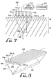
- a system 110 in accordance with the invention includes a transducer 112 having a single, substantially planar transducer element 134 and an acoustic lens 136.
- the system 110 also includes drive circuitry 14 and a controller 16, similar to the embodiment described above.
- the lens 136 is acoustically coupled to the transducer element 134, thereby focusing ultrasonic energy, represented by exemplary waves 120, emitted by the transducer element 134 at a focal zone 128.
- the lens 136 may be substantially permanently or detachably attached to the transducer element 134.
- the lens 136 may be spaced a predetermined distance from the transducer element 134, and an acoustically conductive material may be disposed between the transducer element 134 and the lens 136.
- the lens 136 defines a partial cylindrical emission surface 118, more preferably having an elongate concave shape, for focusing the acoustic energy generated by the transducer element 134 at a substantially linear focal zone 128 that extends substantially parallel to a longitudinal axis 122 of the transducer 112.
- the lens 136 has an elongate concave emission surface 118, although alternatively an elongate convex emission surface (not shown) may be provided depending upon the material of the lens 136.
- the transducer 134 may be moved closer or farther away from the patient's skin 90 to change the location of the focal zone 128 within the subcutaneous tissue region 94.
- the lens 136 may be replaced with another lens (not shown) having a different radius of curvature, to provide a desired focal distance 130 to the focal zone 128.
- an acoustic lens may be provided that allows adjustment of the focal distance, such as that disclosed in US 6554826.
- the transducer 212 includes a plurality of transducer elements (234-1 to 234-n), each transducer element 234 preferably extending substantially parallel to a longitudinal axis 222. More preferably, the transducer elements 234 are arranged in a linear configuration, i.e., side-by-side in a lengthwise manner, thereby together defining a partial cylindrical emission surface 218.
- a transducer 312 may include a plurality of transducer elements 334 disposed in a substantially planar configuration extending substantially parallel to longitudinal axis 322.
- the transducer 212 may be formed from a plurality of individual transducer elements 234 that are bonded together. Alternatively, the transducer 212 may be formed from a single piece of piezoelectric material, with grooves formed therein to separate and define each transducer element 234. Any spaces (not shown) between the transducer elements 234 may be filled with silicone and the like to substantially isolate the transducer elements 234 from one another, as is well known to those skilled in the art.
- the transducer 212 may include between about three and thirty, and preferably between three and ten, transducer elements 234.
- the drive circuitry 214 is individually coupled to each transducer element 234 to deliver respective drive signals 215 to the transducer elements 234.
- the controller 216 is coupled to the drive circuitry 214 for controlling several aspects of the drive signals 215 generated by the drive circuitry 214.
- the controller 216 may control the amplitude of the drive signals 215, for example, to control the intensity of ultrasonic energy delivered by the transducer 212, similar to the embodiments described above.
- the controller 216 may control a phase shift value between each of the transducer elements 234. For example, by shifting the phase between the transducer elements 234-1 to 234-n, the focal distance 230 to the focal zone 228 may be adjusted along the z-axis.
- the controller 216 may include a processor, such as a microcomputer (not shown), that is coupled to the drive circuitry 214 for controlling these aspects of its operation.
- FIG. 9 another embodiment of a system 410, in accordance with the invention, is shown that includes a transducer 412, drive circuitry 414, and a controller 416.
- the transducer 512 includes a plurality of transducer elements 434-1 to 434-n formed from piezoelectric material, similar to the embodiments described above.
- the transducer elements 434 have a cross-section corresponding substantially to respective portions of a cylinder 438 (shown in phantom) that are projected generally onto a plane (defined by the surface of the patient's skin 90 in Figure 9).
- the transducer 412 may include an emission surface 418 that corresponds substantially to a partial cylinder 438, but may substantially minimize a cavity 432 between the transducer 412 and the patient's skin 90.
- This configuration has a geometry somewhat similar to an optical lens, called a Fresnel lens, which is a transparent panel used to focus light passing through it.
- the drive circuitry 414 is coupled to the individual transducer elements 434 for supplying drive signals 415, similar to the embodiments described above.
- the transducer 412 emits acoustic energy similar to the partial cylinder 438, with the discontinuity between adjacent transducer elements being substantially negligible.
- the distance that the transducer elements 434 are projected from the partial cylinder 438 may require compensation to ensure proper focusing.
- the controller 416 controls the drive circuitry 414 to introduce phase shifts into the drive signals 415 to compensate for the distance between the transducer elements 434 and the portion of the partial cylinder 438 from which the respective transducer elements 434 are projected.
- the inner transducer elements 434-2 to 434-(n-1) may emit acoustic energy having predetermined delays relative to the outer transducer elements 434-1 and 434-n such that the acoustic energy delivered to focal zone 428 has similar properties to acoustic energy that would be emitted by the partial cylinder 438.
- the transducer 412 may be placed in contact with a patient's skin 90, with acoustic gel or similar material provided within the cavity 432 to acoustically couple the transducer 412 to the patient. Because of the substantially planar configuration of the transducer 412, significantly less acoustic gel may be required, thereby reducing the possibility of discontinuities between the transducer 412 and the patient's skin 90. Acoustic energy may then be delivered through the epidermis and dermis 92 into a subcutaneous fatty tissue layer 94 and focused at focal zone 428.
- the controller 416 may introduce phase shifting to compensate for the transducer configuration, as well as providing further phase shifting to control a focal distance 430 and/or size and shape of the focal zone 428, similar to the embodiments described above.
- a multiple element transducer device may be provided that is coupled to an acoustic lens having a configuration similar to a Fresnel lens.
- a transducer device (not shown) may be provided that includes a substantially planar transducer array, such as that shown in Figures 7 and 8.
- a lens configured similar to the transducer 412, may be coupled to the emission surface of such a transducer array to provide further focusing of acoustic energy emitted by the transducer array.
- transducer array 512 includes a plurality of transducers 534-1 to 534-p arranged side-by-side in a substantially planar configuration disposed substantially parallel to longitudinal axis 522.
- Each of the transducers 534 may be similar in construction to any of the transducers described above.
- the transducers 534 may be connected to one another and/or may be provided on a track, such as the frame described below.
- the transducer array 512 may be acoustically coupled to a patient (not shown), for example, by placing the transducers 534 in contact with or in close proximity to the patient's skin (also not shown). Any spaces between the transducers 534 and the skin may be filled with an appropriate acoustically conductive medium, such as an acoustic gel (not shown) that may have a density similar to the tissue being treated, e.g., adipose tissue.
- the transducers 534 may be activated to generate a plurality of substantially parallel focal zones 528-1 to 528-p.
- the transducer array 512 may be moved along the surface of the patient's skin, e.g., along a Y-axis, i.e., substantially perpendicular to the longitudinal axis 522 and z-axis, thereby rupturing or otherwise destroying a layer of tissue, e.g., a layer of adipose tissue (also not shown).
- transducer array 512 may only have to be moved a distance equal to a distance between adjacent transducers 534 in order to remove a layer of tissue beneath the transducer array 512. This may provide a significantly shorter treatment time than using a single transducer, as will be appreciated by those skilled in the art.
- transducer array 512' may include a plurality of transducers 534-1' to 534-n' that have progressively deeper focal distances 530-1' to 530'n'.
- the transducer array 512 is moved along a patient's skin 90, several layers of tissue within tissue region 94 may be substantially simultaneously cavitated.
- the transducer array may be provided within a fluid-filled casing (not shown), such as that described above, that may be placed in contact with a patient's skin.
- the transducer array may be moved within the casing, e.g. incrementally or continuously, substantially parallel to the surface of the patient's skin.
- a single layer or multiple layers of tissue may be removed without having to directly contact the patient's skin with the transducer or move the transducer directly along the patient's skin.
- the various embodiments of transducers described herein may be movably mounted to a frame 650.
- the frame 650 may include a pair of spaced apart rails 652 extending along a Y-axis of the frame 650.
- the transducer 612 may be slidably mounted to the rails 652,for example, in tracks (not shown).
- the frame 650 may be mounted within a casing (not shown) as described above.
- the frame 650 is substantially flat or is contoured similar to a corresponding region of a patient's body (also not shown). Thus, the transducer 612 may be moved along the rails while remaining substantially constantly in contact with the patient's body.
- the frame 650 may facilitate manual manipulation of the transducer 612 with respect to the patient's body.
- the transducer 612 may be coupled to the patient's skin (not shown), e.g., by providing acoustic gel and the like in the cavity 632 and/or elsewhere between the transducer 612 and the patient's skin.
- the transducer 612 may be moved along the frame 650 to a desired location, and then activated to cavitate or otherwise rupture cells of an underlying tissue region.
- the frame 650 may facilitate motorized and/or automatic operation of the transducer 612.
- a mechanical controller 664 e.g., including a motor (not shown), may be coupled to the frame 650, e.g., to the track (not shown) in the rails 652, or directly to the transducer 612.
- the controller 664 may allow the transducer 612 to be moved incrementally, continuously, and/or based upon desired feedback along the Y-axis, i.e., in a direction substantially perpendicular to a longitudinal axis 622 of the transducer 612.
- the transducer 612 may be automatically moved to a desired location, activated for a predetermined time, moved to an adjacent location, activated again, and so on to destroy or remove a layer of tissue, e.g., to provide a more uniform lipolysis of a layer of adipose tissue.
- cavitation detectors may be associated with any of the transducers described herein.
- the cavitation detectors may facilitate controlling a treatment, e.g., to more evenly and uniformly destroy a layer of tissue, or may be provided as a safety feature.
- cavitation strip detectors 660 may be provided on opposing edges of a transducer 612.
- the detectors 660 may be between about one and two millimeters (1-2 mm) wide, and may extend substantially the entire length of the transducer 612.
- the detectors 660 may be coupled to a monitoring system 662, e.g., for monitoring cavitation within the focal zone 628 of the transducer 612.
- the monitoring system 662 includes a meter (not shown), which may provide an output, e.g., on a gauge or other display, based upon signals detected by the detectors 660.
- a meter may provide an output, e.g., on a gauge or other display, based upon signals detected by the detectors 660.
- the meter may detect rupturing of the cells themselves, e.g., due to cavitation and/or other mechanical damage.
- the detectors 660 may be configured for detecting such cavitation signals produced at the focal zone 628 of the transducer 612.
- a physician performing a lipolysis procedure may monitor the cavitation signals using the detectors 660 to ensure that a desired level of cavitation is occurring and/or that a predetermined maximum level of cavitation is not exceeded.
- the monitoring system 662 may be coupled to a controller 616 and/or drive circuitry 614 that are used to drive the transducer 612.
- the monitoring system 662 may notify the controller 616 when a maximum level of cavitation is exceeded (which may be preset by the user), whereupon the controller 616 may direct the drive circuitry 614, to automatically discontinue drive signals 615 to the transducer 612.
- the controller 616 may then require resetting by the physician before the transducer 612 may be used for any further treatment, or the controller 616 may only discontinue the drive signals 615 for a predetermined time, e.g., to provide sufficient time for the tissue to recover.
- the detectors 660 may provide a desired safety factor during a treatment.
- the controller 616 may adjust an amplitude of the drive signals 615 in response to the cavitation signals detected by the detectors 660.
- the controller 616 may correlate the amplitude of the cavitation signals to an extent of cell destruction occurring at the focal zone 628. More preferably, the controller 616 may correlate a rate of change of amplitude of the cavitation signals over time to determine the extent that cells have been ruptured within the focal zone. Thus, if cavitation is occurring at too great a rate, which may excessively damage tissue in or adjacent to the focal zone, the amplitude of the drive signals 615 may be reduced accordingly.
- the monitoring system 662 may be coupled to a mechanical controller 664 for moving the transducer 612 within a frame 650.
- the intensity of the cavitation signals, and preferably a rate of change in intensity of the cavitation signals may be correlated to an empirical database to automatically determine when a desired level of cell destruction has occurred within the focal zone 628.
- the mechanical controller 664 may automatically move the transducer 612 to a new and/or adjacent location.
- the amplitude of the cavitation signals may be integrated over time until a predetermined value is reached, indicating that a desired level of cell destruction has occurred.
- the drive signals 615 to the transducer 612 may be discontinued until the transducer 612 is moved to the new location.
- cavitation strip detectors 660 may facilitate monitoring whether lipolysis is proceeding smoothly and substantially uniformly. As the transducer 612 is moved across a patient's skin (not shown) with the intention to destroy a substantially uniform layer of adipose tissue, it may be used to determine when the transducer should be moved to the next position.
- the monitoring system 662 may be coupled to the cavitation strip detectors 660 for correlating cavitation signals detected by the cavitation detectors to facilitate monitoring and/or ensuring a more even rupturing of cells within a layer of fatty tissue. Such a monitoring system 662 may facilitate more uniform cell destruction and may help deliver adequate energy to a given focal zone, thereby preventing overheating or corollary damage to neighboring tissues.
- the cavitation strip detectors 660 may provide real-time control and feedback for producing a more uniform removal of the adipose layer.
- the systems and devices of the invention may be used for treating a variety of subcutaneous tissues.
- the systems and devices of the invention may be used to destroy tumors within subcutaneous tissue, such as cancerous tumors, without invasive surgery.
- Chemotherapy agents may be introduced into a target tissue region before the systems are used to cause cavitation within the tissue region.
- the ultrasonic cavitation pulse and/or mechanical vibration may cause the membranes of cells within the tissue region to become porous, even if the cells are not totally destroyed. This may enhance the effectiveness of the chemotherapy agents on the cells within the tissue region, as will be appreciated by those skilled in the art.
Landscapes
- Health & Medical Sciences (AREA)
- Surgery (AREA)
- Engineering & Computer Science (AREA)
- Life Sciences & Earth Sciences (AREA)
- Medical Informatics (AREA)
- Molecular Biology (AREA)
- Vascular Medicine (AREA)
- Orthopedic Medicine & Surgery (AREA)
- Biomedical Technology (AREA)
- Heart & Thoracic Surgery (AREA)
- Mechanical Engineering (AREA)
- Nuclear Medicine, Radiotherapy & Molecular Imaging (AREA)
- Animal Behavior & Ethology (AREA)
- General Health & Medical Sciences (AREA)
- Public Health (AREA)
- Veterinary Medicine (AREA)
- Surgical Instruments (AREA)
- Investigating Or Analysing Biological Materials (AREA)
- Saccharide Compounds (AREA)
- Thermotherapy And Cooling Therapy Devices (AREA)
Claims (13)
- Ein System zur Zerstörung von Gewebe innerhalb eines subkutanen Gewebegebiets, umfassend:eine Transducervorrichtung (12), die eine Emissionsoberfläche (18) zum Aussenden akustischer Energie umfasst;mit der Transducervorrichtung (12) gekoppelte Antriebsschaltmittel (14) zum Zuführen von Antriebssignalen zu der Transducervorrichtung (12), wobei die Transducervorrichtung (12) akustische Energie aus der Emissionsoberfläche (18) aussenden kann; undeine mit dem Antriebsschaltmittel (114) gekoppelte Steuerung (16), die zum Steuern der vom Antriebsschaltmittel (14) gelieferten Antriebssignale konfiguriert ist, sodass die von der Transducervorrichtung (12) ausgesandte akustische Energie eine ausreichende Intensität hat, um eine mechanische Beschädigung zu veranlassen und Zellen innerhalb des Fokusbereichs (28) aufzureißen, wobei die Steuerung (16) zum Steuern des Antriebsschaltmittels (14) konfiguriert ist, sodass der Transducer (12) einen relativ niedrigen Auslastungsgrad hat, um die Erhitzung innerhalb des Fokusbereichs zu minimieren, dadurch gekennzeichnet, dass die Transducervorrichtung (12) eine Längsachse definiert und zum Fokussieren der akustischen Energie in einem im Wesentlichen linearen Fokusbereich (28), der sich im Wesentlichen parallel in der Längsachse in dem subkutanen Gewebebereich erstreckt, konfiguriert ist.
- Das System von Anspruch 1, wobei das Antriebsschaltmittel (14) zur Bereitstellung von Antriebssignalen mit einer Frequenz, die von annähernd 0,25 MHz bis 30 MHz reicht, konfiguriert ist.
- Das System von Anspruch 1, wobei die Steuerung (16) zum Steuern des Antriebsschaltmittels (14) konfiguriert ist, sodass der Transducer einen Auslastungsgrad von etwa zwanzig Prozent (20%) oder weniger hat.
- Das System von Anspruch 1, wobei die Transducervorrichtung (12) eine teilweise zylindrische Emissionsoberfläche (18) aufweist, die sich im Wesentlichen parallel zur Längsachse des Transducers erstreckt.
- Das System von Anspruch 4, wobei die Transducervorrichtung (112) ein im Wesentlichen planares Transducerelement (134) und eine teilweise zylindrische Linse (136), die die Emissionsoberfläche definiert, umfasst, wobei die Linse akustisch an das planare Transducerelement gekoppelt ist, um die akustische Energie an dem im Wesentlichen linearen Fokusbereich zu fokussieren.
- Das System von Anspruch 4, wobei die Emissionsoberfläche (18) konkav ist und einen zuvor festgelegten Krümmungsradius hat, um die akustische Energie in einem zuvor festgelegten Abstand von der Emissionsoberfläche zum Fokusbereich zu fokussieren.
- Das System von Anspruch 4, wobei die Transducervorrichtung (212) ein oder mehr in einer länglichen gebogenen Konfiguration angeordnete Transducerelemente (234) umfasst, wobei die Emissionsoberfläche eine längliche konkave Innenfläche (118) des einen oder mehr Transducerelements/elemente umfasst.
- Das System von Anspruch 7, wobei:der Transducer (212) eine Vielzahl linearer Transducerelemente (234) umfasst, die einander benachbart angeordnet sind und sich im Wesentlichen parallel zur Längsachse des Transducers erstrecken;das Antriebsschaltmittel (214) zum Zuführen jeweiliger Antriebssignale zu jedem der linearen Transducerelemente konfiguriert ist; unddie Steuerung (216) zum Steuern einer Phase der jeweiligen Antriebssignale konfiguriert ist, um einen Fokusabstand von der Emissionsoberfläche zum Fokusbereich einzustellen.
- Das System von Anspruch 1, wobei der Transducer (312) eine Vielzahl länglicher linearer Transducerelemente (334) umfasst, die einander benachbart in einer im Wesentlichen planaren Konfiguration angeordnet sind.
- Das System von Anspruch 9, wobei das Antriebsschaltmittel (314) zum Zuführen jeweiliger Antriebssignale zu jedem der linearen Transducerelemente konfiguriert ist und wobei die Steuerung (316) zum Steuern einer Phase der jeweiligen Antriebssignale konfiguriert ist, um einen Fokusabstand von der Emissionsoberfläche zum Fokusbereich einzustellen.
- Das System von Anspruch 1, wobei die Transducervorrichtung (512) eine Vielzahl einander benachbart angeordneter Transducer (534) umfasst, wobei die Transducer zum Generieren jeweiliger im Wesentlichen linearer Fokusbereiche (528) konfiguriert sind, die sich im allgemeinen parallel zueinander erstrecken und zueinander beabstandet sind.
- Das System von Anspruch 11, wobei ein erster der Vielzahl von Transducern (534) einen ersten Fokusabstand hat und wobei ein zweiter der Vielzahl von Transducern (534) einen zweiten Fokusabstand hat, der sich von dem ersten Fokusabstand unterscheidet.
- Das System von Anspruch 1, das weiterhin einen Rahmen (650) umfasst, an dem die Transducervorrichtung (612) montiert ist, wobei die Transducervorrichtung (612) entlang des Rahmens (650) in einer Richtung im Wesentlichen senkrecht zur Längsachse bewegbar ist, um den Fokusbereich in aufeinanderfolgende Gewebegebiete zu bewegen.
Applications Claiming Priority (5)
| Application Number | Priority Date | Filing Date | Title |
|---|---|---|---|
| US09/753,273 US6626854B2 (en) | 2000-12-27 | 2000-12-27 | Systems and methods for ultrasound assisted lipolysis |
| US753273 | 2000-12-27 | ||
| US09/879,262 US6645162B2 (en) | 2000-12-27 | 2001-06-11 | Systems and methods for ultrasound assisted lipolysis |
| US879262 | 2001-06-11 | ||
| PCT/IL2001/001191 WO2002051501A1 (en) | 2000-12-27 | 2001-12-24 | Ultrasound assisted lipolysis |
Publications (2)
| Publication Number | Publication Date |
|---|---|
| EP1345657A1 EP1345657A1 (de) | 2003-09-24 |
| EP1345657B1 true EP1345657B1 (de) | 2004-08-11 |
Family
ID=27115723
Family Applications (1)
| Application Number | Title | Priority Date | Filing Date |
|---|---|---|---|
| EP01272231A Expired - Lifetime EP1345657B1 (de) | 2000-12-27 | 2001-12-24 | Ultraschallunterstütze lipolyse |
Country Status (5)
| Country | Link |
|---|---|
| US (1) | US6645162B2 (de) |
| EP (1) | EP1345657B1 (de) |
| AT (1) | ATE273051T1 (de) |
| DE (1) | DE60104899T2 (de) |
| WO (1) | WO2002051501A1 (de) |
Families Citing this family (236)
| Publication number | Priority date | Publication date | Assignee | Title |
|---|---|---|---|---|
| US6104959A (en) | 1997-07-31 | 2000-08-15 | Microwave Medical Corp. | Method and apparatus for treating subcutaneous histological features |
| US6050943A (en) | 1997-10-14 | 2000-04-18 | Guided Therapy Systems, Inc. | Imaging, therapy, and temperature monitoring ultrasonic system |
| US8256430B2 (en) | 2001-06-15 | 2012-09-04 | Monteris Medical, Inc. | Hyperthermia treatment and probe therefor |
| US6618620B1 (en) | 2000-11-28 | 2003-09-09 | Txsonics Ltd. | Apparatus for controlling thermal dosing in an thermal treatment system |
| US7914453B2 (en) | 2000-12-28 | 2011-03-29 | Ardent Sound, Inc. | Visual imaging system for ultrasonic probe |
| US7347855B2 (en) * | 2001-10-29 | 2008-03-25 | Ultrashape Ltd. | Non-invasive ultrasonic body contouring |
| JP4727903B2 (ja) * | 2001-01-03 | 2011-07-20 | ウルトラシェイプ リミティド | 非侵襲性超音波体型輪郭形成 |
| US6646903B2 (en) * | 2001-12-03 | 2003-11-11 | Intel Corporation | Ferroelectric memory input/output apparatus |
| EP1324626A3 (de) * | 2001-12-28 | 2003-12-17 | Matsushita Electric Industrial Co., Ltd. | Steuerungssystem und -verfahren für ein drahtloses Kommunikationsendgerät |
| CN1741777A (zh) | 2002-03-15 | 2006-03-01 | 总医院公司 | 通过受控冷却对脂肪组织进行选择性破坏的方法和装置 |
| US8840608B2 (en) | 2002-03-15 | 2014-09-23 | The General Hospital Corporation | Methods and devices for selective disruption of fatty tissue by controlled cooling |
| DE10223196B4 (de) | 2002-05-24 | 2004-05-13 | Dornier Medtech Systems Gmbh | Verfahren und Einrichtung zum Transferieren von Molekülen in Zellen |
| BR0215785A (pt) * | 2002-06-25 | 2006-06-06 | Ultrashape Inc | dispositivos e metodologias uteis para esteticas do corpo |
| JP4666335B2 (ja) * | 2002-09-04 | 2011-04-06 | 晶夫 岸田 | 機械的振動による生物機能の制御方法とその装置 |
| US8088067B2 (en) * | 2002-12-23 | 2012-01-03 | Insightec Ltd. | Tissue aberration corrections in ultrasound therapy |
| US7611462B2 (en) * | 2003-05-22 | 2009-11-03 | Insightec-Image Guided Treatment Ltd. | Acoustic beam forming in phased arrays including large numbers of transducer elements |
| US7377900B2 (en) * | 2003-06-02 | 2008-05-27 | Insightec - Image Guided Treatment Ltd. | Endo-cavity focused ultrasound transducer |
| US7857773B2 (en) * | 2003-12-30 | 2010-12-28 | Medicis Technologies Corporation | Apparatus and methods for the destruction of adipose tissue |
| US8932338B2 (en) * | 2004-02-06 | 2015-01-13 | Erchonia Corporation | Noninvasive method for site-specific fat reduction |
| US20080125837A1 (en) * | 2004-02-06 | 2008-05-29 | Therapy Products, Inc. | Noninvasive method for site-specific fat reduction with catalyst |
| US7993382B2 (en) * | 2004-02-06 | 2011-08-09 | Erchonia Corporation | Fat reduction using external laser radiation and niacin |
| US8235909B2 (en) | 2004-05-12 | 2012-08-07 | Guided Therapy Systems, L.L.C. | Method and system for controlled scanning, imaging and/or therapy |
| US7699780B2 (en) * | 2004-08-11 | 2010-04-20 | Insightec—Image-Guided Treatment Ltd. | Focused ultrasound system with adaptive anatomical aperture shaping |
| US8409099B2 (en) | 2004-08-26 | 2013-04-02 | Insightec Ltd. | Focused ultrasound system for surrounding a body tissue mass and treatment method |
| US9011336B2 (en) | 2004-09-16 | 2015-04-21 | Guided Therapy Systems, Llc | Method and system for combined energy therapy profile |
| US7393325B2 (en) | 2004-09-16 | 2008-07-01 | Guided Therapy Systems, L.L.C. | Method and system for ultrasound treatment with a multi-directional transducer |
| US7824348B2 (en) | 2004-09-16 | 2010-11-02 | Guided Therapy Systems, L.L.C. | System and method for variable depth ultrasound treatment |
| US8444562B2 (en) | 2004-10-06 | 2013-05-21 | Guided Therapy Systems, Llc | System and method for treating muscle, tendon, ligament and cartilage tissue |
| US20130046209A1 (en) | 2011-07-10 | 2013-02-21 | Guided Therapy Systems, Llc | Systems and methods for improving an outside appearance of skin using ultrasound as an energy source |
| US7530958B2 (en) | 2004-09-24 | 2009-05-12 | Guided Therapy Systems, Inc. | Method and system for combined ultrasound treatment |
| US8535228B2 (en) | 2004-10-06 | 2013-09-17 | Guided Therapy Systems, Llc | Method and system for noninvasive face lifts and deep tissue tightening |
| US10864385B2 (en) | 2004-09-24 | 2020-12-15 | Guided Therapy Systems, Llc | Rejuvenating skin by heating tissue for cosmetic treatment of the face and body |
| WO2006042163A2 (en) | 2004-10-06 | 2006-04-20 | Guided Therapy Systems, L.L.C. | Method and system for cosmetic enhancement |
| US7530356B2 (en) | 2004-10-06 | 2009-05-12 | Guided Therapy Systems, Inc. | Method and system for noninvasive mastopexy |
| US20060111744A1 (en) | 2004-10-13 | 2006-05-25 | Guided Therapy Systems, L.L.C. | Method and system for treatment of sweat glands |
| US7758524B2 (en) | 2004-10-06 | 2010-07-20 | Guided Therapy Systems, L.L.C. | Method and system for ultra-high frequency ultrasound treatment |
| US11883688B2 (en) | 2004-10-06 | 2024-01-30 | Guided Therapy Systems, Llc | Energy based fat reduction |
| US11235179B2 (en) | 2004-10-06 | 2022-02-01 | Guided Therapy Systems, Llc | Energy based skin gland treatment |
| KR20210068607A (ko) | 2004-10-06 | 2021-06-09 | 가이디드 테라피 시스템스, 엘.엘.씨. | 초음파 치료 시스템 |
| US9694212B2 (en) | 2004-10-06 | 2017-07-04 | Guided Therapy Systems, Llc | Method and system for ultrasound treatment of skin |
| US8690779B2 (en) | 2004-10-06 | 2014-04-08 | Guided Therapy Systems, Llc | Noninvasive aesthetic treatment for tightening tissue |
| US8133180B2 (en) | 2004-10-06 | 2012-03-13 | Guided Therapy Systems, L.L.C. | Method and system for treating cellulite |
| US9827449B2 (en) | 2004-10-06 | 2017-11-28 | Guided Therapy Systems, L.L.C. | Systems for treating skin laxity |
| US11724133B2 (en) | 2004-10-07 | 2023-08-15 | Guided Therapy Systems, Llc | Ultrasound probe for treatment of skin |
| US11207548B2 (en) | 2004-10-07 | 2021-12-28 | Guided Therapy Systems, L.L.C. | Ultrasound probe for treating skin laxity |
| US20060122509A1 (en) * | 2004-11-24 | 2006-06-08 | Liposonix, Inc. | System and methods for destroying adipose tissue |
| US7918795B2 (en) | 2005-02-02 | 2011-04-05 | Gynesonics, Inc. | Method and device for uterine fibroid treatment |
| US20060241440A1 (en) * | 2005-02-07 | 2006-10-26 | Yoram Eshel | Non-thermal acoustic tissue modification |
| US8218477B2 (en) * | 2005-03-31 | 2012-07-10 | Alcatel Lucent | Method of detecting wireless network faults |
| EP1875327A2 (de) | 2005-04-25 | 2008-01-09 | Guided Therapy Systems, L.L.C. | Verfahren und system zum verbessern der computerperipheriesicherheit |
| US20070016039A1 (en) * | 2005-06-21 | 2007-01-18 | Insightec-Image Guided Treatment Ltd. | Controlled, non-linear focused ultrasound treatment |
| US7967763B2 (en) | 2005-09-07 | 2011-06-28 | Cabochon Aesthetics, Inc. | Method for treating subcutaneous tissues |
| US8518069B2 (en) | 2005-09-07 | 2013-08-27 | Cabochon Aesthetics, Inc. | Dissection handpiece and method for reducing the appearance of cellulite |
| US9358033B2 (en) * | 2005-09-07 | 2016-06-07 | Ulthera, Inc. | Fluid-jet dissection system and method for reducing the appearance of cellulite |
| US9011473B2 (en) | 2005-09-07 | 2015-04-21 | Ulthera, Inc. | Dissection handpiece and method for reducing the appearance of cellulite |
| US9486274B2 (en) | 2005-09-07 | 2016-11-08 | Ulthera, Inc. | Dissection handpiece and method for reducing the appearance of cellulite |
| US10548659B2 (en) | 2006-01-17 | 2020-02-04 | Ulthera, Inc. | High pressure pre-burst for improved fluid delivery |
| US10219815B2 (en) | 2005-09-22 | 2019-03-05 | The Regents Of The University Of Michigan | Histotripsy for thrombolysis |
| US20070083120A1 (en) * | 2005-09-22 | 2007-04-12 | Cain Charles A | Pulsed cavitational ultrasound therapy |
| US8057408B2 (en) | 2005-09-22 | 2011-11-15 | The Regents Of The University Of Michigan | Pulsed cavitational ultrasound therapy |
| DE102005053918A1 (de) * | 2005-11-11 | 2007-05-16 | Zimmer Elektromedizin Gmbh | Verfahren und Vorrichtung zur Einstrahlung von Ultraschall in Gewebe |
| EP1960993B1 (de) | 2005-11-23 | 2016-11-02 | Insightec-Image Guided Treatment, Ltd. | Hierarchisches umschalten in einem ultradichten ultraschall-array |
| US7885793B2 (en) | 2007-05-22 | 2011-02-08 | International Business Machines Corporation | Method and system for developing a conceptual model to facilitate generating a business-aligned information technology solution |
| US20080200863A1 (en) * | 2005-12-02 | 2008-08-21 | Cabochon Aesthetics, Inc. | Devices and methods for selectively lysing cells |
| US20080195036A1 (en) * | 2005-12-02 | 2008-08-14 | Cabochon Aesthetics, Inc. | Devices and methods for selectively lysing cells |
| US9248317B2 (en) | 2005-12-02 | 2016-02-02 | Ulthera, Inc. | Devices and methods for selectively lysing cells |
| US10058342B2 (en) | 2006-01-12 | 2018-08-28 | Gynesonics, Inc. | Devices and methods for treatment of tissue |
| US9357977B2 (en) | 2006-01-12 | 2016-06-07 | Gynesonics, Inc. | Interventional deployment and imaging system |
| US11259825B2 (en) | 2006-01-12 | 2022-03-01 | Gynesonics, Inc. | Devices and methods for treatment of tissue |
| US7815571B2 (en) | 2006-04-20 | 2010-10-19 | Gynesonics, Inc. | Rigid delivery systems having inclined ultrasound and needle |
| US7874986B2 (en) | 2006-04-20 | 2011-01-25 | Gynesonics, Inc. | Methods and devices for visualization and ablation of tissue |
| WO2007143281A2 (en) * | 2006-01-13 | 2007-12-13 | Mirabilis Medica Inc. | Methods and apparatus for the treatment of menometrorrhagia, endometrial pathology, and cervical neoplasia using high intensity focused ultrasound energy |
| US20070239011A1 (en) * | 2006-01-13 | 2007-10-11 | Mirabilis Medica, Inc. | Apparatus for delivering high intensity focused ultrasound energy to a treatment site internal to a patient's body |
| US8133191B2 (en) * | 2006-02-16 | 2012-03-13 | Syneron Medical Ltd. | Method and apparatus for treatment of adipose tissue |
| US7854754B2 (en) | 2006-02-22 | 2010-12-21 | Zeltiq Aesthetics, Inc. | Cooling device for removing heat from subcutaneous lipid-rich cells |
| US9107798B2 (en) * | 2006-03-09 | 2015-08-18 | Slender Medical Ltd. | Method and system for lipolysis and body contouring |
| US20090048514A1 (en) * | 2006-03-09 | 2009-02-19 | Slender Medical Ltd. | Device for ultrasound monitored tissue treatment |
| US7828734B2 (en) * | 2006-03-09 | 2010-11-09 | Slender Medical Ltd. | Device for ultrasound monitored tissue treatment |
| US10595819B2 (en) | 2006-04-20 | 2020-03-24 | Gynesonics, Inc. | Ablation device with articulated imaging transducer |
| US8206300B2 (en) | 2008-08-26 | 2012-06-26 | Gynesonics, Inc. | Ablation device with articulated imaging transducer |
| US8235901B2 (en) * | 2006-04-26 | 2012-08-07 | Insightec, Ltd. | Focused ultrasound system with far field tail suppression |
| BRPI0706055B8 (pt) | 2006-04-28 | 2021-06-22 | Zeltiq Aesthetics Inc | sistema e conjunto de componentes para remover calor de células subcutâneas ricas em lipídios |
| US20070282318A1 (en) * | 2006-05-16 | 2007-12-06 | Spooner Gregory J | Subcutaneous thermolipolysis using radiofrequency energy |
| JP2010500091A (ja) * | 2006-08-09 | 2010-01-07 | コーニンクレッカ フィリップス エレクトロニクス エヌ ヴィ | 超音波によって生理的に有効な物質を活性化する装置及び方法、並びにカプセル |
| US7955281B2 (en) * | 2006-09-07 | 2011-06-07 | Nivasonix, Llc | External ultrasound lipoplasty |
| US8262591B2 (en) * | 2006-09-07 | 2012-09-11 | Nivasonix, Llc | External ultrasound lipoplasty |
| US9566454B2 (en) | 2006-09-18 | 2017-02-14 | Guided Therapy Systems, Llc | Method and sysem for non-ablative acne treatment and prevention |
| US8192474B2 (en) | 2006-09-26 | 2012-06-05 | Zeltiq Aesthetics, Inc. | Tissue treatment methods |
| US9132031B2 (en) | 2006-09-26 | 2015-09-15 | Zeltiq Aesthetics, Inc. | Cooling device having a plurality of controllable cooling elements to provide a predetermined cooling profile |
| US20080077201A1 (en) | 2006-09-26 | 2008-03-27 | Juniper Medical, Inc. | Cooling devices with flexible sensors |
| US9241683B2 (en) | 2006-10-04 | 2016-01-26 | Ardent Sound Inc. | Ultrasound system and method for imaging and/or measuring displacement of moving tissue and fluid |
| US8206328B2 (en) * | 2006-10-25 | 2012-06-26 | Adamson Christopher D | Liposculpting device |
| US20080154180A1 (en) * | 2006-12-15 | 2008-06-26 | Walter Ray Seidel | Ultra-Lipodissolve Method |
| US7791252B2 (en) * | 2007-01-30 | 2010-09-07 | General Electric Company | Ultrasound probe assembly and method of fabrication |
| EP2578176B1 (de) * | 2007-03-02 | 2017-06-14 | Candela Corporation | Durch Laser erfolgende Hauterwärmung von variabler Tiefe |
| ES2488565T3 (es) | 2007-04-19 | 2014-08-27 | Miramar Labs, Inc. | Dispositivos y sistemas para la distribución no invasiva de terapia de microondas |
| US9149331B2 (en) | 2007-04-19 | 2015-10-06 | Miramar Labs, Inc. | Methods and apparatus for reducing sweat production |
| US8688228B2 (en) | 2007-04-19 | 2014-04-01 | Miramar Labs, Inc. | Systems, apparatus, methods and procedures for the noninvasive treatment of tissue using microwave energy |
| WO2009075903A1 (en) | 2007-04-19 | 2009-06-18 | The Foundry, Inc. | Systems and methods for creating an effect using microwave energy to specified tissue |
| WO2008131306A1 (en) | 2007-04-19 | 2008-10-30 | The Foundry, Inc. | Systems and methods for creating an effect using microwave energy to specified tissue |
| EP2152167B1 (de) | 2007-05-07 | 2018-09-05 | Guided Therapy Systems, L.L.C. | Verfahren und systeme zur kopplung und fokussierung von akustischer energie mit einem kopplungselement |
| WO2008137942A1 (en) * | 2007-05-07 | 2008-11-13 | Guided Therapy Systems, Llc. | Methods and systems for modulating medicants using acoustic energy |
| US20150174388A1 (en) | 2007-05-07 | 2015-06-25 | Guided Therapy Systems, Llc | Methods and Systems for Ultrasound Assisted Delivery of a Medicant to Tissue |
| US20080287839A1 (en) | 2007-05-18 | 2008-11-20 | Juniper Medical, Inc. | Method of enhanced removal of heat from subcutaneous lipid-rich cells and treatment apparatus having an actuator |
| US8523927B2 (en) | 2007-07-13 | 2013-09-03 | Zeltiq Aesthetics, Inc. | System for treating lipid-rich regions |
| US8052604B2 (en) * | 2007-07-31 | 2011-11-08 | Mirabilis Medica Inc. | Methods and apparatus for engagement and coupling of an intracavitory imaging and high intensity focused ultrasound probe |
| WO2009026471A1 (en) | 2007-08-21 | 2009-02-26 | Zeltiq Aesthetics, Inc. | Monitoring the cooling of subcutaneous lipid-rich cells, such as the cooling of adipose tissue |
| WO2009043046A1 (en) | 2007-09-28 | 2009-04-02 | Nivasonix, Llc | Handheld transducer scanning speed guides and position detectors |
| US8251908B2 (en) | 2007-10-01 | 2012-08-28 | Insightec Ltd. | Motion compensated image-guided focused ultrasound therapy system |
| US8439940B2 (en) | 2010-12-22 | 2013-05-14 | Cabochon Aesthetics, Inc. | Dissection handpiece with aspiration means for reducing the appearance of cellulite |
| US8088072B2 (en) | 2007-10-12 | 2012-01-03 | Gynesonics, Inc. | Methods and systems for controlled deployment of needles in tissue |
| WO2009050719A2 (en) * | 2007-10-15 | 2009-04-23 | Slender Medical, Ltd. | Implosion techniques for ultrasound |
| US8187270B2 (en) * | 2007-11-07 | 2012-05-29 | Mirabilis Medica Inc. | Hemostatic spark erosion tissue tunnel generator with integral treatment providing variable volumetric necrotization of tissue |
| US8439907B2 (en) * | 2007-11-07 | 2013-05-14 | Mirabilis Medica Inc. | Hemostatic tissue tunnel generator for inserting treatment apparatus into tissue of a patient |
| ES2471971T3 (es) | 2007-12-12 | 2014-06-27 | Miramar Labs, Inc. | Sistema y aparato para el tratamiento no invasivo de tejido utilizando energía de microondas |
| US20090171266A1 (en) * | 2008-01-01 | 2009-07-02 | Dagan Harris | Combination therapy |
| ES2358248B1 (es) * | 2008-04-02 | 2012-03-01 | S.O.R. Internacional, S.A. | Procedimiento para la fabricación de una superficie radiante de una cer�?mica piezoeléctrica. |
| EP2271276A4 (de) | 2008-04-17 | 2013-01-23 | Miramar Labs Inc | Systeme, vorrichtung, verfahren und vorgehensweisen zur nichtinvasiven behandlung von gewebe mit mikrowellenenergie |
| US12102473B2 (en) | 2008-06-06 | 2024-10-01 | Ulthera, Inc. | Systems for ultrasound treatment |
| KR102087909B1 (ko) | 2008-06-06 | 2020-03-12 | 얼테라, 인크 | 코스메틱 치료 시스템 |
| US9248318B2 (en) * | 2008-08-06 | 2016-02-02 | Mirabilis Medica Inc. | Optimization and feedback control of HIFU power deposition through the analysis of detected signal characteristics |
| US8216161B2 (en) * | 2008-08-06 | 2012-07-10 | Mirabilis Medica Inc. | Optimization and feedback control of HIFU power deposition through the frequency analysis of backscattered HIFU signals |
| WO2010021554A1 (en) * | 2008-08-21 | 2010-02-25 | Industrial Research Limited | An acoustic transducer for swath beams |
| EP2346428B1 (de) | 2008-09-25 | 2019-11-06 | Zeltiq Aesthetics, Inc. | Behandlungsplanungssysteme und verfahren zur körperformung |
| CA2739425A1 (en) * | 2008-10-03 | 2010-04-08 | Mirabilis Medica, Inc. | Method and apparatus for treating tissues with hifu |
| US9050449B2 (en) * | 2008-10-03 | 2015-06-09 | Mirabilis Medica, Inc. | System for treating a volume of tissue with high intensity focused ultrasound |
| US8480600B2 (en) * | 2008-10-24 | 2013-07-09 | Mirabilis Medica Inc. | Method and apparatus for feedback control of HIFU treatments |
| US8425424B2 (en) | 2008-11-19 | 2013-04-23 | Inightee Ltd. | Closed-loop clot lysis |
| US8603073B2 (en) | 2008-12-17 | 2013-12-10 | Zeltiq Aesthetics, Inc. | Systems and methods with interrupt/resume capabilities for treating subcutaneous lipid-rich cells |
| EP2382010A4 (de) | 2008-12-24 | 2014-05-14 | Guided Therapy Systems Llc | Verfahren und systeme zur fettreduzierung und/oder behandlung von cellulite |
| US8262574B2 (en) | 2009-02-27 | 2012-09-11 | Gynesonics, Inc. | Needle and tine deployment mechanism |
| US8617073B2 (en) | 2009-04-17 | 2013-12-31 | Insightec Ltd. | Focusing ultrasound into the brain through the skull by utilizing both longitudinal and shear waves |
| SG10201401922TA (en) | 2009-04-30 | 2014-06-27 | Zeltiq Aesthetics Inc | Device, system and method of removing heat from subcutaneous lipid-rich cells |
| US8298163B1 (en) | 2009-05-01 | 2012-10-30 | Body Beam Research Inc. | Non-invasive ultrasonic soft-tissue treatment apparatus |
| US20100286520A1 (en) * | 2009-05-11 | 2010-11-11 | General Electric Company | Ultrasound system and method to determine mechanical properties of a target region |
| US20100286519A1 (en) * | 2009-05-11 | 2010-11-11 | General Electric Company | Ultrasound system and method to automatically identify and treat adipose tissue |
| US20100286518A1 (en) * | 2009-05-11 | 2010-11-11 | General Electric Company | Ultrasound system and method to deliver therapy based on user defined treatment spaces |
| US9623266B2 (en) | 2009-08-04 | 2017-04-18 | Insightec Ltd. | Estimation of alignment parameters in magnetic-resonance-guided ultrasound focusing |
| US11096708B2 (en) | 2009-08-07 | 2021-08-24 | Ulthera, Inc. | Devices and methods for performing subcutaneous surgery |
| US9358064B2 (en) | 2009-08-07 | 2016-06-07 | Ulthera, Inc. | Handpiece and methods for performing subcutaneous surgery |
| US8979871B2 (en) | 2009-08-13 | 2015-03-17 | Monteris Medical Corporation | Image-guided therapy of a tissue |
| AU2010284313B2 (en) | 2009-08-17 | 2016-01-28 | Histosonics, Inc. | Disposable acoustic coupling medium container |
| US9289154B2 (en) * | 2009-08-19 | 2016-03-22 | Insightec Ltd. | Techniques for temperature measurement and corrections in long-term magnetic resonance thermometry |
| US20110046475A1 (en) * | 2009-08-24 | 2011-02-24 | Benny Assif | Techniques for correcting temperature measurement in magnetic resonance thermometry |
| AU2010289775B2 (en) | 2009-08-26 | 2016-02-04 | Histosonics, Inc. | Devices and methods for using controlled bubble cloud cavitation in fractionating urinary stones |
| US9177543B2 (en) | 2009-08-26 | 2015-11-03 | Insightec Ltd. | Asymmetric ultrasound phased-array transducer for dynamic beam steering to ablate tissues in MRI |
| AU2010289769B2 (en) | 2009-08-26 | 2016-06-30 | Histosonics, Inc. | Micromanipulator control arm for therapeutic and imaging ultrasound transducers |
| GB0916635D0 (en) | 2009-09-22 | 2009-11-04 | Isis Innovation | Ultrasound systems |
| GB0916634D0 (en) | 2009-09-22 | 2009-11-04 | Isis Innovation | Ultrasound systems |
| US8539813B2 (en) | 2009-09-22 | 2013-09-24 | The Regents Of The University Of Michigan | Gel phantoms for testing cavitational ultrasound (histotripsy) transducers |
| EP2489034B1 (de) | 2009-10-14 | 2016-11-30 | Insightec Ltd. | Mapping von ultraschallköpfen |
| US8368401B2 (en) | 2009-11-10 | 2013-02-05 | Insightec Ltd. | Techniques for correcting measurement artifacts in magnetic resonance thermometry |
| US8715186B2 (en) | 2009-11-24 | 2014-05-06 | Guided Therapy Systems, Llc | Methods and systems for generating thermal bubbles for improved ultrasound imaging and therapy |
| EP2528560A1 (de) | 2010-01-25 | 2012-12-05 | Zeltiq Aesthetics, Inc. | Applikatoren zur heimanwendung zur nichtinvasiven entfernung von hitze aus subkutanen fettreichen zellen mithilfe von phasenwechsel-kühlungsmitteln sowie entsprechende vorrichtungen, systeme und verfahren |
| WO2011107885A2 (en) * | 2010-03-01 | 2011-09-09 | Yoni Iger | System, device and methods of tissue treatment for achieving tissue specific effects |
| US9852727B2 (en) | 2010-04-28 | 2017-12-26 | Insightec, Ltd. | Multi-segment ultrasound transducers |
| US8932237B2 (en) | 2010-04-28 | 2015-01-13 | Insightec, Ltd. | Efficient ultrasound focusing |
| US8676338B2 (en) | 2010-07-20 | 2014-03-18 | Zeltiq Aesthetics, Inc. | Combined modality treatment systems, methods and apparatus for body contouring applications |
| US9504446B2 (en) | 2010-08-02 | 2016-11-29 | Guided Therapy Systems, Llc | Systems and methods for coupling an ultrasound source to tissue |
| EP2600937B8 (de) | 2010-08-02 | 2024-03-06 | Guided Therapy Systems, L.L.C. | Systeme zur behandlung akuter und / oder chronischer verletzungen der weichteile |
| JP5933549B2 (ja) | 2010-08-18 | 2016-06-08 | ミラビリス メディカ インク | Hifuアプリケータ |
| US9981148B2 (en) | 2010-10-22 | 2018-05-29 | Insightec, Ltd. | Adaptive active cooling during focused ultrasound treatment |
| US8857438B2 (en) | 2010-11-08 | 2014-10-14 | Ulthera, Inc. | Devices and methods for acoustic shielding |
| US11182661B2 (en) | 2011-01-06 | 2021-11-23 | Maplebear Inc. | Reader network system for presence management in a physical retail environment |
| WO2012103242A1 (en) | 2011-01-25 | 2012-08-02 | Zeltiq Aesthetics, Inc. | Devices, application systems and methods with localized heat flux zones for removing heat from subcutaneous lipid-rich cells |
| IT1404470B1 (it) * | 2011-02-24 | 2013-11-22 | Gatta Antonio La | Dispositivo per la generazione di onde d'urto. |
| KR20190080967A (ko) | 2011-07-11 | 2019-07-08 | 가이디드 테라피 시스템스, 엘.엘.씨. | 조직에 초음파원을 연결하는 시스템 및 방법 |
| US9314301B2 (en) | 2011-08-01 | 2016-04-19 | Miramar Labs, Inc. | Applicator and tissue interface module for dermatological device |
| US9144694B2 (en) | 2011-08-10 | 2015-09-29 | The Regents Of The University Of Michigan | Lesion generation through bone using histotripsy therapy without aberration correction |
| US12402802B2 (en) | 2011-08-31 | 2025-09-02 | Insightec Ltd. | Avoiding MRI-interference with co-existing systems |
| WO2013109778A1 (en) | 2012-01-17 | 2013-07-25 | Sigma Instruments Holdings, Llc | System and method for treating soft tissue with force impulse and electrical stimulation |
| US9782324B2 (en) | 2011-09-15 | 2017-10-10 | Sigma Instruments Holdings, Llc | System and method for treating skin and underlying tissues for improved health, function and/or appearance |
| WO2013040432A1 (en) | 2011-09-15 | 2013-03-21 | Sigma Instruments Holdings, Llc | Systems and methods for preventing, managing and/or treating peripheral neuropathy, peripheral vascular disease, erectile dysfunction, urinary incontinence, cellulite and other conditions |
| WO2013040451A2 (en) | 2011-09-15 | 2013-03-21 | Sigma Instruments Holdings, Llc | System and method for treating animals |
| EP2768396A2 (de) | 2011-10-17 | 2014-08-27 | Butterfly Network Inc. | Durchlässige bildgebung sowie zugehörige vorrichtung und verfahren |
| WO2013074664A1 (en) * | 2011-11-14 | 2013-05-23 | Kornstein Andrew | Cryolipolyis device having a curved applicator surface |
| EP2634246A1 (de) * | 2012-03-02 | 2013-09-04 | Justus-Liebig-Universität Giessen | Vorrichtung und Verfahren zur Identifikation, Separation und/oder zelltypspezifischen Manipulation wenigstens einer Zelle eines Zellsystems sowie von Mikroorganismen |
| US9498641B2 (en) | 2012-03-05 | 2016-11-22 | Blue Water Innovations, Llc | Fat reducing device and method utilizing optical emitters |
| CA2865054A1 (en) * | 2012-03-20 | 2013-09-26 | Intelligendt Systems & Services Gmbh | Ultrasound probe |
| US9263663B2 (en) | 2012-04-13 | 2016-02-16 | Ardent Sound, Inc. | Method of making thick film transducer arrays |
| US9049783B2 (en) | 2012-04-13 | 2015-06-02 | Histosonics, Inc. | Systems and methods for obtaining large creepage isolation on printed circuit boards |
| US9636133B2 (en) | 2012-04-30 | 2017-05-02 | The Regents Of The University Of Michigan | Method of manufacturing an ultrasound system |
| US9510802B2 (en) | 2012-09-21 | 2016-12-06 | Guided Therapy Systems, Llc | Reflective ultrasound technology for dermatological treatments |
| US20140100459A1 (en) | 2012-10-05 | 2014-04-10 | The Regents Of The University Of Michigan | Bubble-induced color doppler feedback during histotripsy |
| WO2014064723A1 (en) * | 2012-10-25 | 2014-05-01 | Promoitalia Group S.P.A. | Medical device |
| CN113648551B (zh) | 2013-03-08 | 2025-03-25 | 奥赛拉公司 | 用于多焦点超声治疗的装置和方法 |
| US9844460B2 (en) | 2013-03-14 | 2017-12-19 | Zeltiq Aesthetics, Inc. | Treatment systems with fluid mixing systems and fluid-cooled applicators and methods of using the same |
| US9545523B2 (en) | 2013-03-14 | 2017-01-17 | Zeltiq Aesthetics, Inc. | Multi-modality treatment systems, methods and apparatus for altering subcutaneous lipid-rich tissue |
| US10561862B2 (en) | 2013-03-15 | 2020-02-18 | Guided Therapy Systems, Llc | Ultrasound treatment device and methods of use |
| US9667889B2 (en) | 2013-04-03 | 2017-05-30 | Butterfly Network, Inc. | Portable electronic devices with integrated imaging capabilities |
| MX369950B (es) | 2013-07-03 | 2019-11-27 | Histosonics Inc | Secuencias de excitacion de histotripsia optimizadas para formacion de nube de burbujas usando dispersion de choque. |
| WO2015003154A1 (en) | 2013-07-03 | 2015-01-08 | Histosonics, Inc. | Articulating arm limiter for cavitational ultrasound therapy system |
| US10779885B2 (en) | 2013-07-24 | 2020-09-22 | Miradry. Inc. | Apparatus and methods for the treatment of tissue using microwave energy |
| WO2015027164A1 (en) | 2013-08-22 | 2015-02-26 | The Regents Of The University Of Michigan | Histotripsy using very short ultrasound pulses |
| US20150094585A1 (en) * | 2013-09-30 | 2015-04-02 | Konica Minolta Laboratory U.S.A., Inc. | Ultrasound transducer with position memory for medical imaging |
| EP3065823B1 (de) | 2013-11-06 | 2020-09-09 | Terry Ward | Cellulite- und fettreduzierungsvorrichtung und -verfahren mit optischen emittern |
| EP3099261A2 (de) | 2014-01-31 | 2016-12-07 | Zeltiq Aesthetics, Inc. | Behandlungssysteme zur behandlung von cellulitis durch kühlung |
| US9433383B2 (en) | 2014-03-18 | 2016-09-06 | Monteris Medical Corporation | Image-guided therapy of a tissue |
| US20150265353A1 (en) | 2014-03-18 | 2015-09-24 | Monteris Medical Corporation | Image-guided therapy of a tissue |
| US10675113B2 (en) | 2014-03-18 | 2020-06-09 | Monteris Medical Corporation | Automated therapy of a three-dimensional tissue region |
| US10675176B1 (en) | 2014-03-19 | 2020-06-09 | Zeltiq Aesthetics, Inc. | Treatment systems, devices, and methods for cooling targeted tissue |
| USD777338S1 (en) | 2014-03-20 | 2017-01-24 | Zeltiq Aesthetics, Inc. | Cryotherapy applicator for cooling tissue |
| CN106470735B (zh) | 2014-04-18 | 2019-09-20 | 奥赛拉公司 | 带式换能器超声治疗 |
| US10952891B1 (en) | 2014-05-13 | 2021-03-23 | Zeltiq Aesthetics, Inc. | Treatment systems with adjustable gap applicators and methods for cooling tissue |
| US10935174B2 (en) | 2014-08-19 | 2021-03-02 | Zeltiq Aesthetics, Inc. | Stress relief couplings for cryotherapy apparatuses |
| US10568759B2 (en) | 2014-08-19 | 2020-02-25 | Zeltiq Aesthetics, Inc. | Treatment systems, small volume applicators, and methods for treating submental tissue |
| US11179581B2 (en) | 2015-03-09 | 2021-11-23 | The Research Foundation For The State University Of New York | Systems and methods for promoting cellular activities for tissue maintenance, repair, and regeneration |
| US10327830B2 (en) | 2015-04-01 | 2019-06-25 | Monteris Medical Corporation | Cryotherapy, thermal therapy, temperature modulation therapy, and probe apparatus therefor |
| WO2016210133A1 (en) | 2015-06-24 | 2016-12-29 | The Regents Of The Universtiy Of Michigan | Histotripsy therapy systems and methods for the treatment of brain tissue |
| WO2017070112A1 (en) | 2015-10-19 | 2017-04-27 | Zeltiq Aesthetics, Inc. | Vascular treatment systems, cooling devices, and methods for cooling vascular structures |
| CN108472151B (zh) | 2016-01-07 | 2020-10-27 | 斯尔替克美学股份有限公司 | 在组织冷却期间施用器与皮肤之间的温度依赖性粘附 |
| KR102707101B1 (ko) | 2016-01-18 | 2024-09-13 | 얼테라, 인크 | 환형 초음파 어레이가 가요성 인쇄 회로 기판에 지엽적으로 전기적으로 연결된 컴팩트한 초음파 디바이스 및 그 조립 방법 |
| US10765552B2 (en) | 2016-02-18 | 2020-09-08 | Zeltiq Aesthetics, Inc. | Cooling cup applicators with contoured heads and liner assemblies |
| US11382790B2 (en) | 2016-05-10 | 2022-07-12 | Zeltiq Aesthetics, Inc. | Skin freezing systems for treating acne and skin conditions |
| US10682297B2 (en) | 2016-05-10 | 2020-06-16 | Zeltiq Aesthetics, Inc. | Liposomes, emulsions, and methods for cryotherapy |
| US10555831B2 (en) | 2016-05-10 | 2020-02-11 | Zeltiq Aesthetics, Inc. | Hydrogel substances and methods of cryotherapy |
| IL301765B2 (en) | 2016-08-16 | 2025-01-01 | Ulthera Inc | Systems and methods for cosmetic skin treatment using ultrasound |
| WO2018089523A1 (en) | 2016-11-11 | 2018-05-17 | Gynesonics, Inc. | Controlled treatment of tissue and dynamic interaction with, and comparison of, tissue and/or treatment data |
| US11076879B2 (en) | 2017-04-26 | 2021-08-03 | Zeltiq Aesthetics, Inc. | Shallow surface cryotherapy applicators and related technology |
| WO2018211492A1 (en) * | 2017-05-18 | 2018-11-22 | Lightfective Ltd. | Methods and devices for treatment of subcutaneous fat |
| US11020188B2 (en) | 2017-11-10 | 2021-06-01 | Sigma Instruments Holdings, Llc | System, method, and GUI for treating skin and underlying tissues for improved health, function and/or appearance |
| TWI797235B (zh) | 2018-01-26 | 2023-04-01 | 美商奧賽拉公司 | 用於多個維度中的同時多聚焦超音治療的系統和方法 |
| US11944849B2 (en) | 2018-02-20 | 2024-04-02 | Ulthera, Inc. | Systems and methods for combined cosmetic treatment of cellulite with ultrasound |
| JP2022500093A (ja) * | 2018-06-06 | 2022-01-04 | インサイテック・リミテッド | キャビテーションの最適化された監視を伴う集束超音波システム |
| CA3107932A1 (en) | 2018-07-31 | 2020-02-06 | Zeltiq Aesthetics, Inc. | Methods, devices, and systems for improving skin characteristics |
| CA3120586A1 (en) | 2018-11-28 | 2020-06-04 | Histosonics, Inc. | Histotripsy systems and methods |
| IL321967A (en) | 2018-11-30 | 2025-09-01 | Ulthera Inc | Systems and methods for increasing the effectiveness of ultrasound therapy |
| CA3137928A1 (en) | 2019-07-15 | 2021-01-21 | Ulthera, Inc. | Systems and methods for measuring elasticity with imaging of ultrasound multi-focus shearwaves in multiple dimensions |
| US12220346B2 (en) | 2019-11-15 | 2025-02-11 | Lightfective Ltd. | Applicator with thermal contact sensors |
| JP2023513012A (ja) | 2020-01-28 | 2023-03-30 | ザ リージェンツ オブ ザ ユニバーシティー オブ ミシガン | ヒストトリプシー免疫感作のためのシステムおよび方法 |
| BR112022025722A2 (pt) | 2020-06-18 | 2023-03-07 | Histosonics Inc | Sistemas e métodos de acoplamento acústico e paciente de histotripsia |
| CN116782843A (zh) | 2020-08-27 | 2023-09-19 | 密歇根大学董事会 | 用于组织摧毁术的具有发射-接收能力的超声换能器 |
| US12582848B2 (en) | 2021-06-07 | 2026-03-24 | The Regents Of The University Of Michigan | Minimally invasive histotripsy systems and methods |
| EP4351447A4 (de) | 2021-06-07 | 2025-07-16 | Univ Michigan Regents | All-in-one-ultraschallsysteme und verfahren mit histotripsie |
| WO2024092272A1 (en) | 2022-10-28 | 2024-05-02 | Histosonics, Inc. | Histotripsy systems and methods |
| KR20260003742A (ko) | 2023-04-20 | 2026-01-07 | 히스토소닉스, 인크. | 치료 계획 및 요법을 위한 사용자 인터페이스들 및 작업 흐름들을 포함하는 히스토트립시 시스템들 및 연관된 방법들 |
Family Cites Families (34)
| Publication number | Priority date | Publication date | Assignee | Title |
|---|---|---|---|---|
| FR2620294B1 (fr) * | 1987-09-07 | 1990-01-19 | Technomed Int Sa | Dispositif piezoelectrique a ondes negatives reduites, et utilisation de ce dispositif pour la lithotritie extra-corporelle ou pour la destruction de tissus particuliers |
| DE3732131A1 (de) | 1987-09-24 | 1989-04-06 | Wolf Gmbh Richard | Fokussierender ultraschallwandler |
| US5143063A (en) * | 1988-02-09 | 1992-09-01 | Fellner Donald G | Method of removing adipose tissue from the body |
| US4886491A (en) | 1988-02-29 | 1989-12-12 | Tulio Parisi | Liposuction procedure with ultrasonic probe |
| US5209221A (en) | 1988-03-01 | 1993-05-11 | Richard Wolf Gmbh | Ultrasonic treatment of pathological tissue |
| GB9009423D0 (en) | 1990-04-26 | 1990-06-20 | Williams Alun R | Assessment of vascular perfusion by the display of harmonic echoes from ultrasonically excited gas bubbles |
| US5291890A (en) | 1991-08-29 | 1994-03-08 | General Electric Company | Magnetic resonance surgery using heat waves produced with focussed ultrasound |
| JP3533217B2 (ja) * | 1991-12-20 | 2004-05-31 | テクノメド メディカル システム | 熱効果およびキャビテーション効果を有する超音波を出力する超音波治療装置 |
| US5573497A (en) * | 1994-11-30 | 1996-11-12 | Technomed Medical Systems And Institut National | High-intensity ultrasound therapy method and apparatus with controlled cavitation effect and reduced side lobes |
| EP0699053B1 (de) * | 1993-05-14 | 1999-03-17 | Sri International | Chirurgiegerät |
| US5419761A (en) | 1993-08-03 | 1995-05-30 | Misonix, Inc. | Liposuction apparatus and associated method |
| US5526814A (en) | 1993-11-09 | 1996-06-18 | General Electric Company | Automatically positioned focussed energy system guided by medical imaging |
| US5413063A (en) | 1994-01-21 | 1995-05-09 | King; William E. | Rail fitting for marine applications |
| US5507790A (en) * | 1994-03-21 | 1996-04-16 | Weiss; William V. | Method of non-invasive reduction of human site-specific subcutaneous fat tissue deposits by accelerated lipolysis metabolism |
| US5514086A (en) | 1994-09-22 | 1996-05-07 | Sonique Surgical Systems, Inc. | Multipiece ultrasonic probe for liposuction |
| US5540909A (en) | 1994-09-28 | 1996-07-30 | Alliance Pharmaceutical Corp. | Harmonic ultrasound imaging with microbubbles |
| US5527273A (en) | 1994-10-06 | 1996-06-18 | Misonix, Inc. | Ultrasonic lipectomy probe and method for manufacture |
| DE19507478C1 (de) | 1995-03-03 | 1996-05-15 | Siemens Ag | Therapiegerät zur Behandlung mit fokussiertem Ultraschall |
| US5984881A (en) | 1995-03-31 | 1999-11-16 | Kabushiki Kaisha Toshiba | Ultrasound therapeutic apparatus using a therapeutic ultrasonic wave source and an ultrasonic probe |
| US5769879A (en) | 1995-06-07 | 1998-06-23 | Medical Contouring Corporation | Microwave applicator and method of operation |
| WO1997017018A1 (en) * | 1995-11-09 | 1997-05-15 | Brigham & Women's Hospital | Aperiodic ultrasound phased array |
| US5725482A (en) | 1996-02-09 | 1998-03-10 | Bishop; Richard P. | Method for applying high-intensity ultrasonic waves to a target volume within a human or animal body |
| US5827204A (en) * | 1996-11-26 | 1998-10-27 | Grandia; Willem | Medical noninvasive operations using focused modulated high power ultrasound |
| US5823990A (en) | 1997-01-16 | 1998-10-20 | Henley; Julian L. | Ultrasonic liposuction handpiece |
| US6032675A (en) * | 1997-03-17 | 2000-03-07 | Rubinsky; Boris | Freezing method for controlled removal of fatty tissue by liposuction |
| US5884631A (en) | 1997-04-17 | 1999-03-23 | Silberg; Barry | Body contouring technique and apparatus |
| WO1998055605A1 (en) * | 1997-06-04 | 1998-12-10 | William Drewes | Method of destroying cells via resonant destruction of intracellular structures |
| US6045777A (en) | 1997-06-30 | 2000-04-04 | Acusphere, Inc. | Method for enhancing the echogenicity and decreasing the attenuation of microencapsulated gases |
| US6071239A (en) * | 1997-10-27 | 2000-06-06 | Cribbs; Robert W. | Method and apparatus for lipolytic therapy using ultrasound energy |
| US6013048A (en) | 1997-11-07 | 2000-01-11 | Mentor Corporation | Ultrasonic assisted liposuction system |
| US6033375A (en) | 1997-12-23 | 2000-03-07 | Fibrasonics Inc. | Ultrasonic probe with isolated and teflon coated outer cannula |
| US6113559A (en) * | 1997-12-29 | 2000-09-05 | Klopotek; Peter J. | Method and apparatus for therapeutic treatment of skin with ultrasound |
| US6039048A (en) | 1998-04-08 | 2000-03-21 | Silberg; Barry | External ultrasound treatment of connective tissue |
| US6350245B1 (en) * | 1998-12-22 | 2002-02-26 | William W. Cimino | Transdermal ultrasonic device and method |
-
2001
- 2001-06-11 US US09/879,262 patent/US6645162B2/en not_active Expired - Lifetime
- 2001-12-24 WO PCT/IL2001/001191 patent/WO2002051501A1/en not_active Ceased
- 2001-12-24 AT AT01272231T patent/ATE273051T1/de not_active IP Right Cessation
- 2001-12-24 DE DE60104899T patent/DE60104899T2/de not_active Expired - Lifetime
- 2001-12-24 EP EP01272231A patent/EP1345657B1/de not_active Expired - Lifetime
Also Published As
| Publication number | Publication date |
|---|---|
| ATE273051T1 (de) | 2004-08-15 |
| DE60104899T2 (de) | 2005-08-18 |
| EP1345657A1 (de) | 2003-09-24 |
| DE60104899D1 (de) | 2004-09-16 |
| US20020082589A1 (en) | 2002-06-27 |
| US6645162B2 (en) | 2003-11-11 |
| WO2002051501A1 (en) | 2002-07-04 |
Similar Documents
| Publication | Publication Date | Title |
|---|---|---|
| US6645162B2 (en) | Systems and methods for ultrasound assisted lipolysis | |
| US6626854B2 (en) | Systems and methods for ultrasound assisted lipolysis | |
| US8298162B2 (en) | Skin and adipose tissue treatment by nonfocalized opposing side shock waves | |
| US8292835B1 (en) | Non-invasive ultrasonic soft-tissue treatment method | |
| EP2731675B1 (de) | Systeme und verfahren zur kopplung einer quelle an ein gewebe | |
| US6500141B1 (en) | Apparatus and method for treating body tissue, in particular soft surface tissue with ultrasound | |
| US5413550A (en) | Ultrasound therapy system with automatic dose control | |
| EP1274483B1 (de) | System zur formung längerer nekrosevolumen unter verwendung eine phasenfokusierten ultrallschallsystems | |
| US9504446B2 (en) | Systems and methods for coupling an ultrasound source to tissue | |
| US5827204A (en) | Medical noninvasive operations using focused modulated high power ultrasound | |
| EP1711109B1 (de) | Lokalisierte produktion von mikrobläschen und kontrolle von hohlraumbildenden und erwärmungseffekten durch verwendung verbesserten ultraschalls | |
| US11097133B2 (en) | Method and system for combined energy therapy profile | |
| US5230334A (en) | Method and apparatus for generating localized hyperthermia | |
| US20050055018A1 (en) | Method and device for sub-dermal tissue treatment | |
| US20030187371A1 (en) | Systems and methods for enhanced focused ultrasound ablation using microbubbles | |
| US20030171701A1 (en) | Ultrasonic method and device for lypolytic therapy | |
| US20100274161A1 (en) | Implosion techniques for ultrasound | |
| US20150202468A1 (en) | Methods and Systems for Controlling and Acoustic Energy Deposition in Various Media | |
| KR20170118746A (ko) | 신체에서 목표 조직을 제거하는 방법 및 시스템 | |
| JP2009527269A (ja) | 脂肪組織の処理のための方法及び装置 | |
| CA2305636A1 (en) | Lysis method and apparatus | |
| WO2010143072A1 (en) | Acoustic-feedback power control during focused ultrasound delivery | |
| WO2000053263A9 (en) | Dual transducer ultrasound lysis method and apparatus | |
| EP2481446B1 (de) | System zur kombinierten Energie-Profil-Therapie | |
| CA2714576A1 (en) | Ultrasound treatment of adipose tissue with vacuum feature |
Legal Events
| Date | Code | Title | Description |
|---|---|---|---|
| PUAI | Public reference made under article 153(3) epc to a published international application that has entered the european phase |
Free format text: ORIGINAL CODE: 0009012 |
|
| 17P | Request for examination filed |
Effective date: 20030702 |
|
| AK | Designated contracting states |
Kind code of ref document: A1 Designated state(s): AT BE CH CY DE DK ES FI FR GB GR IE IT LI LU MC NL PT SE TR |
|
| AX | Request for extension of the european patent |
Extension state: AL LT LV MK RO SI |
|
| GRAP | Despatch of communication of intention to grant a patent |
Free format text: ORIGINAL CODE: EPIDOSNIGR1 |
|
| GRAS | Grant fee paid |
Free format text: ORIGINAL CODE: EPIDOSNIGR3 |
|
| GRAA | (expected) grant |
Free format text: ORIGINAL CODE: 0009210 |
|
| AK | Designated contracting states |
Kind code of ref document: B1 Designated state(s): AT BE CH CY DE DK ES FI FR GB GR IE IT LI LU MC NL PT SE TR |
|
| PG25 | Lapsed in a contracting state [announced via postgrant information from national office to epo] |
Ref country code: NL Free format text: LAPSE BECAUSE OF FAILURE TO SUBMIT A TRANSLATION OF THE DESCRIPTION OR TO PAY THE FEE WITHIN THE PRESCRIBED TIME-LIMIT Effective date: 20040811 Ref country code: LI Free format text: LAPSE BECAUSE OF FAILURE TO SUBMIT A TRANSLATION OF THE DESCRIPTION OR TO PAY THE FEE WITHIN THE PRESCRIBED TIME-LIMIT Effective date: 20040811 Ref country code: FI Free format text: LAPSE BECAUSE OF FAILURE TO SUBMIT A TRANSLATION OF THE DESCRIPTION OR TO PAY THE FEE WITHIN THE PRESCRIBED TIME-LIMIT Effective date: 20040811 Ref country code: ES Free format text: LAPSE BECAUSE OF FAILURE TO SUBMIT A TRANSLATION OF THE DESCRIPTION OR TO PAY THE FEE WITHIN THE PRESCRIBED TIME-LIMIT Effective date: 20040811 Ref country code: CY Free format text: LAPSE BECAUSE OF FAILURE TO SUBMIT A TRANSLATION OF THE DESCRIPTION OR TO PAY THE FEE WITHIN THE PRESCRIBED TIME-LIMIT Effective date: 20040811 Ref country code: AT Free format text: LAPSE BECAUSE OF FAILURE TO SUBMIT A TRANSLATION OF THE DESCRIPTION OR TO PAY THE FEE WITHIN THE PRESCRIBED TIME-LIMIT Effective date: 20040811 Ref country code: BE Free format text: LAPSE BECAUSE OF FAILURE TO SUBMIT A TRANSLATION OF THE DESCRIPTION OR TO PAY THE FEE WITHIN THE PRESCRIBED TIME-LIMIT Effective date: 20040811 Ref country code: CH Free format text: LAPSE BECAUSE OF FAILURE TO SUBMIT A TRANSLATION OF THE DESCRIPTION OR TO PAY THE FEE WITHIN THE PRESCRIBED TIME-LIMIT Effective date: 20040811 Ref country code: TR Free format text: LAPSE BECAUSE OF FAILURE TO SUBMIT A TRANSLATION OF THE DESCRIPTION OR TO PAY THE FEE WITHIN THE PRESCRIBED TIME-LIMIT Effective date: 20040811 |
|
| REG | Reference to a national code |
Ref country code: GB Ref legal event code: FG4D |
|
| REG | Reference to a national code |
Ref country code: CH Ref legal event code: EP |
|
| REG | Reference to a national code |
Ref country code: IE Ref legal event code: FG4D |
|
| REF | Corresponds to: |
Ref document number: 60104899 Country of ref document: DE Date of ref document: 20040916 Kind code of ref document: P |
|
| PG25 | Lapsed in a contracting state [announced via postgrant information from national office to epo] |
Ref country code: GR Free format text: LAPSE BECAUSE OF FAILURE TO SUBMIT A TRANSLATION OF THE DESCRIPTION OR TO PAY THE FEE WITHIN THE PRESCRIBED TIME-LIMIT Effective date: 20041111 Ref country code: DK Free format text: LAPSE BECAUSE OF FAILURE TO SUBMIT A TRANSLATION OF THE DESCRIPTION OR TO PAY THE FEE WITHIN THE PRESCRIBED TIME-LIMIT Effective date: 20041111 Ref country code: SE Free format text: LAPSE BECAUSE OF FAILURE TO SUBMIT A TRANSLATION OF THE DESCRIPTION OR TO PAY THE FEE WITHIN THE PRESCRIBED TIME-LIMIT Effective date: 20041111 |
|
| PG25 | Lapsed in a contracting state [announced via postgrant information from national office to epo] |
Ref country code: LU Free format text: LAPSE BECAUSE OF NON-PAYMENT OF DUE FEES Effective date: 20041224 Ref country code: IE Free format text: LAPSE BECAUSE OF NON-PAYMENT OF DUE FEES Effective date: 20041224 |
|
| PG25 | Lapsed in a contracting state [announced via postgrant information from national office to epo] |
Ref country code: MC Free format text: LAPSE BECAUSE OF NON-PAYMENT OF DUE FEES Effective date: 20041231 |
|
| LTIE | Lt: invalidation of european patent or patent extension |
Effective date: 20040811 |
|
| NLV1 | Nl: lapsed or annulled due to failure to fulfill the requirements of art. 29p and 29m of the patents act | ||
| REG | Reference to a national code |
Ref country code: CH Ref legal event code: PL |
|
| PLBE | No opposition filed within time limit |
Free format text: ORIGINAL CODE: 0009261 |
|
| STAA | Information on the status of an ep patent application or granted ep patent |
Free format text: STATUS: NO OPPOSITION FILED WITHIN TIME LIMIT |
|
| ET | Fr: translation filed | ||
| 26N | No opposition filed |
Effective date: 20050512 |
|
| REG | Reference to a national code |
Ref country code: IE Ref legal event code: MM4A |
|
| PG25 | Lapsed in a contracting state [announced via postgrant information from national office to epo] |
Ref country code: PT Free format text: LAPSE BECAUSE OF NON-PAYMENT OF DUE FEES Effective date: 20050111 |
|
| REG | Reference to a national code |
Ref country code: FR Ref legal event code: CD |
|
| REG | Reference to a national code |
Ref country code: FR Ref legal event code: PLFP Year of fee payment: 15 |
|
| REG | Reference to a national code |
Ref country code: FR Ref legal event code: PLFP Year of fee payment: 16 |
|
| REG | Reference to a national code |
Ref country code: FR Ref legal event code: PLFP Year of fee payment: 17 |
|
| PGFP | Annual fee paid to national office [announced via postgrant information from national office to epo] |
Ref country code: GB Payment date: 20201223 Year of fee payment: 20 Ref country code: DE Payment date: 20201211 Year of fee payment: 20 Ref country code: FR Payment date: 20201223 Year of fee payment: 20 |
|
| PGFP | Annual fee paid to national office [announced via postgrant information from national office to epo] |
Ref country code: IT Payment date: 20201224 Year of fee payment: 20 |
|
| REG | Reference to a national code |
Ref country code: DE Ref legal event code: R071 Ref document number: 60104899 Country of ref document: DE |
|
| REG | Reference to a national code |
Ref country code: GB Ref legal event code: PE20 Expiry date: 20211223 |
|
| PG25 | Lapsed in a contracting state [announced via postgrant information from national office to epo] |
Ref country code: GB Free format text: LAPSE BECAUSE OF EXPIRATION OF PROTECTION Effective date: 20211223 |