EP1345720B1 - Procede d'optimisation du refroidissement dans un moule de coulee continue - Google Patents
Procede d'optimisation du refroidissement dans un moule de coulee continue Download PDFInfo
- Publication number
- EP1345720B1 EP1345720B1 EP01970798A EP01970798A EP1345720B1 EP 1345720 B1 EP1345720 B1 EP 1345720B1 EP 01970798 A EP01970798 A EP 01970798A EP 01970798 A EP01970798 A EP 01970798A EP 1345720 B1 EP1345720 B1 EP 1345720B1
- Authority
- EP
- European Patent Office
- Prior art keywords
- mold
- coolant
- casting
- liner
- copper
- Prior art date
- Legal status (The legal status is an assumption and is not a legal conclusion. Google has not performed a legal analysis and makes no representation as to the accuracy of the status listed.)
- Expired - Lifetime
Links
- 238000009749 continuous casting Methods 0.000 title claims abstract description 37
- 238000000034 method Methods 0.000 title claims abstract description 33
- 238000001816 cooling Methods 0.000 title abstract description 22
- 239000002826 coolant Substances 0.000 claims abstract description 34
- 230000005499 meniscus Effects 0.000 claims abstract description 16
- 238000005266 casting Methods 0.000 claims description 48
- 239000000463 material Substances 0.000 claims description 9
- 229910000881 Cu alloy Inorganic materials 0.000 claims description 6
- QZLJNVMRJXHARQ-UHFFFAOYSA-N [Zr].[Cr].[Cu] Chemical compound [Zr].[Cr].[Cu] QZLJNVMRJXHARQ-UHFFFAOYSA-N 0.000 claims description 5
- BQCADISMDOOEFD-UHFFFAOYSA-N Silver Chemical group [Ag] BQCADISMDOOEFD-UHFFFAOYSA-N 0.000 claims description 3
- 229910052709 silver Inorganic materials 0.000 claims description 3
- 239000004332 silver Substances 0.000 claims description 3
- 230000003466 anti-cipated effect Effects 0.000 claims description 2
- XLYOFNOQVPJJNP-UHFFFAOYSA-N water Substances O XLYOFNOQVPJJNP-UHFFFAOYSA-N 0.000 abstract description 46
- 230000000694 effects Effects 0.000 abstract description 3
- 238000004891 communication Methods 0.000 abstract description 2
- 230000002708 enhancing effect Effects 0.000 abstract 1
- 238000012802 pre-warming Methods 0.000 abstract 1
- RYGMFSIKBFXOCR-UHFFFAOYSA-N Copper Chemical compound [Cu] RYGMFSIKBFXOCR-UHFFFAOYSA-N 0.000 description 54
- 239000010949 copper Substances 0.000 description 54
- 229910052802 copper Inorganic materials 0.000 description 54
- 241001124569 Lycaenidae Species 0.000 description 12
- 239000000498 cooling water Substances 0.000 description 12
- 235000014987 copper Nutrition 0.000 description 12
- 229910052751 metal Inorganic materials 0.000 description 12
- 239000002184 metal Substances 0.000 description 12
- 230000008901 benefit Effects 0.000 description 10
- 229910000831 Steel Inorganic materials 0.000 description 9
- 239000010959 steel Substances 0.000 description 9
- 238000004519 manufacturing process Methods 0.000 description 7
- 239000012809 cooling fluid Substances 0.000 description 5
- 238000007711 solidification Methods 0.000 description 4
- 230000008023 solidification Effects 0.000 description 4
- 238000010276 construction Methods 0.000 description 3
- 238000005336 cracking Methods 0.000 description 3
- 239000000203 mixture Substances 0.000 description 3
- XEEYBQQBJWHFJM-UHFFFAOYSA-N Iron Chemical compound [Fe] XEEYBQQBJWHFJM-UHFFFAOYSA-N 0.000 description 2
- 208000029154 Narrow face Diseases 0.000 description 2
- 238000009835 boiling Methods 0.000 description 2
- 238000013461 design Methods 0.000 description 2
- 238000010586 diagram Methods 0.000 description 2
- 238000005516 engineering process Methods 0.000 description 2
- 239000007788 liquid Substances 0.000 description 2
- 229910001338 liquidmetal Inorganic materials 0.000 description 2
- 238000005096 rolling process Methods 0.000 description 2
- 239000007921 spray Substances 0.000 description 2
- 229910001208 Crucible steel Inorganic materials 0.000 description 1
- 229910000746 Structural steel Inorganic materials 0.000 description 1
- 238000013459 approach Methods 0.000 description 1
- QVGXLLKOCUKJST-UHFFFAOYSA-N atomic oxygen Chemical compound [O] QVGXLLKOCUKJST-UHFFFAOYSA-N 0.000 description 1
- 230000009286 beneficial effect Effects 0.000 description 1
- 230000015572 biosynthetic process Effects 0.000 description 1
- 230000006378 damage Effects 0.000 description 1
- 230000006866 deterioration Effects 0.000 description 1
- 230000001627 detrimental effect Effects 0.000 description 1
- 238000005553 drilling Methods 0.000 description 1
- 238000010891 electric arc Methods 0.000 description 1
- 238000005265 energy consumption Methods 0.000 description 1
- 230000003628 erosive effect Effects 0.000 description 1
- 238000004880 explosion Methods 0.000 description 1
- 238000000605 extraction Methods 0.000 description 1
- 238000001914 filtration Methods 0.000 description 1
- 238000009434 installation Methods 0.000 description 1
- 238000009413 insulation Methods 0.000 description 1
- 229910052742 iron Inorganic materials 0.000 description 1
- 238000003754 machining Methods 0.000 description 1
- 238000012423 maintenance Methods 0.000 description 1
- 238000005058 metal casting Methods 0.000 description 1
- 150000002739 metals Chemical class 0.000 description 1
- 239000012768 molten material Substances 0.000 description 1
- 238000005457 optimization Methods 0.000 description 1
- 238000013021 overheating Methods 0.000 description 1
- 229910052760 oxygen Inorganic materials 0.000 description 1
- 239000001301 oxygen Substances 0.000 description 1
- 238000009420 retrofitting Methods 0.000 description 1
- 238000007789 sealing Methods 0.000 description 1
- 230000009528 severe injury Effects 0.000 description 1
- 238000005507 spraying Methods 0.000 description 1
- 238000004381 surface treatment Methods 0.000 description 1
- 238000012546 transfer Methods 0.000 description 1
- 239000002918 waste heat Substances 0.000 description 1
Images


Classifications
-
- B—PERFORMING OPERATIONS; TRANSPORTING
- B22—CASTING; POWDER METALLURGY
- B22D—CASTING OF METALS; CASTING OF OTHER SUBSTANCES BY THE SAME PROCESSES OR DEVICES
- B22D11/00—Continuous casting of metals, i.e. casting in indefinite lengths
- B22D11/04—Continuous casting of metals, i.e. casting in indefinite lengths into open-ended moulds
- B22D11/055—Cooling the moulds
Definitions
- This invention relates generally to continuous casting of metals, particularly steel. More specifically, this invention pertains to an improved continuous casting mold and processes for operating and retrofitting continuous casting molds that provide enhanced cooling during the solidification process.
- the tundish in a continuous casting operation is a refractory-lined vessel used to feed the mold or multiple molds in this case.
- a bloom can be round and formed in a round copper tube mold, but it is more generally a rectangular shape used to make long products as well as seamless plates in tubes.
- a mold of this type typically includes a number of liner plates, usually made of copper, and water jackets surrounding the liner plates. The liner plates are often referred to as "coppers,” and define a portion of the mold that contacts the molten metal during the casting process. Parallel vertically extending water circulation slots or passageways are provided between the water jackets and the liner plates to cool the liner plates.
- a rectangular shaped bloom mold In the case of a rectangular shaped bloom mold, four plates (i.e. two widefaces and two narrowfaces) generally form the mold cavity. These four separate copper mold liners generally fit together to form a nonadjustable rectangular box that serves as the casting chamber. Commonly, a four piece bloom mold will have chamfered corners as opposed to the square corners found in a four piece slab mold.
- Slabs are also rectangular in shape, but are generally much wider than they are thick. Slab casting accounts for the major share of the nearly 800 million tons of continuously cast steel product produced worldwide per annum. Most slab molds and bloom molds have four copper plates that serve as the inner casting surface of the mold. Typically, these mold liners are slotted on the back side to form cooling passages through which cooling water can flow. In some cases, the cooling passages are formed by drilling a series of vertical round holes, but this method has cost implications and performance limitations that are generally not found in the slotted copper design.
- Beam blank mold Another mold type that is called the "beam blank mold” is used to cast a strand of metal in the shape of an H-beam that can be further reduced in section to a size that is commonly used for structural purposes, such as the construction of buildings and bridges.
- Beam blank production is commonly referred to as a form of "near net shape” casting because the continuously cast shape is very near to the final size and shape of the product.
- the wideface coppers of a four plate beam blank mold are generally produced from very thick pieces of copper. In this case, drilled holes are the normal method used for cooling passages since slotting such a thick piece of copper would be impractical.
- the cooling passages of all molds are positioned such that they surround the perimeter of the cast product to remove heat from the liquid metal being poured into the mold. Thus the cooling passages surrounding the perimeter of a beam blank mold are very complex when compared to those of flat plate molds such as those that are used for blooms and slabs.
- Funnel molds are another type of near net shape casting mold with its own set of unique dynamics. Funnel molds have an enlarged pouring region and are generally four plate molds used for casting thin slabs. Thin slab molds need this funnel because the widefaces are brought very close together to form a thin slab measuring only two to three inches in thickness, as opposed to more conventional slabs that generally measure 6 to 12 inches in thickness. Since steel is generally poured into a continuous casting mold through a refractory tube called a submerged entry nozzle or SEN, the enlarged pouring region or funnel provides space for the SEN and the steel to enter the mold.
- SEN submerged entry nozzle
- Thin slab casting has grown to be more widely used today because of the economics of rolling a thin slab into a coil of steel.
- the thin slab process also lends itself well to hot charging or going directly from the caster into the rolling mill without having to totally reheat the product. It further lends itself well to the mini-mill environment of electric arc furnace production as opposed to the iron-based oxygen furnace methods of the integrated steel producers.
- thin slab casting reduces energy consumption and is better for the environment, two important factors in today's world. In the United States, thin slab casting through funnel molds accounts for nearly 20 percent of the hot band coil production and is expected to continue growing into the future.
- Funnel molds have very complex thermal/mechanical dynamics. Since the product being cast is thin, for example 1/5 the thickness of a normal slab, casting speed has to be increased by a factor of 5 to match the production tonnage capability of the thicker slab casting process. Along with this increase in casting speed comes an increase in the mold copper surface temperatures, which are very detrimental to the service life of the mold. This increase in temperature brings about a large amount of thermal expansion and deformation of the mold coppers, which limit their life as well. As a result of all of this, the maintenance cost of funnel molds is much higher than that of conventional, thick-slab casting molds.
- thermocouples To better understand the thermal profiles of a mold in continuous casting, researchers and machine operators have monitored the temperatures of the copper liners by instrumenting them with a series of thermocouples. They learned that the area just below the top of the liquid metal, and what is known in the industry as the meniscus area, is generally the hottest.
- shell thickness As shell thickness increases, it acts as an insulating layer between the hot liquid core of the cast product and the source of cooling, whether this is the water-cooled mold walls or the cooling water sprays and the containment area below.
- a large amount of heat removal occurs in the mold itself and the shell grows to be approximately 3/8 to 5/8 of an inch in thickness before it exits the mold.
- the lower area of the mold is generally cooler than the upper area, because the shell insulates the mold wall from the liquid core of the strand.
- Mold performance is a major factor in producing a high-quality continuous cast product. In fact, what happens in the meniscus area of the mold generally controls the quality level of the product. Uniform heat extraction in the mold is desired for quality purposes. A uniform shell thickness will be free of the stresses that can lead to a longitudinal cracking. It is also desirable to have similar temperatures on opposing faces in a mold and the right balance of temperatures between widefaces and narrowfaces to minimize stresses in the corners of the product.
- thin coppers can result in overcooling that leads to longitudinal cracking or what is known in the thin slab casting industry as caster folds.
- thin slab coppers are generally scrapped out for this reason with 15 to 19 mm of stock still remaining between the hot face and the cooling passages. This contributes to the added cost of maintaining funnel molds, even though it keeps the mold operating in the optimum temperature range for the best product quality.
- a breakout in the continuous casting industry is the name given to an event where the shell gets a hole in it and the molten metal within the shell leaks out once the hole has been exposed below the mold. It can cause severe damage to the containment equipment below the mold and an unscheduled interruption to the casting process while it is cleaned up. Breakouts can cost the steel producer anywhere from $50,000 to $1 million depending on its severity and the type of casting operation. Breakouts on a thin slab caster are generally less severe because the volume of metal in the mold is less than that in a thick slab mold.
- a mold copper lining plate has a life expectancy that begins at the time it is new, and at its maximum thickness. After having repeatedly been re-machined to remove wear and surface deterioration that occurs during service in the casting machine, a mold copper will get thinner and thinner until it is no longer safe to use. Each casting operation sets a low limit for the operating thickness to assure that cracks in the copper itself will not result in water leakage through the hotface. Such occurrence could result in an explosion that would send molten metal erupting out of the mold and potentially harm the operators or other people in that area.
- a typical range of safety stock remaining between the hot face and the cooling water passages of a normal mold copper would be from 5 mm to 10 mm at the time it is scrapped out.
- Cooling water in a continuous casting mold generally flows through the water passages or slots on the backside of the copper in a direction from bottom to top.
- the main advantage to doing it this way is to push the air out of the slots or passages ahead of the incoming water. Air trapped inside the cooling water passages can cause overheating of the copper liners and uneven heat removal in the mold. However, at the cooling water velocities used in molds today, there is little chance that air could withstand water flows ranging from 6 to 12 meters per second, or 20 to 40 feet per second.
- Bottom to top water flow also provides product quality advantages by preheating the water in the lower portion of the mold before it reaches the meniscus. This avoids over cooling of the product at the meniscus where the quality level of the product is dictated, particularly as the copper gets thinner after it has been remachined the few times.
- US 5,611,390 discloses a continuous casting crystalliser having circulation channels containing a cooling fluid. By acting on the cross-section and/or conformation of the circulation channels and on the different pressures of the cooling fluid present between the circulation channels, a desired turbulence of the cooling fluid is created that increases the heat exchange in the crystalliser.
- EP 0,686,445 A1 discloses a method to control the deformations of the sidewalls of a crystalliser wherein the pressure of the cooling fluid in the lower zone of the crystalliser is a function of the desired value of an air interspace between the sidewall of the crystalliser and the skin of the forming billet/bloom /slab, such desired value tending towards zero.
- US 5,642,772 discloses a process for cooling the external surface of rolls used in continuous casting of metal strips, wherein the direction of the cooling fluid flowing through the rolls is periodically reversed in order to reduce the thermal ovalization of the rolls.
- the frequency of reversal of the direction of circulation can be adjusted as a function of the characteristics of the installation, e.g. the diameter of the rolls, flow rate of coolant, etc.
- EP 0,282,759 A1 discloses a method for the rehabilitation of a crystalliser of a continuous casting ingot mold, wherein a reconditioning of the inner surfaces of the mold liner is performed after a certain operation time of continuous casting.
- Cool water contacting the meniscus area first can reduce the copper temperatures in that area and would allow the use of thicker coppers when they are new. Even one millimeter of additional thickness on a new copper can provide an additional campaign, which would create a very real economic advantage to the steel producer. Given the fact that funnel mold liners or coppers typically only last four to six campaigns before they are scrapped out, an extra campaign maybe worth from $10,000 to $20,000 to the steelmaker, a value that far outweighs the additional cost of the raw copper material.
- lowering the meniscus temperature during high-speed casting can prevent cracking and deformation of the copper liners, extending the campaign life between remachining. This will allow the mold to stay in the machine for an extended period of time, increasing the throughput of the machine and adding to the total number of heats a pair of mold copper liners can provide during their lifetime.
- top to bottom flow could be used when the copper is above a certain thickness threshold to intensify the cooling of the meniscus area.
- the flow can be reversed to run bottom to top so as not to overcool the meniscus area. Having this ability can increase mold and copper life, providing an enormous commercial advantage to the user.
- Flow reversal control can also assist in controlling temperature similarities of opposing faces in the mold. If one copper is thinner than the other, the two copper surface temperatures can be more closely matched by flowing bottom to top on the thinner copper and top to bottom on the thicker copper.
- Such a flow control system can help match the temperatures on multiple mold machines as well, particularly where the cast speeds are all the same. For instance, a six strand billet caster may have to be shut down early because one or more of the molds have new copper tubes while the others are thinner. By matching the flow direction of each mold to the thickness of its copper, the weak link can be eliminated and additional cast speeds, casting time and mold life could be achieved. On a bloom machine sharing a common speed control (combination slab/bloom machines) mold copper surface temperature can be matched to maximize the cast performance of two or more molds with different copper thicknesses.
- a water jacket in a continuous casting mold is the structural member that provides mechanical support to keep the copper liners flat during service. It also acts as the cooling water conduit to channel water to the top and bottom of the copper liners. The internal construction would dictate which direction the cooling water would travel. Different water jackets could be used with different copper thicknesses or a water jacket can be designed with an internal switching mechanism. Perhaps the most practical method for controlling mold cooling water flow direction would be in the water piping below the mold. Valves and other control devices could be incorporated into the mold water piping system to perform the switching function. A flow control system of this type could be easily installed on new machines during their construction or could be added to existing machines to provide the benefits listed herein. Payback of such casting machine upgrades would be very short for a high-speed casting operation.
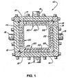
- an improved continuous casting mold 10 that is constructed according to a preferred embodiment of the invention includes four outer walls or water jackets 12 that each have a lower plenum 14 defined therein. As may be seen in FIGURES 1 and 2 , each of the outer walls or water jackets 12 further has a lower passage 16 defined therein, to communicate lower plenum 14 with a external coolant conduit, which in the preferred embodiment is a lower water pipe 18.
- each of the water jackets 12 further has an upper plenum 15 defined therein and further has an upper passage 17 for communicating the upper plenum 15 with a second external coolant conduit, which in the preferred embodiment is an upper water pipe 19, which is shown schematically in FIGURE 4 .
- Continuous casting mold 10 also includes four mold liners or "coppers" 20 each of which has a hot face or casting surface and is secured to an inner surface of a respective water jacket 12, as may best be seen in FIGURED 1.
- the hot faces or casting surfaces of the liner walls 20 together define a mold surface through which molten material such as steel may be passed and shaped, as is well known in this area of technology and is described in detail above.
- Each "copper” 20 or liner plate is preferably fabricated from a material that has high thermal connectivity, preferably copper, as is also well known in this technical area.
- each liner wall 20 has a number of slots 22 defined in an inner surface thereof which, together with the respective water jacket 12, defines a number of the passages 26, shown in FIGURE 2 , for transporting coolant such as water to cool the liner 20 during operation of the mold 10.
- each of the passages or water slots 26 is oriented so as to be substantially vertical, having an upper end that is located near an upper end 28 of the water jacket 12 and a lower end that is located near a lower end 30 of the water jacket 12.
- a first velocity plate 32 is positioned between the lower plenum 14 and the lower end of the passage 26, as is shown in FIGURE 2 , and similarly a second velocity plate is likewise positioned between the upper plenum 15 and the upper end of the passage 26.
- FIGURE 2 depicts a mold liner or copper 20 that is substantially new and that exhibits an original thickness To between the innermost extent 36 of passage 26, which is also known as the slot bottom, and the hotface or casting surface 38. At this thickness, it may be desirable to provide enhanced cooling to the meniscus region 34 of the casting surface 38. Accordingly, one important advantage that is provided by the invention is the step of making the determination that it is so desirable to direct the coolant from top to bottom and then initially introducing the coolant into the upper portion of the passage 26 in a direction toward the lower portion of the passage 26 so that the coolant that contacts the slot bottom 36 in the area of the slot bottom 36 that is close to the meniscus region 34 will have been preheated as little as possible.
- FIGURE 3 depicts a mold liner or copper 20 that through wear and the machining that is performed during reconditioning has become much thinner than it was originally.
- the mold liner or copper 20 shown in FIGURE 3 exhibits a thickness T c between the slot bottom 36 and the new casting surface 40 that represents an erosion of thickness with respect to the original size of the mold liner that is of a value T R .
- casting with a mold liner 20 that is new will be performed with the coolant being directed from top to bottom within the coolant passage 26.
- a new determination will be made whether the coolant should be directed from top to bottom or from bottom to top.
- the determination is made based on the remaining thickness T c of the mold liner between the slot bottom 36 and the casting surface 38.
- the specific value of T c at which the decision will be made to reverse the coolant flow will be made based on a number of factors. For example, the determination of T c could be based in part or in whole on measured temperatures during casting.
- the determination may also be based in whole or in part on the desired casting speed, on the composition of the material from which the mold liner 20 is fabricated, or on various surface treatments that may have been applied to the casting surface 38. Alternatively, the determination could be made based simply on an anticipated midpoint of the life of the mold liner 20.
- the value of T c at which the decision to reverse the coolant flow will depend most heavily on the type of mold that is being used (i.e. whether the mold is a conventional slab mold or a high speed funnel mold), and on the composition of the mold liner (i.e. whether the mold liner is fabricated from silver-bearing copper or chromium-zirconium copper, the details of both being well known in the industry).
- the preferred apparatus for permitting the coolant to be directed selectively from either top to bottom or bottom to top within the water jacket includes a simple valve arrangement 44 that is preferably positioned in the water piping beneath the continuous casting mold.
- a water supply pipe 40 supplies pressurized water or other coolant to the continuous casting mold, while a water return line 42 provides a return path for water that has been circulated through the continuous casting mold.
- Supply pipe 40 and return line 42 are preferably, and as is common throughout the industry, part of a continuous circulation system that includes a filtration area and an external cooling area that typically includes a heat exchanger and cooling tower for transferring the waste heat to the environment.
- valve arrangement 44 is configured in a situation such as that which is shown in FIGURE 2 wherein the water supply pipe 40 is communicated with the upper water pipe 19, which provides a path into the upper plenum 15 into the upper passage 17, as is shown in FIGURE 2 .
- the coolant water flows downwardly through the passage 26, as is shown in FIGURE 2 , into the lower plenum 14 and out through the lower passage 16 and into the lower water pipe 18 where it is communicated with return line 42.
- supply pipe 40 is instead communicated by the valve arrangement 44 with the lower water pipe 18, forcing the cooling water into the lower passage 16, through the lower plenum 14 and upwardly through the passage 26, wherein the coolant is preheated before it reaches the portion of the slot bottom 36 that is close to the meniscus region 34. Accordingly, the cooling effect is slightly mitigated, which is beneficial because of the thin condition of the mold liner 20.
- the coolant continues upwardly into the upper plenum 15, outwardly through the upper passage 17 and into the upper water pipe 19, which is communicated by the valve arrangement 44 with the return line 42.
Landscapes
- Engineering & Computer Science (AREA)
- Mechanical Engineering (AREA)
- Continuous Casting (AREA)
- Separation By Low-Temperature Treatments (AREA)
- Molds, Cores, And Manufacturing Methods Thereof (AREA)
- Moulds For Moulding Plastics Or The Like (AREA)
Claims (14)
- Procédé d'exploitation d'un moule de coulée continue (10) du type comprenant au moins un conduit de fluide de refroidissement (26) comprenant une fente (22) ayant une extrémité supérieure (28) et une extrémité inférieure (30), la fente (22) étant définie dans une chemise de moule (20) pour canaliser un fluide de refroidissement pendant la coulée, comprenant les étapes consistant à :(a) conduire une opération de coulée tout en forçant un fluide de refroidissement à passer dans ledit conduit de fluide de refroidissement (26) dans une première direction ; et(b) conduire une opération de coulée suivante tout en forçant un fluide de refroidissement à passer dans ledit conduit de fluide de refroidissement (26) dans une deuxième direction qui est opposée à la première direction,caractérisé en ce que l'étape (b) est exécutée dans l'opération de coulée qui suit immédiatement seulement dans le cas où l'épaisseur de la chemise de moule (20) qui reste entre l'extrémité inférieure (30) de la fente (22) et la surface de coulée (40) est inférieure à une épaisseur minimale prédéterminée (TC).
- Procédé selon la revendication 1, dans lequel la chemise de moule (20) est reconditionnée entre le passage du fluide de refroidissement dans le conduit (26) dans la première direction et son passage dans la deuxième direction.
- Procédé selon la revendication 2, dans lequel l'étape de reconditionnement de la chemise de moule (20) comprend le fait de retirer une quantité de matière d'une surface de coulée (38) de la chemise de moule afin de reconditionner la surface de coulée (38) puis de déterminer l'épaisseur (TC) de la chemise de moule (20) qui reste entre le fond de la fente (36) et la surface de coulée (38).
- Procédé selon la revendication 1, dans lequel le moule de coulée continue (10) est un moule en entonnoir, et dans lequel une épaisseur minimale prédéterminée (TC) est comprise dans un intervalle d'environ 0,99 cm à environ 2,21 cm.
- Procédé selon la revendication 4, dans lequel ledit moule (10) comprend une chemise de moule (20) qui est fabriquée à partir d'un matériau comprenant un alliage de cuivre argentifère, et dans lequel l'épaisseur minimale prédéterminée est comprise dans un intervalle d'environ 1,19 cm à environ 2,21 cm.
- Procédé selon la revendication 5, dans lequel ladite épaisseur minimale prédéterminée est comprise dans un intervalle d'environ 1,40 cm à environ 2,01 cm.
- Procédé selon la revendication 4, dans lequel ledit moule (10) comprend une chemise de moule (20) qui est fabriquée à partir d'un matériau comprenant un alliage de cuivre au chrome-zirconium, et dans lequel l'épaisseur minimale prédéterminée est comprise dans un intervalle d'environ 0,99 cm à environ 1,90 cm.
- Procédé selon la revendication 7, dans lequel ladite épaisseur minimale prédéterminée est comprise dans un intervalle d'environ 1,19 cm à environ 1,70 cm.
- Procédé selon la revendication 1, dans lequel ledit moule de coulée continue (10) est une lingotière à brame conventionnelle, et dans lequel ladite épaisseur minimale prédéterminée est comprise dans un intervalle d'environ 0,46 cm à environ 3,00 cm.
- Procédé selon la revendication 9, dans lequel ledit moule (10) comprend une chemise de moule (20) qui est fabriquée à partir d'un matériau comprenant un alliage de cuivre argentifère, et dans lequel l'épaisseur minimale prédéterminée est comprise dans un intervalle d'environ 0,51 cm à environ 3,00 cm.
- Procédé selon la revendication 10, dans lequel ladite épaisseur minimale prédéterminée est comprise dans un intervalle d'environ 0,76 cm à environ 2,69 cm.
- Procédé selon la revendication 8, dans lequel ledit moule (10) comprend une chemise de moule (20) qui est fabriquée à partir d'un matériau comprenant un alliage de cuivre au chrome-zirconium, et dans lequel l'épaisseur minimale prédéterminée est comprise dans un intervalle d'environ 0,46 cm à environ 2,59 cm.
- Procédé selon la revendication 12, dans lequel ladite épaisseur minimale prédéterminée est comprise dans un intervalle d'environ 0,71 cm à environ 2,31 cm.
- Procédé selon l'une quelconque des revendications précédentes, dans lequel ladite épaisseur est mesurée dans une région qui est proche d'un endroit de ménisque prévu.
Applications Claiming Priority (3)
| Application Number | Priority Date | Filing Date | Title |
|---|---|---|---|
| US658997 | 2000-09-11 | ||
| US09/658,997 US6374903B1 (en) | 2000-09-11 | 2000-09-11 | System and process for optimizing cooling in continuous casting mold |
| PCT/US2001/028381 WO2002022293A1 (fr) | 2000-09-11 | 2001-09-12 | Systeme et procede d'optimisation du refroidissement dans un moule de coulee continue |
Publications (3)
| Publication Number | Publication Date |
|---|---|
| EP1345720A1 EP1345720A1 (fr) | 2003-09-24 |
| EP1345720A4 EP1345720A4 (fr) | 2006-03-22 |
| EP1345720B1 true EP1345720B1 (fr) | 2008-08-27 |
Family
ID=24643611
Family Applications (1)
| Application Number | Title | Priority Date | Filing Date |
|---|---|---|---|
| EP01970798A Expired - Lifetime EP1345720B1 (fr) | 2000-09-11 | 2001-09-12 | Procede d'optimisation du refroidissement dans un moule de coulee continue |
Country Status (13)
| Country | Link |
|---|---|
| US (1) | US6374903B1 (fr) |
| EP (1) | EP1345720B1 (fr) |
| CN (1) | CN1262371C (fr) |
| AT (1) | ATE406228T1 (fr) |
| AU (1) | AU2001290765A1 (fr) |
| CA (1) | CA2425130C (fr) |
| DE (1) | DE60135578D1 (fr) |
| ES (1) | ES2311543T3 (fr) |
| RU (1) | RU2259256C2 (fr) |
| TW (1) | TW592848B (fr) |
| UA (1) | UA76727C2 (fr) |
| WO (1) | WO2002022293A1 (fr) |
| ZA (1) | ZA200302782B (fr) |
Families Citing this family (8)
| Publication number | Priority date | Publication date | Assignee | Title |
|---|---|---|---|---|
| US20040256080A1 (en) * | 2001-10-18 | 2004-12-23 | Werner Rahmfeld | Method and device for optimizing the cooling capacity of a continuous casting mold for liquid metals, particularly for liquid steel |
| UA79025C2 (uk) * | 2002-11-13 | 2007-05-10 | Смс Демаг Акцієнгезелльшафт | Кристалізатор для безперервного розливу рідких металів, зокрема сталей, при високій швидкості розливу для одержання полігональних сортових, чорнових і призначених для прокату на блюмінгу заготовок |
| EP1468760B1 (fr) * | 2003-04-16 | 2005-05-25 | Concast Ag | Lingotière tubalaire pour la coulée continue |
| US20060191661A1 (en) * | 2003-10-01 | 2006-08-31 | Zajber Adolf G | Continuous casting mold for casting molten metals, particularly steel materials, at high casting rates to form polygonal billet, bloom, and preliminary section castings and the like |
| US8313321B2 (en) * | 2009-06-05 | 2012-11-20 | Ness Inventions Inc. | Mold assembly employing fluid heating |
| US20120103555A1 (en) * | 2010-11-01 | 2012-05-03 | Sears Jr James B | Ultra-thin slab or thick-strip casting |
| CN118385501B (zh) * | 2024-05-09 | 2024-09-20 | 临沂兴大铸业有限公司 | 一种铸造设备温度控制装置 |
| CN120772479B (zh) * | 2025-09-02 | 2025-12-23 | 靖江新舟合金材料有限公司 | 铝合金半连续铸造装置 |
Family Cites Families (22)
| Publication number | Priority date | Publication date | Assignee | Title |
|---|---|---|---|---|
| US2169893A (en) | 1937-11-01 | 1939-08-15 | Chase Brass & Copper Co | Cooling means for continuous casting apparatus |
| US2893080A (en) | 1954-03-26 | 1959-07-07 | Norman P Goss | Apparatus for the continuous casting of metals |
| US2862265A (en) | 1956-12-10 | 1958-12-02 | Aluminum Co Of America | Continuous casting mold |
| CH424102A (de) | 1965-05-03 | 1966-11-15 | Wertli Alfred | Verfahren zum Stranggiessen eines Bandes und Kühlvorrichtung zum Durchführen des Verfahrens |
| US3528487A (en) | 1967-06-05 | 1970-09-15 | Interlake Steel Corp | Continuous casting machine |
| US3763920A (en) | 1972-03-16 | 1973-10-09 | United States Steel Corp | Water inlet construction for continuous-casting molds |
| FR2248103B1 (fr) * | 1973-10-19 | 1978-02-17 | Siderurgie Fse Inst Rech | |
| US3978910A (en) | 1975-07-07 | 1976-09-07 | Gladwin Floyd R | Mold plate cooling system |
| US4182397A (en) | 1978-07-03 | 1980-01-08 | Allis-Chalmers Corporation | Continuous casting mold and means for securing mold liners therein |
| SU952422A1 (ru) | 1980-12-22 | 1982-08-23 | Могилевское Отделение Физико-Технического Института Ан Бсср | Кристаллизатор |
| US4535832A (en) | 1981-04-29 | 1985-08-20 | Gus Sevastakis | Continuous casting apparatus |
| US4640337A (en) | 1985-05-01 | 1987-02-03 | Gus Sevastakis | Continuous casting apparatus |
| IT1215386B (it) * | 1987-03-18 | 1990-02-08 | Danieli Off Mecc | Procedimento di recupero per cristallizzatore di lingottiera per colata continua. |
| AT389251B (de) | 1987-12-23 | 1989-11-10 | Voest Alpine Ind Anlagen | Kuehlung einer stranggiesskokille |
| SU1708504A1 (ru) * | 1989-05-10 | 1992-01-30 | Государственный научно-исследовательский, проектный и конструкторский институт сплавов и обработки цветных металлов "Гипроцветметобработка" | Система охлаждени графитового кристаллизатора дл непрерывного лить полосовой заготовки из цветных сплавов |
| DE4117052A1 (de) | 1990-07-23 | 1992-11-26 | Mannesmann Ag | Fluessigkeitsgekuehlte kokille fuer das stranggiessen von metallen |
| US5207266A (en) | 1992-01-03 | 1993-05-04 | Chuetsu Metal Works Co., Ltd. | Water-cooled copper casting mold |
| ES2148374T3 (es) * | 1994-06-06 | 2000-10-16 | Danieli Off Mecc | Metodo para controlar las deformaciones de las paredes laterales de un cristalizador, y cristalizador de colada continua. |
| DE69518360T2 (de) * | 1994-06-06 | 2000-12-28 | Danieli & C. Officine Meccaniche S.P.A., Buttrio | Stranggiesskokille mit verbessertem Wärmeaustausch sowie Verfahren zur Erhöhung des Wärmeaustauschs einer Stranggiesskokille |
| FR2723014B1 (fr) * | 1994-07-29 | 1996-09-20 | Pechiney Rhenalu | Procede et dispositif de correction de l'ovalisation de cylindres de coulee continue de bande metallique |
| US5526869A (en) * | 1994-09-29 | 1996-06-18 | Gladwin Corporation | Mold for continuous casting system |
| US5771958A (en) * | 1995-09-14 | 1998-06-30 | Ag Industries, Inc. | Mold for continuous casting system |
-
2000
- 2000-09-11 US US09/658,997 patent/US6374903B1/en not_active Expired - Fee Related
-
2001
- 2001-09-12 ES ES01970798T patent/ES2311543T3/es not_active Expired - Lifetime
- 2001-09-12 AT AT01970798T patent/ATE406228T1/de active
- 2001-09-12 DE DE60135578T patent/DE60135578D1/de not_active Expired - Lifetime
- 2001-09-12 CA CA002425130A patent/CA2425130C/fr not_active Expired - Fee Related
- 2001-09-12 EP EP01970798A patent/EP1345720B1/fr not_active Expired - Lifetime
- 2001-09-12 CN CNB018183468A patent/CN1262371C/zh not_active Expired - Fee Related
- 2001-09-12 AU AU2001290765A patent/AU2001290765A1/en not_active Abandoned
- 2001-09-12 WO PCT/US2001/028381 patent/WO2002022293A1/fr not_active Ceased
- 2001-09-12 RU RU2003110322/02A patent/RU2259256C2/ru not_active IP Right Cessation
- 2001-12-09 UA UA2003043143A patent/UA76727C2/uk unknown
-
2003
- 2003-04-09 ZA ZA200302782A patent/ZA200302782B/en unknown
- 2003-04-18 TW TW092109145A patent/TW592848B/zh not_active IP Right Cessation
Also Published As
| Publication number | Publication date |
|---|---|
| CA2425130A1 (fr) | 2002-03-21 |
| TW200422120A (en) | 2004-11-01 |
| CN1473080A (zh) | 2004-02-04 |
| EP1345720A1 (fr) | 2003-09-24 |
| RU2259256C2 (ru) | 2005-08-27 |
| AU2001290765A1 (en) | 2002-03-26 |
| ES2311543T3 (es) | 2009-02-16 |
| ZA200302782B (en) | 2004-08-16 |
| ATE406228T1 (de) | 2008-09-15 |
| TW592848B (en) | 2004-06-21 |
| CN1262371C (zh) | 2006-07-05 |
| WO2002022293A1 (fr) | 2002-03-21 |
| US6374903B1 (en) | 2002-04-23 |
| EP1345720A4 (fr) | 2006-03-22 |
| UA76727C2 (uk) | 2006-09-15 |
| DE60135578D1 (de) | 2008-10-09 |
| CA2425130C (fr) | 2006-10-10 |
Similar Documents
| Publication | Publication Date | Title |
|---|---|---|
| EP1345720B1 (fr) | Procede d'optimisation du refroidissement dans un moule de coulee continue | |
| US5871040A (en) | Process for continuously casting thin slabs | |
| US6367539B1 (en) | Crystalliser for continuous casting | |
| US5927378A (en) | Continuous casting mold and method | |
| US5611390A (en) | Continuous-casting crystalliser with increased heat exchange and method to increase the heat exchange in a continuous-casting crystalliser | |
| US3587718A (en) | Continuous casting apparatus | |
| EP1140392B1 (fr) | Dispositif et procede de coulee continue a grande vitesse | |
| JP7151665B2 (ja) | 連続鋳造用水冷鋳型及び鋼の連続鋳造方法 | |
| EP0686446B1 (fr) | Cristallisoir de coulée continue ayant un échange de chaleur amélioré et procédé pour augmenter l'échange de chaleur d'un cristallisoir de coulée continue | |
| JP6947192B2 (ja) | 鋼の連続鋳造用鋳型及び鋼の連続鋳造方法 | |
| US4911226A (en) | Method and apparatus for continuously casting strip steel | |
| EP2054178B1 (fr) | Cristallisoir | |
| US6474401B1 (en) | Continuous casting mold | |
| US20190210099A1 (en) | Method for continuous casting of two or more long products using a single continuous casting strand | |
| JPS609553A (ja) | 絞り込み式連続鋳造機 | |
| JPH05293597A (ja) | 中空丸鋳片用の連続鋳造鋳型 | |
| CN119035524B (zh) | 一种控制热轧板卷边部线性缺陷的板坯加工方法 | |
| EP0780176A2 (fr) | Dispositif et procédé pour la coulée continue | |
| RU2800555C1 (ru) | Кристаллизатор непрерывной отливки металлического изделия и соответствующий способ отливки | |
| CN120715177A (zh) | 方坯结晶器及其操作方法 | |
| US20030010471A1 (en) | Continuous casting mold and method | |
| DR Thornton BSc | Moulds for Continuous Casting | |
| JPH04220140A (ja) | 丸ビレットまたはビームブランクの連続鋳造方法及びその連鋳鋳型 |
Legal Events
| Date | Code | Title | Description |
|---|---|---|---|
| PUAI | Public reference made under article 153(3) epc to a published international application that has entered the european phase |
Free format text: ORIGINAL CODE: 0009012 |
|
| 17P | Request for examination filed |
Effective date: 20030408 |
|
| AK | Designated contracting states |
Kind code of ref document: A1 Designated state(s): AT BE CH CY DE DK ES FI FR GB GR IE IT LI LU MC NL PT SE TR |
|
| AX | Request for extension of the european patent |
Extension state: AL LT LV MK RO SI |
|
| RBV | Designated contracting states (corrected) |
Designated state(s): AT BE CH CY DE ES GB IT LI |
|
| A4 | Supplementary search report drawn up and despatched |
Effective date: 20060206 |
|
| RTI1 | Title (correction) |
Free format text: PROCESS FOR OPTIMIZING COOLING IN CONTINUOUS CASTING MOLD |
|
| GRAP | Despatch of communication of intention to grant a patent |
Free format text: ORIGINAL CODE: EPIDOSNIGR1 |
|
| GRAS | Grant fee paid |
Free format text: ORIGINAL CODE: EPIDOSNIGR3 |
|
| GRAA | (expected) grant |
Free format text: ORIGINAL CODE: 0009210 |
|
| AK | Designated contracting states |
Kind code of ref document: B1 Designated state(s): AT DE ES GB IT |
|
| REG | Reference to a national code |
Ref country code: GB Ref legal event code: FG4D |
|
| REF | Corresponds to: |
Ref document number: 60135578 Country of ref document: DE Date of ref document: 20081009 Kind code of ref document: P |
|
| REG | Reference to a national code |
Ref country code: ES Ref legal event code: FG2A Ref document number: 2311543 Country of ref document: ES Kind code of ref document: T3 |
|
| PLBE | No opposition filed within time limit |
Free format text: ORIGINAL CODE: 0009261 |
|
| STAA | Information on the status of an ep patent application or granted ep patent |
Free format text: STATUS: NO OPPOSITION FILED WITHIN TIME LIMIT |
|
| 26N | No opposition filed |
Effective date: 20090528 |
|
| PG25 | Lapsed in a contracting state [announced via postgrant information from national office to epo] |
Ref country code: IT Free format text: LAPSE BECAUSE OF NON-PAYMENT OF DUE FEES Effective date: 20080912 |
|
| PGRI | Patent reinstated in contracting state [announced from national office to epo] |
Ref country code: IT Effective date: 20110616 |
|
| PGFP | Annual fee paid to national office [announced via postgrant information from national office to epo] |
Ref country code: GB Payment date: 20120912 Year of fee payment: 12 |
|
| PGFP | Annual fee paid to national office [announced via postgrant information from national office to epo] |
Ref country code: DE Payment date: 20120928 Year of fee payment: 12 Ref country code: ES Payment date: 20120903 Year of fee payment: 12 Ref country code: IT Payment date: 20120925 Year of fee payment: 12 |
|
| PGFP | Annual fee paid to national office [announced via postgrant information from national office to epo] |
Ref country code: AT Payment date: 20120927 Year of fee payment: 12 |
|
| REG | Reference to a national code |
Ref country code: AT Ref legal event code: MM01 Ref document number: 406228 Country of ref document: AT Kind code of ref document: T Effective date: 20130912 |
|
| GBPC | Gb: european patent ceased through non-payment of renewal fee |
Effective date: 20130912 |
|
| REG | Reference to a national code |
Ref country code: DE Ref legal event code: R119 Ref document number: 60135578 Country of ref document: DE Effective date: 20140401 |
|
| PG25 | Lapsed in a contracting state [announced via postgrant information from national office to epo] |
Ref country code: GB Free format text: LAPSE BECAUSE OF NON-PAYMENT OF DUE FEES Effective date: 20130912 |
|
| PG25 | Lapsed in a contracting state [announced via postgrant information from national office to epo] |
Ref country code: AT Free format text: LAPSE BECAUSE OF NON-PAYMENT OF DUE FEES Effective date: 20130912 Ref country code: IT Free format text: LAPSE BECAUSE OF NON-PAYMENT OF DUE FEES Effective date: 20130912 Ref country code: DE Free format text: LAPSE BECAUSE OF NON-PAYMENT OF DUE FEES Effective date: 20140401 |
|
| REG | Reference to a national code |
Ref country code: ES Ref legal event code: FD2A Effective date: 20141008 |
|
| PG25 | Lapsed in a contracting state [announced via postgrant information from national office to epo] |
Ref country code: ES Free format text: LAPSE BECAUSE OF NON-PAYMENT OF DUE FEES Effective date: 20130913 |