EP1346385B1 - Automatischer strombegrenzender schutzschalter - Google Patents
Automatischer strombegrenzender schutzschalter Download PDFInfo
- Publication number
- EP1346385B1 EP1346385B1 EP01272646A EP01272646A EP1346385B1 EP 1346385 B1 EP1346385 B1 EP 1346385B1 EP 01272646 A EP01272646 A EP 01272646A EP 01272646 A EP01272646 A EP 01272646A EP 1346385 B1 EP1346385 B1 EP 1346385B1
- Authority
- EP
- European Patent Office
- Prior art keywords
- contact
- movable contact
- circuit breaker
- current limiting
- fixed
- Prior art date
- Legal status (The legal status is an assumption and is not a legal conclusion. Google has not performed a legal analysis and makes no representation as to the accuracy of the status listed.)
- Expired - Lifetime
Links
Images


Classifications
-
- H—ELECTRICITY
- H01—ELECTRIC ELEMENTS
- H01H—ELECTRIC SWITCHES; RELAYS; SELECTORS; EMERGENCY PROTECTIVE DEVICES
- H01H73/00—Protective overload circuit-breaking switches in which excess current opens the contacts by automatic release of mechanical energy stored by previous operation of a hand reset mechanism
- H01H73/02—Details
- H01H73/04—Contacts
- H01H73/045—Bridging contacts
-
- H—ELECTRICITY
- H01—ELECTRIC ELEMENTS
- H01H—ELECTRIC SWITCHES; RELAYS; SELECTORS; EMERGENCY PROTECTIVE DEVICES
- H01H1/00—Contacts
- H01H1/12—Contacts characterised by the manner in which co-operating contacts engage
- H01H1/14—Contacts characterised by the manner in which co-operating contacts engage by abutting
- H01H1/20—Bridging contacts
- H01H2001/2091—Bridging contacts having two pivotally and electrically connected halve bridges
-
- H—ELECTRICITY
- H01—ELECTRIC ELEMENTS
- H01H—ELECTRIC SWITCHES; RELAYS; SELECTORS; EMERGENCY PROTECTIVE DEVICES
- H01H77/00—Protective overload circuit-breaking switches operated by excess current and requiring separate action for resetting
- H01H77/02—Protective overload circuit-breaking switches operated by excess current and requiring separate action for resetting in which the excess current itself provides the energy for opening the contacts, and having a separate reset mechanism
- H01H77/10—Protective overload circuit-breaking switches operated by excess current and requiring separate action for resetting in which the excess current itself provides the energy for opening the contacts, and having a separate reset mechanism with electrodynamic opening
- H01H77/102—Protective overload circuit-breaking switches operated by excess current and requiring separate action for resetting in which the excess current itself provides the energy for opening the contacts, and having a separate reset mechanism with electrodynamic opening characterised by special mounting of contact arm, allowing blow-off movement
- H01H77/104—Protective overload circuit-breaking switches operated by excess current and requiring separate action for resetting in which the excess current itself provides the energy for opening the contacts, and having a separate reset mechanism with electrodynamic opening characterised by special mounting of contact arm, allowing blow-off movement with a stable blow-off position
Definitions
- the present invention relates to a circuit breaker and particularly to an automatic current limiting circuit breaker that has a system with double interruption in series with at least two arc quenching chambers for each pole.
- Low-voltage electrical systems characterized by high currents and power levels normally use specific devices provided with a system that ensures the nominal current required for the various users, the insertion and disconnection of the load, the protection of the loads against abnormal events such as overloading and short-circuits by automatically opening the circuit, and finally the disconnection of the protected circuit by opening the movable contacts with respect to the fixed contacts in order to achieve full isolation of the load with respect to the electric power source.
- These devices are commonly known as automatic power switches for use in low-voltage industrial systems.
- each pole is interrupted in two separate regions that are electrically in series to each other, so that each one is subjected to less mechanical and thermal stress.
- the second solution is based on a reduction of the tripping time, so as to prevent the presumed short-circuit current from reaching its maximum value.
- the aim of the present invention is to provide an automatic current limiting circuit breaker whose mechanism and operating principle are simplified with respect to the circuit breakers of the known art.
- Document FR 2 373 143 discloses a device according to the preamble of claim 1.
- an object of the present invention is to provide an automatic current limiting circuit breaker that improves the distribution of the mechanical loads supported by the movable contacts.
- Another object is to provide an automatic current limiting circuit breaker in which energy dissipation due to the Joule effect is minimized.
- Another object is to provide an automatic current limiting circuit breaker that has reduced overall dimensions for an equal electrical performance and expected life.
- Another object of the present invention is to provide an automatic current limiting circuit breaker that is highly reliable, relatively easy to provide and at competitive costs.
- an automatic current limiting circuit breaker which comprises an insulating enclosure that accommodates fixed contact means and movable contact means, actuation means for actuating said movable contact means between open-circuit conditions and closed-circuit conditions, and arc quenching means that comprise at least one first and one second arc quenching chamber which are mutually separate
- the fixed contact means comprising at least one first and one second fixed contact, which are mutually spaced and positioned respectively adjacent to the first and second arc quenching chambers
- the movable contact means comprising at least one first movable contact and one second movable contact, which are electrically series-connected and can move simultaneously between open-circuit and closed-circuit positions
- the movable contact means comprise a first contact arm and a second contact arm that have a first end at which the first movable contact and the second movable contact are respectively fixed and a second end that is fixed on, and free to rotate about, a common pivot that
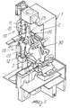
- the automatic current limiting circuit breaker comprises an insulating enclosure 1, of which only a cutout view is shown.
- the enclosure 1 accommodates fixed contact means, generally designated by the reference numeral 10, and movable contact means, generally designated by the reference numeral 20.
- the circuit breaker also comprises actuation means for moving the movable contact means between an open-circuit condition (shown in dashed lines in Figures 3 and 4) and a closed-circuit condition.
- a detail of the actuation means is given in Figures 1 and 4, which show an example of kinematic actuation chain 30.
- the circuit breaker further comprises arc quenching means, constituted by two mutually separate arc quenching chambers; the arc quenching chambers are not shown in the figures for the sake of clarity.
- Figure 1 shows the seats 2 and 3 formed in the enclosure 1 and suitable to accommodate said arc quenching chambers.
- the fixed contact means 10 comprise a first fixed contact 11 and a second fixed contact 12, which are mutually spaced and arranged respectively adjacent to the first and second arc quenching chambers, at the seats 2 and 3.
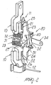
- the movable contact means 20 comprise a first movable contact 21 and a second movable contact 22, which are electrically series-connected and can be moved simultaneously between open-circuit and closed-circuit positions.
- the movable contact means 20 furthermore comprise a first contact arm 23 and a second contact arm 24, which are constituted by two elongated conducting plates that have a first end, designated by the reference numerals 25 and 26 respectively, at which the first movable contact 21 and the second movable contact 22 are fixed.
- the second end which is designated by the reference numeral 27 for the first movable arm 23, whereas the end of the second movable arm 24 is not visible, is fixed to a common pivot 40 so that the two movable arms 23 and 24 are free to rotate about it.
- the common pivot 40 is therefore operatively connected to the actuation means in order to allow the movement of the movable contacts.
- the first and second contact arms 23 and 24 are mutually electrically series-connected by virtue of at least one flexible conductor.
- the electrical series connection can be provided by means of a pair of copper braids 51 and 52.
- the common pivot 40 is fixed to a plate 31 that is operatively connected to the actuation means.
- the plate 31 can slide freely in an appropriate space formed between the seats 2 and 3 of the arc quenching chambers.
- the first and second contact arms 23 and 24 are preferably operatively associated with elastic means that perform this function.
- the elastic means can be constituted for example by two springs 32 and 33 that are respectively associated with the first and second contact arms 23 and 24, for example proximate to their end that lies opposite the movable contact 20.
- connection of the movable contact parts to the actuation means can be performed for example by means of a coupling lever 34, one end of which is rigidly coupled to the pivot 40 while the other end is rigidly coupled to the kinematic chain 30.
- the reduced complexity of the kinematic system allows to reduce the overall space occupation of the units for an equal electrical performance and expected life.
Landscapes
- Breakers (AREA)
- Control Of Eletrric Generators (AREA)
- Ignition Installations For Internal Combustion Engines (AREA)
- Remote Monitoring And Control Of Power-Distribution Networks (AREA)
- Arc-Extinguishing Devices That Are Switches (AREA)
Claims (6)
- Automatischer strombegrenzender Trennschalter, der ein isolierendes Gehäuse (1) aufweist, in dem Festkontaktmittel (10) und Laufkontaktmittel (20), Stellmittel zur Verstellung der Laufkontaktmittel (20) zwischen offenen und geschlossenen Schaltkreisbedingungen und Lichtbogenlöschmittel untergebracht sind, die mindestens eine erste und eine zweite Lichtbogenlöschkammer einschließen, die voneinander getrennt sind, wobei die Festkontaktmittel (10) mindestens einen ersten (11) und einen zweiten Festkontakt (12) einschließen, die voneinander beabstandet und jeweils angrenzend an die ersten bzw. zweiten Lichtbogenlöschkammern angeordnet sind, wobei die Laufkontaktmittel (20) mindestens einen ersten (21) Laufkontakt und einen zweiten Lautkontakt (22) einschließen, die elektrisch in Reihe geschaltet sind und sich gleichzeitig zwischen offenen und geschlossenen Schaltkreispositionen bewegen können, wodurch die Lautkontaktmittel (20) einen ersten Kontaktarm (23) und einen zweiten Kontaktarm (24) aufweisen, die ein erstes Ende (25, 26), an dem der erste Laufkontakt (21) bzw. der zweite Laufkontakt (22) befestigt sind, und ein zweites Ende (27) aufweisen, das an einem gemeinsamen Drehzapfen (40), der wirkmäßig mit dem Stellmittel (30) verbunden ist, befestigt ist und sich frei um diesen drehen kann, dadurch gekennzeichnet, dass der erste Kontaktarm (23) wirkmäßig mit einem ersten elastischen Mittel (32) verbunden ist und der zweite Kontaktarm (24) wirkmäßig mit einem zweiten elastischen Mittel (33) verbunden ist.
- Automatischer strombegrenzender Trennschalter nach Anspruch 1, dadurch gekennzeichnet, dass die ersten und zweiten Kontaktarme (23, 24) wirkmäßig mit den ersten und zweiten elastischen Mitteln (23, 24) nahe an einem Ende, das sich gegenüber dem entsprechenden Laufkontakt (21, 22) befindet, verbunden sind.
- Automatischer strombegrenzender Trennschalter nach Anspruch 1 oder 2, dadurch gekennzeichnet, dass die ersten und zweiten Kontaktarme (23, 24) mittels mindestens eines flexiblen Leiters elektrisch in Reihe geschaltet sind.
- Automatischer strombegrenzender Trennschalter nach Anspruch 3, dadurch gekennzeichnet, dass die ersten und zweiten Kontaktarme (23, 24) mittels eines Paars aus Kupferlitzen (51, 52) elektrisch in Reihe geschaltet sind.
- Automatischer strombegrenzender Trennschalter nach einem oder mehreren der vorangehenden Ansprüche, dadurch gekennzeichnet, dass der gemeinsame Drehzapfen (40) an einer Platte (31) befestigt ist, die wirkmäßig mit dem Stellmittel verbunden ist.
- Automatischer strombegrenzender Trennschalter nach einem oder mehreren der vorangehenden Ansprüche, dadurch gekennzeichnet, dass das Stellmittel einen Antriebsstrang (30) und einen Verbindungshebel (34) aufweist.
Applications Claiming Priority (3)
| Application Number | Priority Date | Filing Date | Title |
|---|---|---|---|
| ITMI20002875 | 2000-12-29 | ||
| IT2000MI002875A IT1319707B1 (it) | 2000-12-29 | 2000-12-29 | Interruttore automatico limitatore di corrente |
| PCT/EP2001/014850 WO2002054431A1 (en) | 2000-12-29 | 2001-12-12 | Automatic current limiting circuit breaker |
Publications (2)
| Publication Number | Publication Date |
|---|---|
| EP1346385A1 EP1346385A1 (de) | 2003-09-24 |
| EP1346385B1 true EP1346385B1 (de) | 2007-06-20 |
Family
ID=11446371
Family Applications (1)
| Application Number | Title | Priority Date | Filing Date |
|---|---|---|---|
| EP01272646A Expired - Lifetime EP1346385B1 (de) | 2000-12-29 | 2001-12-12 | Automatischer strombegrenzender schutzschalter |
Country Status (7)
| Country | Link |
|---|---|
| EP (1) | EP1346385B1 (de) |
| CN (1) | CN1484846A (de) |
| AT (1) | ATE365373T1 (de) |
| DE (1) | DE60129041T2 (de) |
| ES (1) | ES2287075T3 (de) |
| IT (1) | IT1319707B1 (de) |
| WO (1) | WO2002054431A1 (de) |
Families Citing this family (2)
| Publication number | Priority date | Publication date | Assignee | Title |
|---|---|---|---|---|
| DE102011008831A1 (de) * | 2011-01-19 | 2012-07-19 | Abb Ag | Istallationsschaltgerät |
| CN102969210B (zh) * | 2011-08-31 | 2017-06-09 | 首瑞(北京)投资管理集团有限公司 | 断路器静触头 |
Family Cites Families (2)
| Publication number | Priority date | Publication date | Assignee | Title |
|---|---|---|---|---|
| IT1006446B (it) * | 1974-04-12 | 1976-09-30 | Sace Spa | Interruttore elettrico limitatore di corrente esente da rimbalzi in fase di apertura |
| FR2373143A1 (fr) * | 1976-12-06 | 1978-06-30 | Telemecanique Electrique | Contacteur limiteur a haut pouvoir de coupure |
-
2000
- 2000-12-29 IT IT2000MI002875A patent/IT1319707B1/it active
-
2001
- 2001-12-12 AT AT01272646T patent/ATE365373T1/de not_active IP Right Cessation
- 2001-12-12 CN CNA018215440A patent/CN1484846A/zh active Pending
- 2001-12-12 DE DE60129041T patent/DE60129041T2/de not_active Expired - Lifetime
- 2001-12-12 WO PCT/EP2001/014850 patent/WO2002054431A1/en not_active Ceased
- 2001-12-12 EP EP01272646A patent/EP1346385B1/de not_active Expired - Lifetime
- 2001-12-12 ES ES01272646T patent/ES2287075T3/es not_active Expired - Lifetime
Non-Patent Citations (1)
| Title |
|---|
| None * |
Also Published As
| Publication number | Publication date |
|---|---|
| CN1484846A (zh) | 2004-03-24 |
| ATE365373T1 (de) | 2007-07-15 |
| IT1319707B1 (it) | 2003-11-03 |
| DE60129041D1 (de) | 2007-08-02 |
| EP1346385A1 (de) | 2003-09-24 |
| ES2287075T3 (es) | 2007-12-16 |
| WO2002054431A1 (en) | 2002-07-11 |
| ITMI20002875A1 (it) | 2002-06-29 |
| DE60129041T2 (de) | 2008-02-21 |
Similar Documents
| Publication | Publication Date | Title |
|---|---|---|
| CA2623847C (en) | Electrical switching apparatus, and conductor assembly and shunt assembly therefor | |
| CA2271247C (en) | Electrical switching apparatus having arc runner integral with stationary arcing contact | |
| EP0955658A2 (de) | Ellektrischer Schaltgerät mit verbesserten Kontaktarmträgervorrichtung | |
| EP1442466B1 (de) | Niederspannungsleistungsschalter | |
| US6689979B1 (en) | Switching contact arrangement of a low voltage circuit breaker with main contacts, intermediate contact and arcing contacts | |
| EP0961306B1 (de) | Lastschalter mit modulärem Kontaktsystem für Rahmen mit unterschiedlichen Grössen | |
| US10748729B2 (en) | Low profile fusible disconnect switch device | |
| US9129768B2 (en) | Multipole electrical switching device | |
| US11804345B2 (en) | Low-voltage circuit breaker | |
| EP1346385B1 (de) | Automatischer strombegrenzender schutzschalter | |
| EP2290667B1 (de) | Bewegliche verschiebbare Schützanordnung für Schutzschalter | |
| KR20210084627A (ko) | 이중 브레이크 포인트 차단기의 가동접촉자 기구 | |
| CN111508784B (zh) | 具有灭弧功能的窄轮廓断路器 | |
| CN212392149U (zh) | 具有电动力补偿的分断单元和自动双电源转换开关 | |
| EP1218899B1 (de) | Elektrischer pol für einen niederspannungsschutzschalter | |
| CA1331998C (en) | Circuit breaker with low voltage contact structure | |
| EP4330998A1 (de) | Schlanker schutzschalter | |
| CN222775203U (zh) | 一种负荷隔离开关的分合闸机构 | |
| RU2795228C2 (ru) | Автоматический выключатель низкого напряжения | |
| RU10287U1 (ru) | Автоматический выключатель |
Legal Events
| Date | Code | Title | Description |
|---|---|---|---|
| PUAI | Public reference made under article 153(3) epc to a published international application that has entered the european phase |
Free format text: ORIGINAL CODE: 0009012 |
|
| 17P | Request for examination filed |
Effective date: 20030722 |
|
| AK | Designated contracting states |
Kind code of ref document: A1 Designated state(s): AT BE CH CY DE DK ES FI FR GB GR IE IT LI LU MC NL PT SE TR |
|
| AX | Request for extension of the european patent |
Extension state: AL LT LV MK RO SI |
|
| RAP1 | Party data changed (applicant data changed or rights of an application transferred) |
Owner name: ABB SERVICE S.R.L |
|
| GRAP | Despatch of communication of intention to grant a patent |
Free format text: ORIGINAL CODE: EPIDOSNIGR1 |
|
| GRAS | Grant fee paid |
Free format text: ORIGINAL CODE: EPIDOSNIGR3 |
|
| GRAA | (expected) grant |
Free format text: ORIGINAL CODE: 0009210 |
|
| AK | Designated contracting states |
Kind code of ref document: B1 Designated state(s): AT BE CH CY DE DK ES FI FR GB GR IE IT LI LU MC NL PT SE TR |
|
| PG25 | Lapsed in a contracting state [announced via postgrant information from national office to epo] |
Ref country code: LI Free format text: LAPSE BECAUSE OF FAILURE TO SUBMIT A TRANSLATION OF THE DESCRIPTION OR TO PAY THE FEE WITHIN THE PRESCRIBED TIME-LIMIT Effective date: 20070620 Ref country code: CH Free format text: LAPSE BECAUSE OF FAILURE TO SUBMIT A TRANSLATION OF THE DESCRIPTION OR TO PAY THE FEE WITHIN THE PRESCRIBED TIME-LIMIT Effective date: 20070620 |
|
| REG | Reference to a national code |
Ref country code: GB Ref legal event code: FG4D |
|
| REG | Reference to a national code |
Ref country code: CH Ref legal event code: EP |
|
| REG | Reference to a national code |
Ref country code: IE Ref legal event code: FG4D |
|
| REF | Corresponds to: |
Ref document number: 60129041 Country of ref document: DE Date of ref document: 20070802 Kind code of ref document: P |
|
| PG25 | Lapsed in a contracting state [announced via postgrant information from national office to epo] |
Ref country code: SE Free format text: LAPSE BECAUSE OF FAILURE TO SUBMIT A TRANSLATION OF THE DESCRIPTION OR TO PAY THE FEE WITHIN THE PRESCRIBED TIME-LIMIT Effective date: 20070920 |
|
| REG | Reference to a national code |
Ref country code: GR Ref legal event code: EP Ref document number: 20070402474 Country of ref document: GR |
|
| ET | Fr: translation filed | ||
| PG25 | Lapsed in a contracting state [announced via postgrant information from national office to epo] |
Ref country code: AT Free format text: LAPSE BECAUSE OF FAILURE TO SUBMIT A TRANSLATION OF THE DESCRIPTION OR TO PAY THE FEE WITHIN THE PRESCRIBED TIME-LIMIT Effective date: 20070620 |
|
| REG | Reference to a national code |
Ref country code: ES Ref legal event code: FG2A Ref document number: 2287075 Country of ref document: ES Kind code of ref document: T3 |
|
| REG | Reference to a national code |
Ref country code: CH Ref legal event code: PL |
|
| PG25 | Lapsed in a contracting state [announced via postgrant information from national office to epo] |
Ref country code: BE Free format text: LAPSE BECAUSE OF FAILURE TO SUBMIT A TRANSLATION OF THE DESCRIPTION OR TO PAY THE FEE WITHIN THE PRESCRIBED TIME-LIMIT Effective date: 20070620 |
|
| PG25 | Lapsed in a contracting state [announced via postgrant information from national office to epo] |
Ref country code: PT Free format text: LAPSE BECAUSE OF FAILURE TO SUBMIT A TRANSLATION OF THE DESCRIPTION OR TO PAY THE FEE WITHIN THE PRESCRIBED TIME-LIMIT Effective date: 20071120 |
|
| PLBE | No opposition filed within time limit |
Free format text: ORIGINAL CODE: 0009261 |
|
| STAA | Information on the status of an ep patent application or granted ep patent |
Free format text: STATUS: NO OPPOSITION FILED WITHIN TIME LIMIT |
|
| PG25 | Lapsed in a contracting state [announced via postgrant information from national office to epo] |
Ref country code: DK Free format text: LAPSE BECAUSE OF FAILURE TO SUBMIT A TRANSLATION OF THE DESCRIPTION OR TO PAY THE FEE WITHIN THE PRESCRIBED TIME-LIMIT Effective date: 20070620 |
|
| 26N | No opposition filed |
Effective date: 20080325 |
|
| PG25 | Lapsed in a contracting state [announced via postgrant information from national office to epo] |
Ref country code: MC Free format text: LAPSE BECAUSE OF NON-PAYMENT OF DUE FEES Effective date: 20071231 |
|
| PG25 | Lapsed in a contracting state [announced via postgrant information from national office to epo] |
Ref country code: IE Free format text: LAPSE BECAUSE OF NON-PAYMENT OF DUE FEES Effective date: 20071212 |
|
| PGFP | Annual fee paid to national office [announced via postgrant information from national office to epo] |
Ref country code: NL Payment date: 20081216 Year of fee payment: 8 |
|
| PG25 | Lapsed in a contracting state [announced via postgrant information from national office to epo] |
Ref country code: FI Free format text: LAPSE BECAUSE OF FAILURE TO SUBMIT A TRANSLATION OF THE DESCRIPTION OR TO PAY THE FEE WITHIN THE PRESCRIBED TIME-LIMIT Effective date: 20070620 |
|
| PGFP | Annual fee paid to national office [announced via postgrant information from national office to epo] |
Ref country code: GR Payment date: 20081218 Year of fee payment: 8 |
|
| PG25 | Lapsed in a contracting state [announced via postgrant information from national office to epo] |
Ref country code: CY Free format text: LAPSE BECAUSE OF FAILURE TO SUBMIT A TRANSLATION OF THE DESCRIPTION OR TO PAY THE FEE WITHIN THE PRESCRIBED TIME-LIMIT Effective date: 20070620 |
|
| PG25 | Lapsed in a contracting state [announced via postgrant information from national office to epo] |
Ref country code: LU Free format text: LAPSE BECAUSE OF NON-PAYMENT OF DUE FEES Effective date: 20071212 |
|
| PG25 | Lapsed in a contracting state [announced via postgrant information from national office to epo] |
Ref country code: TR Free format text: LAPSE BECAUSE OF FAILURE TO SUBMIT A TRANSLATION OF THE DESCRIPTION OR TO PAY THE FEE WITHIN THE PRESCRIBED TIME-LIMIT Effective date: 20070620 |
|
| REG | Reference to a national code |
Ref country code: FR Ref legal event code: TP |
|
| REG | Reference to a national code |
Ref country code: NL Ref legal event code: V1 Effective date: 20100701 |
|
| PG25 | Lapsed in a contracting state [announced via postgrant information from national office to epo] |
Ref country code: NL Free format text: LAPSE BECAUSE OF NON-PAYMENT OF DUE FEES Effective date: 20100701 |
|
| PGFP | Annual fee paid to national office [announced via postgrant information from national office to epo] |
Ref country code: ES Payment date: 20101223 Year of fee payment: 10 |
|
| REG | Reference to a national code |
Ref country code: ES Ref legal event code: FD2A Effective date: 20130703 |
|
| PG25 | Lapsed in a contracting state [announced via postgrant information from national office to epo] |
Ref country code: ES Free format text: LAPSE BECAUSE OF NON-PAYMENT OF DUE FEES Effective date: 20111213 |
|
| PGFP | Annual fee paid to national office [announced via postgrant information from national office to epo] |
Ref country code: GB Payment date: 20141219 Year of fee payment: 14 Ref country code: DE Payment date: 20141211 Year of fee payment: 14 |
|
| PGFP | Annual fee paid to national office [announced via postgrant information from national office to epo] |
Ref country code: FR Payment date: 20141219 Year of fee payment: 14 |
|
| REG | Reference to a national code |
Ref country code: DE Ref legal event code: R119 Ref document number: 60129041 Country of ref document: DE |
|
| GBPC | Gb: european patent ceased through non-payment of renewal fee |
Effective date: 20151212 |
|
| REG | Reference to a national code |
Ref country code: FR Ref legal event code: ST Effective date: 20160831 |
|
| PG25 | Lapsed in a contracting state [announced via postgrant information from national office to epo] |
Ref country code: GB Free format text: LAPSE BECAUSE OF NON-PAYMENT OF DUE FEES Effective date: 20151212 Ref country code: DE Free format text: LAPSE BECAUSE OF NON-PAYMENT OF DUE FEES Effective date: 20160701 |
|
| PG25 | Lapsed in a contracting state [announced via postgrant information from national office to epo] |
Ref country code: FR Free format text: LAPSE BECAUSE OF NON-PAYMENT OF DUE FEES Effective date: 20151231 |
|
| PGFP | Annual fee paid to national office [announced via postgrant information from national office to epo] |
Ref country code: IT Payment date: 20181220 Year of fee payment: 18 |
|
| PG25 | Lapsed in a contracting state [announced via postgrant information from national office to epo] |
Ref country code: IT Free format text: LAPSE BECAUSE OF NON-PAYMENT OF DUE FEES Effective date: 20191212 |