EP1346632A2 - Porte arrière pour case pour un animal - Google Patents
Porte arrière pour case pour un animal Download PDFInfo
- Publication number
- EP1346632A2 EP1346632A2 EP03006353A EP03006353A EP1346632A2 EP 1346632 A2 EP1346632 A2 EP 1346632A2 EP 03006353 A EP03006353 A EP 03006353A EP 03006353 A EP03006353 A EP 03006353A EP 1346632 A2 EP1346632 A2 EP 1346632A2
- Authority
- EP
- European Patent Office
- Prior art keywords
- rear gate
- pen
- opening
- fitting
- gate
- Prior art date
- Legal status (The legal status is an assumption and is not a legal conclusion. Google has not performed a legal analysis and makes no representation as to the accuracy of the status listed.)
- Granted
Links
Images








Classifications
-
- A—HUMAN NECESSITIES
- A01—AGRICULTURE; FORESTRY; ANIMAL HUSBANDRY; HUNTING; TRAPPING; FISHING
- A01K—ANIMAL HUSBANDRY; AVICULTURE; APICULTURE; PISCICULTURE; FISHING; REARING OR BREEDING ANIMALS, NOT OTHERWISE PROVIDED FOR; NEW BREEDS OF ANIMALS
- A01K1/00—Housing animals; Equipment therefor
- A01K1/0005—Stable partitions
- A01K1/0017—Gates, doors
-
- A—HUMAN NECESSITIES
- A01—AGRICULTURE; FORESTRY; ANIMAL HUSBANDRY; HUNTING; TRAPPING; FISHING
- A01K—ANIMAL HUSBANDRY; AVICULTURE; APICULTURE; PISCICULTURE; FISHING; REARING OR BREEDING ANIMALS, NOT OTHERWISE PROVIDED FOR; NEW BREEDS OF ANIMALS
- A01K1/00—Housing animals; Equipment therefor
- A01K1/02—Pigsties; Dog-kennels; Rabbit-hutches or the like
- A01K1/0209—Feeding pens for pigs or cattle
Definitions
- the present invention concerns a rear gate for a pen for domestic animals, preferably sows, and a corresponding pen.
- the pen has a size so that one of these animals may stay in the pen, where the rear gate is intended to be opened from closed condition by forceful action in rearwards direction on the part of the animal.
- Such a rear gate for pens is known from DK 173957 where the pen has a feed trough at the front end of the pen and a front gate, which via a connecting device is connected with the rear gate so that opening the front gate result in closing the rear gate, and opening the rear gate result in closing of the front gate.
- the rear gate is hinged horizontally and is positioned over the back of the animal in the open condition.
- Such pens are used in stable systems arranged for flocks of loose sows.
- the feeding of loose sows in a stable occurs so that a flock of sows are staying in a resting area, after which the sows find an empty pen by themselves, where they close the gate behind them by pushing the front gate.
- the sows may now eat undisturbedly.
- a central locking system for the pens which blocks against opening the rear gate, provides for all sows remaining in their pens until feeding has finished, after which the central locking system is disengaged again.
- the system with the pens ensures that all sows are getting the amount of feed they are in need of. It may be the same amount of feed for all sows, but also individual allocation of feed.
- a rear gate provided with an opening.
- Such a rear gate is described in International patent application by Rasmussen with number PCT/DKO1/00683 and publication number WO 02/34037.
- the opening of the rear gate is provided between the supporting side members of the rear gate that extend in direction towards the outer edge of the rear gate, where the opening is open upwards and has a size preventing passage of the animal through the opening but allows passage by a human through the rear gate.
- the latter is achieved by the opening having a width largely corresponding to a typical boot width so that the person can move his legs through the opening.
- a rear gate suited for a pen for domestic animals, preferably sows, which pen has a size so that one of these animals can stay in the pen, where the rear gate is horizontally hinged and is positioned over the animal's back in open condition, where the rear gate is provided with an opening between supporting side members of the rear gate that extend towards the outer edge of the rear gate, where the opening is open upwards and has a size preventing passage of the animal through the opening but allowing passage of a human through the rear gate, where the rear gate is also peculiar in that the transition from the sides of the opening to the supporting side members form a right or acute angle, and that the angle is sharply edged.
- the advantage is achieved that a sow jumping upon the gate does not unsuitably slide down into the narrowing and the opening, but, however rests on the sharply edged transition. Thereby the risk of strangling the sow is minimised.
- Such a transition is e.g. provided by the sides of the opening being attached on the side of the supporting side members, or that the supporting side members are attached on the sides of the opening. If the gate is made of iron pipes and/or iron sections, it is expedient that the transition is provided by welding.
- a transition may be attained by bending these pipes.
- the transition is curving with a small bending radius which is less than two times the diameter of the pipe, preferably less that 1.5 times the diameter of the pipe, in order to provide sufficient security for a sow jumping upon the rear gate.
- Pens of the above described type are also used by the sows for resting without being disturbed by other sows.
- a sow stays in a pen as described in the aforementioned publication DK 173957
- other loose sows due to their pronounced desire for playing, will try to push the gate upwards with the snout in order to open the pen.
- sows have very strong neck muscles, they will succeed in many cases, whereby the sow in the pen does not have peace for eating or resting. This is a great disadvantage by the existing systems.
- the gate may be provided with a release mechanism that is to be released for the rear gate to be opened, where the release mechanism is released when and only when the rear gate is pushed in direction largely directed rear-rearwards relative to the pen.
- the sow in the pen is protected from other sows unsuitably opening the gate.
- the sow within the pen may, however, by itself actuate the release mechanism by pushing rearwards against the gate when it will leave the pen again. After being pushed a length rearward, the gate is released and may pivot up by further pushing from the sow.
- the rear gate is preferably horizontally hinged, but the system with the release mechanism may also be used for vertically hinged rear gates, and for horizontally hinged gates of other type.
- such a release mechanism may be provided by an elastically displacing fitting for engaging behind a hook, where the fitting is pre-stressed with an elastic force, where the fitting is arranged for releasing from the hook under sufficient large force action on the gate in a direction which is largely rearwards directed relative to the pen in order to counteract the elastic force.
- an elastic force is e.g. caused by a spring mechanism, but other elastic measures, such as rubber bands or elastomeres of other types, are also usable.
- the fitting includes an oblong recess through which a rotatable axle is extending, where the rotatable axle is radially displacing in the oblong recess.
- the fitting includes a spring mechanism that actuates the fitting by force in radial direction against the rotatable axle, where the direction of the force action against rotatable axle is forward directed if the rear gate is in closed condition.
- the pen may be safeguarded against the sow again leaving the pen during or after feeding.
- This may be achieved by providing the pen with a central locking mechanism.
- the central locking mechanism may be engaged and disengaged from a central position, e.g. with a handle.
- a handle is provided in the front part of the pen, which, however, may be a disadvantage if one wants to disengage the locking mechanism from a position behind the pen.
- this locking mechanism will be included in a central locking apparatus which is connected with a row of pens and designed so that all locking devices for the pens may be engaged or disengaged jointly.
- This simplification of the locking apparatus means, however, that individual locking of the pens is not possible unless further means are incorporated. Such further means are explained in the following.
- the pen includes a locking mechanism that is designed to block further displacing of the rear gate during engagement.
- the locking mechanism includes e.g. a movable lock pawl which is designed for, during engagement of the locking mechanism, to be moved into abutment against the fitting in order thereby to prevent that the fitting can be released from the hook.
- the locking mechanism may include a wire connected with the lock pawl for moving the lock pawl through tension in the wire.
- the lock mechanism includes a rocker lock with the lock pawl and a counterweight, where the rocker lock is arranged rotatable about a rotational axis with the counter weight at one side of the axle and the lock pawl at the opposite side of the axle.
- the wire can e.g. be fastened to the counterweight in order to lift the counterweight from its base by pulling the wire in order thereby to pivot the lock pawl past the fitting.
- the wire may be fastened directly to the lock pawl.
- the system includes a displaceable slide block for locking, where the slide block is designed to slide between a first position and a second position, where the slide lock in the first position is supporting the wire sufficiently so that pulling the wire causes moving of the lock pawl, and where the slide lock (39) in the second position causes slacking of the wire that is sufficient to the end that tensioning the wire from the central locking apparatus does not enable moving the lock pawl to such extent that the fitting can be released from the hook.
- a pen 1 in perspective view, where the pen 1 has a feeding trough 2 in the front part of the pen 1, a front gate 3 and a rear gate 4.
- the rear gate 4 is connected with the front gate 3 via a connecting device 5 so that opening the front gate 3 causes closing of the rear gate 4, and opening the rear gate 4 causes closing of the front gate 3.
- a sow walking into the pen 1 may close the pen 1 by pushing the front gate 3 forward from closed to open condition, whereby the sow is provided access to the trough and whereby the rear gate 4 closes for access to other sows in the pen 1.
- a central locking mechanism that includes a lock hook 6 for engagement with a horizontal rod 7.
- the central locking mechanism may be engaged or disengaged from a central position, e.g. with a handle (not shown), or by means of a central locking apparatus.
- the rear gate is hinged 8, 8' horizontally and in open condition positioned over the back of the sow.
- the rear gate is provided with an opening 9 between the supporting side members 10 of the rear gate that extend in direction towards the outer edge 11 of the rear gate 4.
- the rear gate 4 is shown as a system of pipes and profiles. However, it is possible within the scope of the invention to design the rear gate 4 in other ways, e.g. with plates.
- the rear gate 4 is shown in greater detail on Fig. 2.
- the opening 9 is open upwards and has a size preventing passage of the sow through the opening, but allowing passage of a human through the rear gate 4.
- the rear gate 4 is also peculiar in that the transition 12 from sides 13 of the opening 9 to the supporting side member 10 form a right or acute angle, and that the angle is sharply edged.
- FIG. 3 A rear gate according to prior art is shown on Fig. 3. It may be observed, despite the similarities between this rear gate and a rear gate according to the invention, that the transition 12' from sides 13 of opening 9 to supporting side members 10 are evenly curved with a rather large bending radius so that the inlet to the opening 9 is almost funnel-shaped. This may cause that a sow, which has jumped upon the rear gate and is resting with the neck upon the rear gate, is sliding more and more down into the opening 9 during its movement, which may result in strangling of the sow.
- Such a transition 12 is e.g. provided by the sides 13 of the opening 9 being attached at the side of the supporting side members 10, which is shown on Fig. 2.
- the transition 12 may be provided in that the supporting side members 10 are attached on the sides 13 of the opening 9, which is illustrated on Fig. 4.
- the gate 4 is made of iron pipes and/or iron sections, it is expedient that the transition 12 is provided by welding as shown on the Figures.
- the transition 12 is curving with a small radius of curvature which is less than twice the diameter of the pipe, preferably less than 1.5 times the pipe diameter, in order to provide sufficient safety for a sown jumping upon the rear gate 4.
- Fig. 6 is illustrated a number of shapes where Fig. 6a corresponds to the rear gate on Fig. 2, Fig. 6b corresponds to the rear gate on Fig. 4 and Figs. 6c-e are further examples of the transition 12.
- the rear gate 4 includes a grating arrangement with a centre section 21 and side sections 22, where the side sections 22 are extending farther down towards the pen bottom 23 than the centre section.
- the lower edge of the side sections will be flush with lowermost pipe in the side of the pen, e.g. 16 cm above the bottom of the pen.
- the rear gate 4 includes a release mechanism that is released when and only when the rear gate 4 is pushed in a direction which is largely rearwards directed relative to the pen 1.
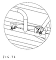
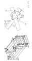
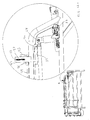
- the release mechanism is shown as detail A in enlarged version on Fig. 7a.
- the release mechanism includes an elastically displacing fitting 28 for engaging behind a hook 29.
- the transverse engaging part 30 of the fitting 28 on the shown Fig. 7a is engaging the hook 29.
- the fitting 28 is rotating about a rotatable axle 31 that extend through a bushing 32 and through an oblong recess 33.
- the bushing 32 is fastened to a pipe 14 of the sidewall on the pen 1, e.g. by welding. Due to the oblong recess 33, the fitting 28 may be displaced relative to the rotatable axle 31.
- the fitting 28 is pre-stressed with an elastic force in direction against the axle 31 and is therefore kept in place under the hook 29.
- the fitting 28 is fastened to the rear gate 4. If the rear gate 4 is pushed rearwards, the fitting 28 will thus also be displaced rearwards if the rearwards directed force is greater than the force of the forwards directed pre-stressing, when the gate 4 is closed. Thereby, the transverse engagement part 30 of the fitting 28 is released from the hook 29, which is shown on Fig. 2b. The fitting 8 is then displaced so much in rearwards direction that the axle 31 is positioned rearmost in the oblong recess 33.
- the fitting 28 may advantageously be provided with a rubber disc 15 that rests on a pipe 14 of the sidewall when the rear gate 4 is closed.
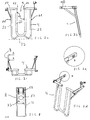
- the rear gate 4 is shown in greater detail seen from behind 4 on Fig. 2a, from the side on Fig. 2b, and from above on Fig. 2c, in closed condition and in perspective view on Fig. 2d, where the detail B is shown in enlarged condition on Fig. 2e.
- the fitting 28 includes in this case the spring mechanism that is consisting of a displaceable plate 16 with a central hole 17 through which the rotatable axle 31 (not shown on Fig. 2) is extending. Furthermore, the oblong recess 33 is outlined with broken line.
- the displaceable plate is spring loaded with springs 18 so that moving the plate 16 from its equilibrium position results in an oppositely directed spring force. In practice, the equilibrium position will be arranged so that it is close to the rear part of the oblong recess 33, which is also indicated on Fig. 7c. In this way, the fitting 28 is pre-stressed when the rotatable axle 31 is at the centre of the oblong recess 33.
- a second embodiment for pre-stressing the fitting 28' against the rotatable axle 31' is shown on Fig. 9.
- a spring 18' is provided, with one end connected to the bushing 32 and thereby indirectly to a pipe 14 of the sidewall of the pen 1 and with the second end to a projection 19 of the fitting 28.
- the pen 1 may be secured against the sow leaving the pen 1 during feeding.
- This may be achieved by providing the pen with a central locking mechanism, e.g. with a lock hook 6 for engaging a horizontal rod 7.
- the central lock mechanism may be engaged and disengaged from a central position, e.g. with a handle.
- a handle is provided in the front part of the pen 1, which can be a disadvantage, however, if one wants to disengage the locking mechanism from a place behind the pen.
- the lock hook furthermore implies a hazard for the persons staying in the pen as they risk stumbling into the lock hook 6, or to be pressed into the lock hook 6 by the sow, which can have fatal consequences for the person in question.
- the rear gate is provided with an alternative locking device 25, where the principle of a release mechanism as described in connection with Fig. 7 is supplemented with a system as explained in the following with reference to Fig. 10.
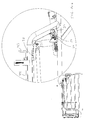
- the locking device 25 includes a rocker lock 26 that is locking against rearwards displacement of the rear gate, if a counterweight 27 of the rocker lock 26 is resting on the base 34, which is shown on Fig. 10a.
- the locking is effected by a locking pawl 35 that is provided in extension of the counterweight 27 and in the shown situation is blocking against the transverse engagement part 30' of the fitting 28' being released from the hook 9. It is noted that in this embodiment, the transverse engagement part 30' of the fitting 28' is changed compared with the embodiment shown on Figs. 7 and 9.
- rocker lock 26 If the rocker lock 26 is tilted about a rocker axle 36 so that the counterweight 27 is lifted sufficiently free from the base 34, as shown on Fig. 10b, the lock pawl 35 will pivot past the transverse engagement part 30' of the fitting 28', whereby displacement of the rear gate 4 is possible.
- a rocker lock 26 of this type is a simple means that is efficient and allow that a lock hook 6 as shown on Fig. 1 may be omitted, whereby the previously mentioned hazard associated therewith is avoided.
- a device for rocking the rocker lock may be designed in different ways.
- a preferred example is shown on Fig. 10a.
- the counterweight 27 is connected with a wire 37 that is fastened to a rod 38 which is connected to a turning device 41, as shown on Fig. 11, which is part of a central locking apparatus (not shown).
- the rocker lock 25 can be engaged by means of a rearwards displacement of the rod 38, as shown on Fig. 11a, and be disengaged by a forward displacement of the rod 38, as shown on Fig. 11b, from a central position, e.g. with a handle (not shown).
- the wire 37 is tensioned in its course over a cross-pin 41, whereby the counterweight 27 is lifted and the lock pawl 34 is pivoted past the transverse engagement part 30' of the fitting 28'.
- the central locking apparatus with the turning device 31 is typically connected at corresponding rods 38 and wires 37 to corresponding locks 25 in other pens 1.
- Identical locking devices 25 of all the pens may thus be engaged or disengaged form this central apparatus.
- this locking apparatus 40 will be designed so that all locking devices for the pens can be engaged or disengaged jointly. This simplification of the locking apparatus, however, means that individual locking of the pens is not possible, unless further means are incorporated. Such further means are explained in the following.
- These further means include a slide block 39 that supports the wire 37 by means of the cross-pin 40 between the rod 38 and the counterweight 27 of the rocker lock 26.
- the slide block 39 is designed to slide between a first position as shown on Fig. 10a and a second position as shown on Fig. 12a.
- the cross-pin 40 of the slide block 39 will support the wire 38 sufficiently in order that tensioning the wire 37 from the forwards displaced rod 38 as shown on Fig. 10b provides lifting the counterweight 27 off the base 34.
- the wire 37 is not supported by the cross-pin 40, which causes slackening of the wire 37.
- the displacement of the slide block 39 is adapted for this slacking being sufficient to the effect that slackening the wire 37 from the rod 38 does not enable lifting the counterweight 27 so much off the base 34 that displacing the rear gate rearwards is possible.
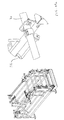
- the slide block 39 is connected with a fitting 42 which is connected to a rear handle 43, which via a connecting rod 44 is connected to a front handle 45.
- the fitting 42 is accommodated in a recess 47 of a side plate 49 by means of a z-shaped angle 46, the side plate 49 furthermore containing a spring 48 which is illustrated in perspective view in Fig. 13 and from the side in Fig. 12a.
- the connecting rod 44 By displacing the connecting rod 44 with the two handles 34,45, the z-shaped angle will change its position between the condition as illustrated on Fig. 10a to a condition as shown on Fig. 12a. While passing from one condition to the other, the spring 48 will be compressed and then extended again.
- rocker lock may also be substituted by a lock designed as a toggle joint.
- wire can be fastened on the lock pawl instead of the counterweight.
Landscapes
- Life Sciences & Earth Sciences (AREA)
- Environmental Sciences (AREA)
- Zoology (AREA)
- Animal Husbandry (AREA)
- Biodiversity & Conservation Biology (AREA)
- Housing For Livestock And Birds (AREA)
- Refuge Islands, Traffic Blockers, Or Guard Fence (AREA)
- Catching Or Destruction (AREA)
- Closing And Opening Devices For Wings, And Checks For Wings (AREA)
- Refuse Receptacles (AREA)
Priority Applications (1)
| Application Number | Priority Date | Filing Date | Title |
|---|---|---|---|
| DK03006353T DK1346632T3 (da) | 2002-03-22 | 2003-03-20 | Baglåge til husdyrbås |
Applications Claiming Priority (4)
| Application Number | Priority Date | Filing Date | Title |
|---|---|---|---|
| DK200200081 | 2002-03-22 | ||
| DKPA200200081 | 2002-03-22 | ||
| DKPA200200440 | 2002-03-22 | ||
| DK200200440 | 2002-03-22 |
Publications (3)
| Publication Number | Publication Date |
|---|---|
| EP1346632A2 true EP1346632A2 (fr) | 2003-09-24 |
| EP1346632A3 EP1346632A3 (fr) | 2004-01-14 |
| EP1346632B1 EP1346632B1 (fr) | 2005-12-07 |
Family
ID=27789987
Family Applications (1)
| Application Number | Title | Priority Date | Filing Date |
|---|---|---|---|
| EP03006353A Expired - Lifetime EP1346632B1 (fr) | 2002-03-22 | 2003-03-20 | Porte arrière pour case pour un animal |
Country Status (5)
| Country | Link |
|---|---|
| EP (1) | EP1346632B1 (fr) |
| AT (1) | ATE311745T1 (fr) |
| DE (1) | DE60302593T2 (fr) |
| DK (1) | DK1346632T3 (fr) |
| ES (1) | ES2257611T3 (fr) |
Cited By (9)
| Publication number | Priority date | Publication date | Assignee | Title |
|---|---|---|---|---|
| EP2055183A2 (fr) | 2007-10-29 | 2009-05-06 | Egebjerg International A/S | Principe de verrouillage pour la porte arrière d'une étable |
| WO2010112031A1 (fr) * | 2009-04-02 | 2010-10-07 | Ap Company Af 2009 A/S | Boîte de rétention pour animaux domestiques |
| WO2012136216A1 (fr) * | 2011-04-07 | 2012-10-11 | Egebjerg International A/S | Stalle pour animaux domestiques, de préférence pour truies, avec tige de liaison élastique |
| CN107135959A (zh) * | 2017-06-16 | 2017-09-08 | 河南和宏农牧股份有限公司 | 一种母猪产仔专用护架 |
| WO2017171624A1 (fr) * | 2016-04-01 | 2017-10-05 | Delaval Holding Ab | Module de traite, agencement de traite, et procédé de traite de groupe d'animaux |
| CN109430067A (zh) * | 2018-11-09 | 2019-03-08 | 佛山科学技术学院 | 一种哺乳母猪可折叠限位栏 |
| CN109601407A (zh) * | 2018-12-17 | 2019-04-12 | 河南牧业经济学院 | 分娩保育一体栏 |
| CN109997703A (zh) * | 2019-04-25 | 2019-07-12 | 东北农业大学 | 猪只单体限位栏门闩机构 |
| CN113115718A (zh) * | 2021-04-29 | 2021-07-16 | 禹州市瑞和农牧设备有限公司 | 一种饲喂系统的采食通道 |
Citations (1)
| Publication number | Priority date | Publication date | Assignee | Title |
|---|---|---|---|---|
| DK173957B1 (da) | 2000-10-23 | 2002-03-11 | Egebjerg Maskinfabrik As | Bås til husdyr, fortrinsvis søer, samt anvendelse heraf |
Family Cites Families (3)
| Publication number | Priority date | Publication date | Assignee | Title |
|---|---|---|---|---|
| GB2263855B (en) * | 1992-02-05 | 1995-07-05 | Aco Polymer Products Ltd | Drop stall |
| FR2793387A1 (fr) * | 1999-05-12 | 2000-11-17 | Galvelpor Sa | Stalle de refectoire pour betail |
| FR2803983A1 (fr) * | 2000-01-26 | 2001-07-27 | Union Cooperl Hunaudaye | Systeme de fermeture pour case d'elevage |
-
2003
- 2003-03-20 DK DK03006353T patent/DK1346632T3/da active
- 2003-03-20 AT AT03006353T patent/ATE311745T1/de not_active IP Right Cessation
- 2003-03-20 EP EP03006353A patent/EP1346632B1/fr not_active Expired - Lifetime
- 2003-03-20 ES ES03006353T patent/ES2257611T3/es not_active Expired - Lifetime
- 2003-03-20 DE DE60302593T patent/DE60302593T2/de not_active Expired - Fee Related
Patent Citations (2)
| Publication number | Priority date | Publication date | Assignee | Title |
|---|---|---|---|---|
| DK173957B1 (da) | 2000-10-23 | 2002-03-11 | Egebjerg Maskinfabrik As | Bås til husdyr, fortrinsvis søer, samt anvendelse heraf |
| WO2002034037A1 (fr) | 2000-10-23 | 2002-05-02 | Egebjerg Maskinfabrik A/S | Logement pour animaux domestiques, notamment les truies |
Cited By (14)
| Publication number | Priority date | Publication date | Assignee | Title |
|---|---|---|---|---|
| EP2055183A3 (fr) * | 2007-10-29 | 2013-09-04 | Egebjerg International A/S | Principe de verrouillage pour la porte arrière d'une étable |
| EP2055183A2 (fr) | 2007-10-29 | 2009-05-06 | Egebjerg International A/S | Principe de verrouillage pour la porte arrière d'une étable |
| WO2010112031A1 (fr) * | 2009-04-02 | 2010-10-07 | Ap Company Af 2009 A/S | Boîte de rétention pour animaux domestiques |
| WO2012136216A1 (fr) * | 2011-04-07 | 2012-10-11 | Egebjerg International A/S | Stalle pour animaux domestiques, de préférence pour truies, avec tige de liaison élastique |
| JP2019513020A (ja) * | 2016-04-01 | 2019-05-23 | デラヴァル ホルディング アーベー | 搾乳モジュール、搾乳装置、及び動物の群を搾乳するための方法 |
| WO2017171624A1 (fr) * | 2016-04-01 | 2017-10-05 | Delaval Holding Ab | Module de traite, agencement de traite, et procédé de traite de groupe d'animaux |
| US10980213B2 (en) | 2016-04-01 | 2021-04-20 | Delaval Holding Ab | Milking module, a milking arrangement, and a method for milking a group of animals |
| CN107135959A (zh) * | 2017-06-16 | 2017-09-08 | 河南和宏农牧股份有限公司 | 一种母猪产仔专用护架 |
| CN109430067A (zh) * | 2018-11-09 | 2019-03-08 | 佛山科学技术学院 | 一种哺乳母猪可折叠限位栏 |
| CN109430067B (zh) * | 2018-11-09 | 2023-09-26 | 佛山科学技术学院 | 一种哺乳母猪可折叠限位栏 |
| CN109601407A (zh) * | 2018-12-17 | 2019-04-12 | 河南牧业经济学院 | 分娩保育一体栏 |
| CN109601407B (zh) * | 2018-12-17 | 2023-11-03 | 河南牧业经济学院 | 分娩保育一体栏 |
| CN109997703A (zh) * | 2019-04-25 | 2019-07-12 | 东北农业大学 | 猪只单体限位栏门闩机构 |
| CN113115718A (zh) * | 2021-04-29 | 2021-07-16 | 禹州市瑞和农牧设备有限公司 | 一种饲喂系统的采食通道 |
Also Published As
| Publication number | Publication date |
|---|---|
| EP1346632A3 (fr) | 2004-01-14 |
| DE60302593D1 (de) | 2006-01-12 |
| ATE311745T1 (de) | 2005-12-15 |
| DE60302593T2 (de) | 2006-09-07 |
| DK1346632T3 (da) | 2006-04-18 |
| EP1346632B1 (fr) | 2005-12-07 |
| ES2257611T3 (es) | 2006-08-01 |
Similar Documents
| Publication | Publication Date | Title |
|---|---|---|
| US11166449B2 (en) | Cage trap with easy set and release mechanism | |
| US7861675B2 (en) | Containment apparatus for containing gestating sows | |
| EP1346632B1 (fr) | Porte arrière pour case pour un animal | |
| US20080178516A1 (en) | Humane trap for small animals | |
| CA2858568C (fr) | Stalle a fermeture automatique pour un animal | |
| US6199514B1 (en) | Method of restraining an animal within an animal squeeze, and an animal squeeze | |
| US7370451B2 (en) | Cage trap with easy set and release mechanism | |
| NZ241999A (en) | Animal headgate with slidable spring-urged yokes which lock about animal's neck | |
| KR101412501B1 (ko) | 영장류의 보정기 | |
| US20090173285A1 (en) | Locking principle for a rear gate in a pen | |
| CA2363189C (fr) | Dispositif servant a maintenir un animal en enclos ferme | |
| US4059073A (en) | Head gate | |
| NL9000107A (nl) | Voerhek. | |
| KR20210051489A (ko) | 송아지용 축사 | |
| CA1112866A (fr) | Piege humanitaire pour animaux | |
| EP2413686A1 (fr) | Boîte de rétention pour animaux domestiques | |
| US20120000433A1 (en) | Insert for a gated chute for smaller livestock | |
| US7784431B2 (en) | Animal stanchion with selectively releasable feature | |
| US3590783A (en) | Safety cow tie | |
| US9113611B1 (en) | Animal release chute apparatus | |
| CZ20031108A3 (cs) | Kóje pro domácí zvířectvo, obzvláště prasnice | |
| CA2267455C (fr) | Methode de contention d'un animal au sein d'un goulet d'attente, et goulet d'attente | |
| KR20110136397A (ko) | 가축 머리 고정장치 | |
| US20180153135A1 (en) | Portable pet restraint | |
| GB2470218A (en) | A headgate for livestock handling equipment |
Legal Events
| Date | Code | Title | Description |
|---|---|---|---|
| PUAI | Public reference made under article 153(3) epc to a published international application that has entered the european phase |
Free format text: ORIGINAL CODE: 0009012 |
|
| AK | Designated contracting states |
Kind code of ref document: A2 Designated state(s): AT BE BG CH CY CZ DE DK EE ES FI FR GB GR HU IE IT LI LU MC NL PT RO SE SI SK TR |
|
| AX | Request for extension of the european patent |
Extension state: AL LT LV MK |
|
| PUAL | Search report despatched |
Free format text: ORIGINAL CODE: 0009013 |
|
| AK | Designated contracting states |
Kind code of ref document: A3 Designated state(s): AT BE BG CH CY CZ DE DK EE ES FI FR GB GR HU IE IT LI LU MC NL PT RO SE SI SK TR |
|
| AX | Request for extension of the european patent |
Extension state: AL LT LV MK |
|
| RIC1 | Information provided on ipc code assigned before grant |
Ipc: 7A 01K 1/00 B Ipc: 7A 01K 1/02 A |
|
| 17P | Request for examination filed |
Effective date: 20040628 |
|
| AKX | Designation fees paid |
Designated state(s): AT BE BG CH CY CZ DE DK EE ES FI FR GB GR HU IE IT LI LU MC NL PT RO SE SI SK TR |
|
| 17Q | First examination report despatched |
Effective date: 20040914 |
|
| GRAP | Despatch of communication of intention to grant a patent |
Free format text: ORIGINAL CODE: EPIDOSNIGR1 |
|
| GRAS | Grant fee paid |
Free format text: ORIGINAL CODE: EPIDOSNIGR3 |
|
| GRAA | (expected) grant |
Free format text: ORIGINAL CODE: 0009210 |
|
| GRAL | Information related to payment of fee for publishing/printing deleted |
Free format text: ORIGINAL CODE: EPIDOSDIGR3 |
|
| GRAS | Grant fee paid |
Free format text: ORIGINAL CODE: EPIDOSNIGR3 |
|
| AK | Designated contracting states |
Kind code of ref document: B1 Designated state(s): AT BE BG CH CY CZ DE DK EE ES FI FR GB GR HU IE IT LI LU MC NL PT RO SE SI SK TR |
|
| PG25 | Lapsed in a contracting state [announced via postgrant information from national office to epo] |
Ref country code: SI Free format text: LAPSE BECAUSE OF FAILURE TO SUBMIT A TRANSLATION OF THE DESCRIPTION OR TO PAY THE FEE WITHIN THE PRESCRIBED TIME-LIMIT Effective date: 20051207 Ref country code: RO Free format text: LAPSE BECAUSE OF FAILURE TO SUBMIT A TRANSLATION OF THE DESCRIPTION OR TO PAY THE FEE WITHIN THE PRESCRIBED TIME-LIMIT Effective date: 20051207 Ref country code: BE Free format text: LAPSE BECAUSE OF FAILURE TO SUBMIT A TRANSLATION OF THE DESCRIPTION OR TO PAY THE FEE WITHIN THE PRESCRIBED TIME-LIMIT Effective date: 20051207 Ref country code: IT Free format text: LAPSE BECAUSE OF FAILURE TO SUBMIT A TRANSLATION OF THE DESCRIPTION OR TO PAY THE FEE WITHIN THE PRESCRIBED TIME-LIMIT;WARNING: LAPSES OF ITALIAN PATENTS WITH EFFECTIVE DATE BEFORE 2007 MAY HAVE OCCURRED AT ANY TIME BEFORE 2007. THE CORRECT EFFECTIVE DATE MAY BE DIFFERENT FROM THE ONE RECORDED. Effective date: 20051207 Ref country code: AT Free format text: LAPSE BECAUSE OF FAILURE TO SUBMIT A TRANSLATION OF THE DESCRIPTION OR TO PAY THE FEE WITHIN THE PRESCRIBED TIME-LIMIT Effective date: 20051207 Ref country code: SK Free format text: LAPSE BECAUSE OF FAILURE TO SUBMIT A TRANSLATION OF THE DESCRIPTION OR TO PAY THE FEE WITHIN THE PRESCRIBED TIME-LIMIT Effective date: 20051207 Ref country code: CH Free format text: LAPSE BECAUSE OF FAILURE TO SUBMIT A TRANSLATION OF THE DESCRIPTION OR TO PAY THE FEE WITHIN THE PRESCRIBED TIME-LIMIT Effective date: 20051207 Ref country code: LI Free format text: LAPSE BECAUSE OF FAILURE TO SUBMIT A TRANSLATION OF THE DESCRIPTION OR TO PAY THE FEE WITHIN THE PRESCRIBED TIME-LIMIT Effective date: 20051207 Ref country code: CZ Free format text: LAPSE BECAUSE OF FAILURE TO SUBMIT A TRANSLATION OF THE DESCRIPTION OR TO PAY THE FEE WITHIN THE PRESCRIBED TIME-LIMIT Effective date: 20051207 |
|
| REG | Reference to a national code |
Ref country code: GB Ref legal event code: FG4D |
|
| REG | Reference to a national code |
Ref country code: CH Ref legal event code: EP |
|
| REG | Reference to a national code |
Ref country code: IE Ref legal event code: FG4D |
|
| REF | Corresponds to: |
Ref document number: 60302593 Country of ref document: DE Date of ref document: 20060112 Kind code of ref document: P |
|
| PG25 | Lapsed in a contracting state [announced via postgrant information from national office to epo] |
Ref country code: GR Free format text: LAPSE BECAUSE OF FAILURE TO SUBMIT A TRANSLATION OF THE DESCRIPTION OR TO PAY THE FEE WITHIN THE PRESCRIBED TIME-LIMIT Effective date: 20060307 Ref country code: BG Free format text: LAPSE BECAUSE OF FAILURE TO SUBMIT A TRANSLATION OF THE DESCRIPTION OR TO PAY THE FEE WITHIN THE PRESCRIBED TIME-LIMIT Effective date: 20060307 Ref country code: SE Free format text: LAPSE BECAUSE OF FAILURE TO SUBMIT A TRANSLATION OF THE DESCRIPTION OR TO PAY THE FEE WITHIN THE PRESCRIBED TIME-LIMIT Effective date: 20060307 |
|
| PG25 | Lapsed in a contracting state [announced via postgrant information from national office to epo] |
Ref country code: IE Free format text: LAPSE BECAUSE OF NON-PAYMENT OF DUE FEES Effective date: 20060320 |
|
| PG25 | Lapsed in a contracting state [announced via postgrant information from national office to epo] |
Ref country code: MC Free format text: LAPSE BECAUSE OF NON-PAYMENT OF DUE FEES Effective date: 20060331 Ref country code: LU Free format text: LAPSE BECAUSE OF NON-PAYMENT OF DUE FEES Effective date: 20060331 |
|
| REG | Reference to a national code |
Ref country code: DK Ref legal event code: T3 |
|
| PG25 | Lapsed in a contracting state [announced via postgrant information from national office to epo] |
Ref country code: PT Free format text: LAPSE BECAUSE OF FAILURE TO SUBMIT A TRANSLATION OF THE DESCRIPTION OR TO PAY THE FEE WITHIN THE PRESCRIBED TIME-LIMIT Effective date: 20060508 |
|
| PG25 | Lapsed in a contracting state [announced via postgrant information from national office to epo] |
Ref country code: HU Free format text: LAPSE BECAUSE OF FAILURE TO SUBMIT A TRANSLATION OF THE DESCRIPTION OR TO PAY THE FEE WITHIN THE PRESCRIBED TIME-LIMIT Effective date: 20060608 |
|
| REG | Reference to a national code |
Ref country code: CH Ref legal event code: PL |
|
| REG | Reference to a national code |
Ref country code: ES Ref legal event code: FG2A Ref document number: 2257611 Country of ref document: ES Kind code of ref document: T3 |
|
| ET | Fr: translation filed | ||
| PLBE | No opposition filed within time limit |
Free format text: ORIGINAL CODE: 0009261 |
|
| STAA | Information on the status of an ep patent application or granted ep patent |
Free format text: STATUS: NO OPPOSITION FILED WITHIN TIME LIMIT |
|
| 26N | No opposition filed |
Effective date: 20060908 |
|
| REG | Reference to a national code |
Ref country code: IE Ref legal event code: MM4A |
|
| PG25 | Lapsed in a contracting state [announced via postgrant information from national office to epo] |
Ref country code: EE Free format text: LAPSE BECAUSE OF FAILURE TO SUBMIT A TRANSLATION OF THE DESCRIPTION OR TO PAY THE FEE WITHIN THE PRESCRIBED TIME-LIMIT Effective date: 20051207 |
|
| PG25 | Lapsed in a contracting state [announced via postgrant information from national office to epo] |
Ref country code: TR Free format text: LAPSE BECAUSE OF FAILURE TO SUBMIT A TRANSLATION OF THE DESCRIPTION OR TO PAY THE FEE WITHIN THE PRESCRIBED TIME-LIMIT Effective date: 20051207 |
|
| PG25 | Lapsed in a contracting state [announced via postgrant information from national office to epo] |
Ref country code: CY Free format text: LAPSE BECAUSE OF FAILURE TO SUBMIT A TRANSLATION OF THE DESCRIPTION OR TO PAY THE FEE WITHIN THE PRESCRIBED TIME-LIMIT Effective date: 20051207 |
|
| PGFP | Annual fee paid to national office [announced via postgrant information from national office to epo] |
Ref country code: DK Payment date: 20090327 Year of fee payment: 7 Ref country code: ES Payment date: 20090330 Year of fee payment: 7 |
|
| PGFP | Annual fee paid to national office [announced via postgrant information from national office to epo] |
Ref country code: FI Payment date: 20090317 Year of fee payment: 7 Ref country code: NL Payment date: 20090317 Year of fee payment: 7 |
|
| PGFP | Annual fee paid to national office [announced via postgrant information from national office to epo] |
Ref country code: GB Payment date: 20090319 Year of fee payment: 7 |
|
| PGFP | Annual fee paid to national office [announced via postgrant information from national office to epo] |
Ref country code: DE Payment date: 20090313 Year of fee payment: 7 |
|
| PGFP | Annual fee paid to national office [announced via postgrant information from national office to epo] |
Ref country code: FR Payment date: 20090317 Year of fee payment: 7 |
|
| REG | Reference to a national code |
Ref country code: NL Ref legal event code: V1 Effective date: 20101001 |
|
| REG | Reference to a national code |
Ref country code: DK Ref legal event code: EBP |
|
| GBPC | Gb: european patent ceased through non-payment of renewal fee |
Effective date: 20100320 |
|
| PG25 | Lapsed in a contracting state [announced via postgrant information from national office to epo] |
Ref country code: FI Free format text: LAPSE BECAUSE OF NON-PAYMENT OF DUE FEES Effective date: 20100320 |
|
| REG | Reference to a national code |
Ref country code: FR Ref legal event code: ST Effective date: 20101130 |
|
| PG25 | Lapsed in a contracting state [announced via postgrant information from national office to epo] |
Ref country code: NL Free format text: LAPSE BECAUSE OF NON-PAYMENT OF DUE FEES Effective date: 20101001 Ref country code: FR Free format text: LAPSE BECAUSE OF NON-PAYMENT OF DUE FEES Effective date: 20100331 |
|
| PG25 | Lapsed in a contracting state [announced via postgrant information from national office to epo] |
Ref country code: DE Free format text: LAPSE BECAUSE OF NON-PAYMENT OF DUE FEES Effective date: 20101001 |
|
| PG25 | Lapsed in a contracting state [announced via postgrant information from national office to epo] |
Ref country code: GB Free format text: LAPSE BECAUSE OF NON-PAYMENT OF DUE FEES Effective date: 20100320 |
|
| REG | Reference to a national code |
Ref country code: ES Ref legal event code: FD2A Effective date: 20110415 |
|
| PG25 | Lapsed in a contracting state [announced via postgrant information from national office to epo] |
Ref country code: DK Free format text: LAPSE BECAUSE OF NON-PAYMENT OF DUE FEES Effective date: 20100331 |
|
| PG25 | Lapsed in a contracting state [announced via postgrant information from national office to epo] |
Ref country code: ES Free format text: LAPSE BECAUSE OF NON-PAYMENT OF DUE FEES Effective date: 20110404 |
|
| PG25 | Lapsed in a contracting state [announced via postgrant information from national office to epo] |
Ref country code: ES Free format text: LAPSE BECAUSE OF NON-PAYMENT OF DUE FEES Effective date: 20100321 |