EP1346812A1 - Verfahren und Vorrichtung zur energieorientierten Optimierung von zyklisch ablaufenden Maschinenprozessen - Google Patents
Verfahren und Vorrichtung zur energieorientierten Optimierung von zyklisch ablaufenden Maschinenprozessen Download PDFInfo
- Publication number
- EP1346812A1 EP1346812A1 EP03005884A EP03005884A EP1346812A1 EP 1346812 A1 EP1346812 A1 EP 1346812A1 EP 03005884 A EP03005884 A EP 03005884A EP 03005884 A EP03005884 A EP 03005884A EP 1346812 A1 EP1346812 A1 EP 1346812A1
- Authority
- EP
- European Patent Office
- Prior art keywords
- cycle
- energy consumption
- energy
- machine
- machine parameters
- Prior art date
- Legal status (The legal status is an assumption and is not a legal conclusion. Google has not performed a legal analysis and makes no representation as to the accuracy of the status listed.)
- Granted
Links
- 238000000034 method Methods 0.000 title claims abstract description 50
- 238000005457 optimization Methods 0.000 title claims description 13
- 125000004122 cyclic group Chemical group 0.000 title 1
- 238000005265 energy consumption Methods 0.000 claims description 36
- 238000001746 injection moulding Methods 0.000 claims description 20
- 229920003023 plastic Polymers 0.000 claims description 13
- 239000004033 plastic Substances 0.000 claims description 13
- 238000002347 injection Methods 0.000 claims description 12
- 239000007924 injection Substances 0.000 claims description 12
- 238000011156 evaluation Methods 0.000 claims description 11
- 239000000463 material Substances 0.000 claims description 10
- 238000012545 processing Methods 0.000 claims description 9
- 238000004519 manufacturing process Methods 0.000 claims description 6
- 238000005259 measurement Methods 0.000 claims description 5
- 238000003860 storage Methods 0.000 claims description 4
- 238000011161 development Methods 0.000 claims description 3
- 230000036961 partial effect Effects 0.000 claims description 3
- 230000000750 progressive effect Effects 0.000 claims description 2
- 238000010438 heat treatment Methods 0.000 description 5
- 238000004458 analytical method Methods 0.000 description 3
- 238000001816 cooling Methods 0.000 description 3
- 239000007921 spray Substances 0.000 description 3
- 238000012935 Averaging Methods 0.000 description 2
- 230000015572 biosynthetic process Effects 0.000 description 2
- 238000010586 diagram Methods 0.000 description 2
- 238000004512 die casting Methods 0.000 description 2
- 125000002015 acyclic group Chemical group 0.000 description 1
- 229910052782 aluminium Inorganic materials 0.000 description 1
- XAGFODPZIPBFFR-UHFFFAOYSA-N aluminium Chemical compound [Al] XAGFODPZIPBFFR-UHFFFAOYSA-N 0.000 description 1
- 238000000071 blow moulding Methods 0.000 description 1
- 238000004364 calculation method Methods 0.000 description 1
- 229910010293 ceramic material Inorganic materials 0.000 description 1
- 238000010276 construction Methods 0.000 description 1
- 230000007547 defect Effects 0.000 description 1
- 238000013461 design Methods 0.000 description 1
- 238000001514 detection method Methods 0.000 description 1
- 230000005611 electricity Effects 0.000 description 1
- 230000007613 environmental effect Effects 0.000 description 1
- 230000002452 interceptive effect Effects 0.000 description 1
- 238000012423 maintenance Methods 0.000 description 1
- 229910052751 metal Inorganic materials 0.000 description 1
- 239000002184 metal Substances 0.000 description 1
- 238000012544 monitoring process Methods 0.000 description 1
- 230000003449 preventive effect Effects 0.000 description 1
- 230000035945 sensitivity Effects 0.000 description 1
- 230000036962 time dependent Effects 0.000 description 1
- 230000000007 visual effect Effects 0.000 description 1
- 238000003466 welding Methods 0.000 description 1
Images


Classifications
-
- B—PERFORMING OPERATIONS; TRANSPORTING
- B29—WORKING OF PLASTICS; WORKING OF SUBSTANCES IN A PLASTIC STATE IN GENERAL
- B29C—SHAPING OR JOINING OF PLASTICS; SHAPING OF MATERIAL IN A PLASTIC STATE, NOT OTHERWISE PROVIDED FOR; AFTER-TREATMENT OF THE SHAPED PRODUCTS, e.g. REPAIRING
- B29C45/00—Injection moulding, i.e. forcing the required volume of moulding material through a nozzle into a closed mould; Apparatus therefor
- B29C45/17—Component parts, details or accessories; Auxiliary operations
- B29C45/76—Measuring, controlling or regulating
- B29C45/7666—Measuring, controlling or regulating of power or energy, e.g. integral function of force
-
- B—PERFORMING OPERATIONS; TRANSPORTING
- B29—WORKING OF PLASTICS; WORKING OF SUBSTANCES IN A PLASTIC STATE IN GENERAL
- B29C—SHAPING OR JOINING OF PLASTICS; SHAPING OF MATERIAL IN A PLASTIC STATE, NOT OTHERWISE PROVIDED FOR; AFTER-TREATMENT OF THE SHAPED PRODUCTS, e.g. REPAIRING
- B29C45/00—Injection moulding, i.e. forcing the required volume of moulding material through a nozzle into a closed mould; Apparatus therefor
- B29C45/17—Component parts, details or accessories; Auxiliary operations
- B29C45/76—Measuring, controlling or regulating
- B29C45/766—Measuring, controlling or regulating the setting or resetting of moulding conditions, e.g. before starting a cycle
-
- B—PERFORMING OPERATIONS; TRANSPORTING
- B29—WORKING OF PLASTICS; WORKING OF SUBSTANCES IN A PLASTIC STATE IN GENERAL
- B29C—SHAPING OR JOINING OF PLASTICS; SHAPING OF MATERIAL IN A PLASTIC STATE, NOT OTHERWISE PROVIDED FOR; AFTER-TREATMENT OF THE SHAPED PRODUCTS, e.g. REPAIRING
- B29C45/00—Injection moulding, i.e. forcing the required volume of moulding material through a nozzle into a closed mould; Apparatus therefor
- B29C45/17—Component parts, details or accessories; Auxiliary operations
- B29C45/76—Measuring, controlling or regulating
- B29C2045/7606—Controlling or regulating the display unit
-
- B—PERFORMING OPERATIONS; TRANSPORTING
- B29—WORKING OF PLASTICS; WORKING OF SUBSTANCES IN A PLASTIC STATE IN GENERAL
- B29C—SHAPING OR JOINING OF PLASTICS; SHAPING OF MATERIAL IN A PLASTIC STATE, NOT OTHERWISE PROVIDED FOR; AFTER-TREATMENT OF THE SHAPED PRODUCTS, e.g. REPAIRING
- B29C2945/00—Indexing scheme relating to injection moulding, i.e. forcing the required volume of moulding material through a nozzle into a closed mould
- B29C2945/76—Measuring, controlling or regulating
- B29C2945/76003—Measured parameter
- B29C2945/76026—Energy, power
- B29C2945/7603—Power
-
- B—PERFORMING OPERATIONS; TRANSPORTING
- B29—WORKING OF PLASTICS; WORKING OF SUBSTANCES IN A PLASTIC STATE IN GENERAL
- B29C—SHAPING OR JOINING OF PLASTICS; SHAPING OF MATERIAL IN A PLASTIC STATE, NOT OTHERWISE PROVIDED FOR; AFTER-TREATMENT OF THE SHAPED PRODUCTS, e.g. REPAIRING
- B29C2945/00—Indexing scheme relating to injection moulding, i.e. forcing the required volume of moulding material through a nozzle into a closed mould
- B29C2945/76—Measuring, controlling or regulating
- B29C2945/76003—Measured parameter
- B29C2945/76033—Electric current or voltage
-
- B—PERFORMING OPERATIONS; TRANSPORTING
- B29—WORKING OF PLASTICS; WORKING OF SUBSTANCES IN A PLASTIC STATE IN GENERAL
- B29C—SHAPING OR JOINING OF PLASTICS; SHAPING OF MATERIAL IN A PLASTIC STATE, NOT OTHERWISE PROVIDED FOR; AFTER-TREATMENT OF THE SHAPED PRODUCTS, e.g. REPAIRING
- B29C2945/00—Indexing scheme relating to injection moulding, i.e. forcing the required volume of moulding material through a nozzle into a closed mould
- B29C2945/76—Measuring, controlling or regulating
- B29C2945/76177—Location of measurement
- B29C2945/7618—Injection unit
- B29C2945/7619—Injection unit barrel
-
- B—PERFORMING OPERATIONS; TRANSPORTING
- B29—WORKING OF PLASTICS; WORKING OF SUBSTANCES IN A PLASTIC STATE IN GENERAL
- B29C—SHAPING OR JOINING OF PLASTICS; SHAPING OF MATERIAL IN A PLASTIC STATE, NOT OTHERWISE PROVIDED FOR; AFTER-TREATMENT OF THE SHAPED PRODUCTS, e.g. REPAIRING
- B29C2945/00—Indexing scheme relating to injection moulding, i.e. forcing the required volume of moulding material through a nozzle into a closed mould
- B29C2945/76—Measuring, controlling or regulating
- B29C2945/76177—Location of measurement
- B29C2945/7618—Injection unit
- B29C2945/76214—Injection unit drive means
-
- B—PERFORMING OPERATIONS; TRANSPORTING
- B29—WORKING OF PLASTICS; WORKING OF SUBSTANCES IN A PLASTIC STATE IN GENERAL
- B29C—SHAPING OR JOINING OF PLASTICS; SHAPING OF MATERIAL IN A PLASTIC STATE, NOT OTHERWISE PROVIDED FOR; AFTER-TREATMENT OF THE SHAPED PRODUCTS, e.g. REPAIRING
- B29C2945/00—Indexing scheme relating to injection moulding, i.e. forcing the required volume of moulding material through a nozzle into a closed mould
- B29C2945/76—Measuring, controlling or regulating
- B29C2945/76177—Location of measurement
- B29C2945/76224—Closure or clamping unit
- B29C2945/7623—Closure or clamping unit clamping or closing drive means
-
- B—PERFORMING OPERATIONS; TRANSPORTING
- B29—WORKING OF PLASTICS; WORKING OF SUBSTANCES IN A PLASTIC STATE IN GENERAL
- B29C—SHAPING OR JOINING OF PLASTICS; SHAPING OF MATERIAL IN A PLASTIC STATE, NOT OTHERWISE PROVIDED FOR; AFTER-TREATMENT OF THE SHAPED PRODUCTS, e.g. REPAIRING
- B29C2945/00—Indexing scheme relating to injection moulding, i.e. forcing the required volume of moulding material through a nozzle into a closed mould
- B29C2945/76—Measuring, controlling or regulating
- B29C2945/76177—Location of measurement
- B29C2945/76254—Mould
- B29C2945/76257—Mould cavity
- B29C2945/7626—Mould cavity cavity walls
-
- B—PERFORMING OPERATIONS; TRANSPORTING
- B29—WORKING OF PLASTICS; WORKING OF SUBSTANCES IN A PLASTIC STATE IN GENERAL
- B29C—SHAPING OR JOINING OF PLASTICS; SHAPING OF MATERIAL IN A PLASTIC STATE, NOT OTHERWISE PROVIDED FOR; AFTER-TREATMENT OF THE SHAPED PRODUCTS, e.g. REPAIRING
- B29C2945/00—Indexing scheme relating to injection moulding, i.e. forcing the required volume of moulding material through a nozzle into a closed mould
- B29C2945/76—Measuring, controlling or regulating
- B29C2945/76344—Phase or stage of measurement
- B29C2945/76367—Metering
-
- B—PERFORMING OPERATIONS; TRANSPORTING
- B29—WORKING OF PLASTICS; WORKING OF SUBSTANCES IN A PLASTIC STATE IN GENERAL
- B29C—SHAPING OR JOINING OF PLASTICS; SHAPING OF MATERIAL IN A PLASTIC STATE, NOT OTHERWISE PROVIDED FOR; AFTER-TREATMENT OF THE SHAPED PRODUCTS, e.g. REPAIRING
- B29C2945/00—Indexing scheme relating to injection moulding, i.e. forcing the required volume of moulding material through a nozzle into a closed mould
- B29C2945/76—Measuring, controlling or regulating
- B29C2945/76494—Controlled parameter
- B29C2945/76518—Energy, power
-
- B—PERFORMING OPERATIONS; TRANSPORTING
- B29—WORKING OF PLASTICS; WORKING OF SUBSTANCES IN A PLASTIC STATE IN GENERAL
- B29C—SHAPING OR JOINING OF PLASTICS; SHAPING OF MATERIAL IN A PLASTIC STATE, NOT OTHERWISE PROVIDED FOR; AFTER-TREATMENT OF THE SHAPED PRODUCTS, e.g. REPAIRING
- B29C2945/00—Indexing scheme relating to injection moulding, i.e. forcing the required volume of moulding material through a nozzle into a closed mould
- B29C2945/76—Measuring, controlling or regulating
- B29C2945/76494—Controlled parameter
- B29C2945/76525—Electric current or voltage
-
- B—PERFORMING OPERATIONS; TRANSPORTING
- B29—WORKING OF PLASTICS; WORKING OF SUBSTANCES IN A PLASTIC STATE IN GENERAL
- B29C—SHAPING OR JOINING OF PLASTICS; SHAPING OF MATERIAL IN A PLASTIC STATE, NOT OTHERWISE PROVIDED FOR; AFTER-TREATMENT OF THE SHAPED PRODUCTS, e.g. REPAIRING
- B29C2945/00—Indexing scheme relating to injection moulding, i.e. forcing the required volume of moulding material through a nozzle into a closed mould
- B29C2945/76—Measuring, controlling or regulating
- B29C2945/76929—Controlling method
- B29C2945/76939—Using stored or historical data sets
- B29C2945/76943—Using stored or historical data sets compare with thresholds
-
- B—PERFORMING OPERATIONS; TRANSPORTING
- B29—WORKING OF PLASTICS; WORKING OF SUBSTANCES IN A PLASTIC STATE IN GENERAL
- B29C—SHAPING OR JOINING OF PLASTICS; SHAPING OF MATERIAL IN A PLASTIC STATE, NOT OTHERWISE PROVIDED FOR; AFTER-TREATMENT OF THE SHAPED PRODUCTS, e.g. REPAIRING
- B29C2945/00—Indexing scheme relating to injection moulding, i.e. forcing the required volume of moulding material through a nozzle into a closed mould
- B29C2945/76—Measuring, controlling or regulating
- B29C2945/76929—Controlling method
- B29C2945/76939—Using stored or historical data sets
- B29C2945/76946—Using stored or historical data sets using an expert system, i.e. the system possesses a database in which human experience is stored, e.g. to help interfering the possible cause of a fault
Definitions
- the invention relates to a method for energy-oriented optimization of cyclically ongoing machine processes, in particular injection molding processes on injection molding machines for processing plastics and other plasticizable materials according to claim 1 and an apparatus for performing this method according to claim 9.
- the method can preferably be used in the plastics processing and in the metal processing Industry, for example in connection with plastic injection molding machines, Blow molding machines, die casting machines, aluminum die casting machines, in connection with presses or welding equipment, if cyclical ongoing processes take place in which from cycle to cycle using suitable sensors the energy consumption is recorded.
- EP 1 020 279 B1 discloses a display device for displaying the power consumption known from cyclically operating devices.
- the respective energy consumption individual power consuming elements with the drive or the Control to do is recorded individually. These values then become common transferred per cycle so that a cycle consideration and a comparison of different Cycles or sections of cycle groups with each other is possible.
- This comparison can be used to detect faults, the influence of changes the machine setting parameters for energy consumption are recorded, or it is possible to increase the average energy per cycle or per manufactured part determine. A determination of what impact on energy consumption, however Cause changes in the cycle, or even an optimization of individual sections in the cycle to each other in terms of energy are not possible.
- EP 0 573 912 B1 describes a screen-based method for interactive control an injection molding machine is known, which in particular gives the fitter the opportunity there to build up the spray cycle sensibly.
- the device is based on a integrated expert knowledge able to give the user only the more meaningful To provide steps as a selection for programming the cycle.
- This control is on the market for the Arburg under the brand name "Selogica” GmbH + Co. known.
- EP 0 784 535 B1 also describes a method for controlling the quality of molded parts known. This process involves a variety of different Parameters are recorded, broken down, and attempted using key figure models a dependency between machine setting variable and quality characteristic to achieve. Although quality features are already taken into account there Energy considerations have an impact on the costs of molded part production not considered.
- the object of the present invention based on a method and a device for energy-oriented optimization of cyclical machine processes.
- the dosing process described above can be accomplished by reducing the Target speed lead to a better efficiency of the dosing axis and thus to lower machine power consumption and partly non-linear Connections also to energy minimization. Thereby already found Process optima such as productivity or part quality are not affected.
- the individual energy consumption sectors can preferably be related to the cycle being represented. This is the direct connection between the individual process steps visually recognizable for the user with the respective energy consumption.
- the user is preferably further supported in that in addition to the Absolute display graphically or numerically also a tendency display in the individual Cycle steps take place, whereby a change e.g. during the running-in phase is also recognizable as made by the user on the basis of the energy analysis Changes to the machine parameters.
- the method and the device are described below using an injection molding machine, preferably an injection molding machine for processing plastics and other plasticizable materials such as powdery or ceramic materials explained.
- an injection molding machine preferably an injection molding machine for processing plastics and other plasticizable materials such as powdery or ceramic materials explained.
- the method can be used in other areas use, in which cyclical processes for the production (original forming) or processing (reshaping) of products.
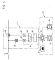
- Figure 1 shows a block diagram of a plastic injection molding machine, top left the mold clamping unit F and the injection molding unit S at the top right.
- Fig. 1 shows a fully hydraulic injection molding machine, but parts of the hydraulic Consumers or all drives can be replaced by electrical drives. anyway the process is independent of the drive systems used of the individual axes. This can be done both in a fully hydraulic machine the energy required in sections is recorded by using a known effective power meter 10 directly after the main switch the machine in e.g. multi-phase supply line the total power consumption is measured. It is also possible to measure differentiated according to consumers, e.g.
- FIG. 1 shows a power meter 11 for the hydraulic drive motor (here: Pump 18) and a power meter 11 'for the heating element 24.
- the determined Values are e.g. transmitted to the controller 12.
- cyclical Consumers such as along the movement axes of the machine and acyclic basic consumers such as the heating in the power consumption are advantageously recorded and measured separately in order to make the optimization task more successful to be able to fulfill.
- the locking unit 23 is first actuated by the between stationary mold carrier 20 and movable mold carrier 21 usually accommodated, to close the injection mold, not shown in the drawing.
- the control 12 controls the valve 13. If the form is closed, the Mold clamping unit F applied the locking pressure while plasticized at the same time Material from the plasticizing cylinder 28 by an axial movement of the screw conveyor 27 injected through the nozzle 26 into the mold cavity of the injection mold becomes.
- the controller 12 controls the valve 16 for actuating the injection unit 30 on. The hydraulic medium required for this is available via the pump 18 posed. If the mold cavity is filled, the injection molding unit S in connection with the mold clamping unit F while maintaining the locking pressure built up until the molded part has solidified.
- the metering motor 29 can already use the screw conveyor 27 the material can be dosed for the next injection cycle.
- the metering motor 29 is controlled via the valve 17.
- the Plasticizing cylinder 28 supplied with heat along its length via heating elements 24, which can be detected via the power meter 11 '.
- the tool is opened by means of the clamping unit 23 using the valve 13 and the molded part is ejected by means of the ejector 22 using the valve 14.
- the next cycle can then begin.
- a drive cylinder 25 is provided on the injection mold and can be controlled via valve 15 is.
- the process is intended to optimize manual and automatic energy consumption enable the machine. For this, given process setting variables and actual values additionally on the machine a more or less differentiated rms value power measurement (in the supply line or separately according to individual consumer groups) in real time during the ongoing cyclical process on the machine carried out and the results of the controller 12 for further processing made available via an analog or digital interface.
- the machine control provides the optimizing operator with e.g. first in graphical form Performance curve with all possibilities such as reference value formation, averaging, Tolerance curve formation and the like are available, as is the case for a graphic actual value representation and processing are state of the art.
- the Optimizing operator with e.g. first in graphical form Performance curve with all possibilities such as reference value formation, averaging, Tolerance curve formation and the like are available, as is the case for a graphic actual value representation and processing are state of the art.
- the Display automatically the section-by-section cycle division into sections using symbolic or other graphic marking of the power curve sections appears.
- the machine parameters that have been set or that result from the setting per cycle e.g. detected by sensors.
- These sensors are the usual sensors on the machine, such as temperature sensors, Pressure gauges and the like.
- the controller 12 also the machine parameters set by the user are known as inputs. additional the actually required power according to the power meters 10, 11, 11 ' determined.
- Current meter 40 and voltmeter 41 used in addition.
- the energy consumption can be determined from the values determined in this way by means of an evaluation unit A preferably from the subsections in cycles and / or for subsections of the Cycle can be determined.
- an evaluation unit A is in particular in FIG. 4 shown for the electrical detection of energy.
- the active power meter L is arranged.
- the signals from Current meter 40 and voltmeter 41 are amplified via amplifiers 42, 43.
- the signals voltage U and current I obtained in this way are in a multiplier 44 multiplied together.
- the product obtained in this way is used to determine the energy consumed by means of integrator 45 integrated over time. That energy will added to total energy in summer 46.
- Expert knowledge that is based on is preferably stored in a storage means 49
- Proposals based on the parameters determined and on the basis of energy consumption to optimize energy consumption An example of a plastic injection molding machine would be dosing the material again.
- the dosing time is usually overlaid by a significantly longer cooling time in the mold.
- Storage means 49 via the display unit 19 suggest the user the dosing speed to change or reduce, in order to increase the energy positively influence.
- the total energy consumption can be represented by symbol 97.
- the Symbols are represented by graph 31 of the energy consumption of a cycle over time.
- the displays 70 to 77 show the respective parts or the entire cycle assigned absolute values of energy consumption.
- the representation of each Energy consumption sectors related to the injection cycle can thus be in the direct Connection of the individual process steps, represented by the symbols 90 up to 96.
- Another possibility and support is in the trend indicators 80 to 87 can be seen, in addition to the absolute display graphically or numerically the progressive development occurring in the individual cycle steps display of energy consumption. This allows a change e.g. while the run-in phase as well as the sequence of user-made ones Changes.
- a graphical representation can also have a shape according to FIG. 3, again The symbols for the spray cycle are shown in the lower row, while the individual cycles are compared with each other using bar charts. Depending on the results obtained, manual or automatic actuators can be used for setting optimized machine parameters.
- FIG. 1 In the case of hydraulic consumers, the energy supplied to them is shown in FIG. 1 e.g. in the form of what is required for the respective consumer or the machine as a whole Measure electricity consumption. With electrical consumers or electrical Machines, as already explained, will take place in accordance with FIG. 4.
- On the operating unit is preferably provided with a manual actuation button his. As soon as a cyclical machine from the point of view of the If the operator has already set the optimal spray cycle, he can press this button and starts the energy acquisition and analysis.
Landscapes
- Engineering & Computer Science (AREA)
- Manufacturing & Machinery (AREA)
- Mechanical Engineering (AREA)
- Injection Moulding Of Plastics Or The Like (AREA)
- Feedback Control In General (AREA)
Abstract
Description
- Fig. 1
- Ein Blockschaubild einer Spritzgießmaschine, nämlich einer Kunststoffspritzgießmaschine,
- Fig. 2
- eine Bildschirmansicht mit einem die Energie angebenden graphischen Verlauf über die Zeit eines Zyklus mit zugeordneten Symbolen,
- Fig. 3
- eine Bildschirmansicht mit Teilabschnittweisen Balkendiagrammen,
- Fig. 4
- die Meßeinrichtung an strombetriebenen Verbrauchern,
- Fig. 5
- eine Leistungsmesskurve mit Referenzkurve und Messcursor,
- Fig. 6
- eine abschnittsweise Energieauswertung.
- 90
- Werkzeug, Schließen
- 91
- Einspritzen
- 92
- Nachdruck
- 93
- Dosieren
- 94
- Abkühlen
- 95
- Förmteil ausstoßen
- 96
- Werkzeug öffnen
- 10
- Leistungsmesser (gesamt)
- 11
- Leistungsmesser
- 11'
- Leistungsmesser für 24
- 12
- Steuerung
- 13-17
- Ventile
- 18
- Pumpe
- 19
- Anzeigeeinheit
- 20
- Stationärer Formträger
- 21
- Beweglicher Formträger
- 22
- Ausstoßer
- 23
- Schließeinheit
- 24
- Heizelement
- 25
- Fahrzylinder
- 26
- Düse
- 27
- Schnecke
- 28
- Plastifizierzylinder
- 29
- Dosiermotor
- 30
- Einspritzzylinder
- 31
- Graph
- 40
- Strommesser
- 41
- Spannungsmesser
- 42, 43
- Verstärker
- 44
- Multiplizierer
- 45
- Integrierer
- 46
- Summierer
- 47
- Eingabeeinheit
- 48
- Speichermittel
- 70-77
- Verbrauchsanzeige
- 80-87
- Tendenzanzeige
- 90-96
- Symbole
- 97
- Summenzeichen
- A
- Auswerteeinheit
- E
- gesamtsteuerung
- F
- Formschließeinheit
- L
- Wirkleistungsmesser
- S
- Spritzgießeinheit
- V
- Verbraucher
Claims (12)
- Verfahren zur energieorientierten Optimierung von zyklisch ablaufenden Maschinenprozessen, insbesondere von Spritzgießprozessen zur Herstellung von Spritzteilen auf einer Spritzgießmaschine zur Verarbeitung von Kunststoffen und anderer plastifizierbarer Massen, mit den Schritten:Erfassen der eingestellten und der sich daraus ergebenden Maschinenparameter je Zyklus,Messung der effektiv benötigten Leistung je Zyklus und für mehrere serielle und/oder parallele Teilabschnitte des Zyklus,Bestimmung des Energieverbrauchs für Zyklus und Teilabschnitte des Zyklus mittels einer Auswerteeinheit (A),Vergleich verschiedener Zyklen und/oder einander entsprechender Teilabschnitte verschiedener Zyklen aus energetischer Sicht unter Berücksichtigung der eingestellten Maschinenparameter,Optimierung der eingestellten Maschinenparameter.
- Verfahren nach Anspruch 1, dadurch gekennzeichnet, dass die Verfahrensschritte für einen einzelnen Teilabschnitt oder für mehrere Teilabschnitte des Maschinenprozesses gemeinsam durchgeführt werden.
- Verfahren nach Anspruch 2, dadurch gekennzeichnet, dass wenigstens ein einzelner Teilabschnitt vom Benutzer frei auswählbar ist.
- Verfahren nach einem der vorhergehenden Ansprüche, dadurch gekennzeichnet, dass der Energieverbrauch je Zyklus und/oder Teilabschnitt auf einer Anzeigeeinheit (19) angezeigt wird und dass bedarfsweise die Teilabschnitte des Zyklus auf der Anzeigeeinheit (19) als Symbole (91,....,96) dargestellt sind und die Auswertung teilabschnittweise den Symbolen zugeordnet ist.
- Verfahren nach einem der vorhergehenden Ansprüche, dadurch gekennzeichnet, dass auf einer Tendenzanzeige (80,...,87) die fortschreitende Entwicklung des Energieverbrauchs angezeigt wird.
- Verfahren nach einem der vorhergehenden Ansprüche, dadurch gekennzeichnet, dass ein in einem Speichermittel (49) hinterlegtes Expertenwissen auf Grund der ermittelten Parameter und auf Grund des Energieverbrauchs Vorschläge zur Optimierung des Energieverbrauchs macht.
- Verfahren nach einem der vorhergehenden Ansprüche, dadurch gekennzeichnet, dass das Spritzteilegewicht des im jeweiligen Zyklus gefertigten Spritzteiles dem jeweiligen zugehörigen Energieverbrauch gegenübergestellt wird.
- Vorrichtung zur Durchführung des Verfahrens nach einem der vorhergehenden Ansprüche 1-8, mitMitteln zur Erfassung der je Zyklus eingestellten und der sich daraus ergebenden Maschinenparameter,Geräten (10, 40, 41) zur Messung der effektiv benötigten Leistung je Zyklus und für mehrere serielle und/oder parallele Teilabschnitte des Zyklus,einer Auswerteeinheit (A) zur Bestimmung des Energieverbrauchs für Zyklus und Teilabschnitte des Zyklus,Vergleichsmitteln (50) zum Vergleich des Energieverbrauchs verschiedener Zyklen und/oder einander entsprechenden Teilabschnitten verschiedener Zyklen aus energetischer Sicht unter Berücksichtigung der eingestellten Maschinenparameter,Stellmitteln zur Einstellung von auf Grund des Vergleichs optimierten Maschinenparametern.
- Vorrichtung nach Anspruch 9, dadurch gekennzeichnet, dass die Sensoren und die weiteren Sensoren bei Vorhandensein elektrischer Verbraucher Strommesser (40) und Spannungsmesser (41) umfassen und dass bei Vorhandensein wenigstens eines hydraulischen Verbrauchers die diesem zugeführte Energie in Form des für den jeweiligen Verbraucher oder die Maschine benötigten Stromverbrauchs gemessen wird.
- Vorrichtung nach einem der Ansprüche 9 bis 13, dadurch gekennzeichnet, dass eine Tendenzanzeige (80,..., 87) vorgesehen ist, die auf Grund des Ergebnisses der Vergleichsmittel (50) die Entwicklungstendenz des Energieverbrauchs anzeigt.
- Vorrichtung nach einem der Ansprüche 9 bis 14 dadurch gekennzeichnet, dass eine Anzeigeeinheit (19) zur Anzeige des Energieverbrauchs je Zyklus und/oder Teilabschnitt des Zyklus und zur Anzeige der Vergleichsergebnisse vorgesehen ist.
- Vorrichtung nach einem der Ansprüche 9 bis 15 dadurch gekennzeichnet, dass Symbole (91,....,96) zur Darstellung der Teilabschnitte des Zyklus auf der Anzeigeeinheit (19) vorgesehen sind und dass der Energieverbrauch Teilabschnittweise den Symbolen zugeordnet sind.
Applications Claiming Priority (2)
| Application Number | Priority Date | Filing Date | Title |
|---|---|---|---|
| DE10211855 | 2002-03-16 | ||
| DE10211855 | 2002-03-16 |
Publications (2)
| Publication Number | Publication Date |
|---|---|
| EP1346812A1 true EP1346812A1 (de) | 2003-09-24 |
| EP1346812B1 EP1346812B1 (de) | 2011-08-17 |
Family
ID=27771397
Family Applications (1)
| Application Number | Title | Priority Date | Filing Date |
|---|---|---|---|
| EP03005884A Expired - Lifetime EP1346812B1 (de) | 2002-03-16 | 2003-03-15 | Verfahren und Vorrichtung zur energieorientierten Optimierung von zyklisch ablaufenden Maschinenprozessen |
Country Status (3)
| Country | Link |
|---|---|
| EP (1) | EP1346812B1 (de) |
| AT (1) | ATE520514T1 (de) |
| DE (1) | DE10247565A1 (de) |
Cited By (8)
| Publication number | Priority date | Publication date | Assignee | Title |
|---|---|---|---|---|
| DE10326208A1 (de) * | 2003-06-11 | 2005-01-05 | Karl Hehl | Verfahren zur Bestimmung der Energieverhältnisse an einer Maschine |
| CN100526045C (zh) * | 2004-07-09 | 2009-08-12 | 日精树脂工业株式会社 | 生产机床的驱动方法 |
| EP2447034A1 (de) * | 2010-10-27 | 2012-05-02 | Sumitomo Heavy Industries, Ltd. | Spritzgiessmaschine mit Energieverbrauchsmesser |
| CN103978649A (zh) * | 2013-02-13 | 2014-08-13 | 发那科株式会社 | 注塑成型机的显示装置以及显示方法 |
| EP3041656A4 (de) * | 2013-09-05 | 2017-05-17 | Husky Injection Molding Systems Luxembourg IP Development S.à.r.l | Verfahren und system zur erzeugung, bearbeitung und anzeige eines indikators der leistung einer spritzgiessmaschine |
| US20170136672A1 (en) * | 2014-06-23 | 2017-05-18 | Netstal-Maschinen Ag | Method for operating an injection moulding machine |
| EP2684472A3 (de) * | 2012-07-10 | 2018-01-03 | Hauni Maschinenbau GmbH | Verfahren zum Steuern einer Maschinenkombination und/oder einer Maschine zur Verarbeitung von stabförmigen Artikeln der Tabak verarbeitenden Industrie sowie eine Maschinenvorrichtung dafür |
| CN116056862A (zh) * | 2020-08-14 | 2023-05-02 | 巴斯夫欧洲公司 | 用于控制和/或监测至少一个注射模制工艺的计算机实施的方法 |
Families Citing this family (8)
| Publication number | Priority date | Publication date | Assignee | Title |
|---|---|---|---|---|
| DE102010010743B4 (de) * | 2010-03-02 | 2019-10-24 | Wafios Ag | Umformmaschine zur Herstellung von Formteilen |
| JP5714838B2 (ja) * | 2010-04-23 | 2015-05-07 | 住友重機械工業株式会社 | 射出成形機用の消費電力算出装置及び消費電力算出方法 |
| JP5102387B1 (ja) * | 2011-06-23 | 2012-12-19 | ファナック株式会社 | 同期ノズルタッチ機構を有する射出成形機 |
| DE102015109708B3 (de) | 2015-06-17 | 2016-01-21 | Uwe Simon | Verfahren zur Steuerung des Bewegungsablaufs einer motorisch angetriebenen Maschinen- oder Werkzeugkomponente |
| DE102016119076A1 (de) * | 2016-10-07 | 2018-04-12 | Weiss Gmbh | Antriebseinheit |
| CN113165243A (zh) * | 2018-11-16 | 2021-07-23 | 科思创知识产权两合公司 | 用于改进物理生产过程的方法和系统 |
| AT525189B1 (de) | 2021-06-16 | 2023-06-15 | Engel Austria Gmbh | Verfahren und Computerprogrammprodukt zum Verbessern einer Zykluszeit |
| DE102021211896A1 (de) | 2021-10-21 | 2023-04-27 | Sumitomo (Shi) Demag Plastics Machinery Gmbh | Verfahren zur Einstellung eines Spritzvorganges an Spritzgießmaschinen |
Citations (3)
| Publication number | Priority date | Publication date | Assignee | Title |
|---|---|---|---|---|
| DE3043369A1 (de) * | 1980-11-17 | 1982-06-03 | Mannesmann Demag Kunstofftechnik Zweigniederlassung der Mannesmann Demag AG, 8500 Nürnberg | Spritzgiessmaschine und mess- und anzeigegeraet fuer deren verbrauch an elektrischer arbeit je zyklus |
| EP0487817A2 (de) * | 1990-11-27 | 1992-06-03 | OIMA S.p.A. | Presse zum Spritzgiessen von Kunststoffen |
| EP1020279A1 (de) * | 1999-01-11 | 2000-07-19 | Fanuc Ltd | Anzeigevorrichtung des Leistungsverbrauchs eines Geräts |
-
2002
- 2002-10-11 DE DE10247565A patent/DE10247565A1/de not_active Withdrawn
-
2003
- 2003-03-15 EP EP03005884A patent/EP1346812B1/de not_active Expired - Lifetime
- 2003-03-15 AT AT03005884T patent/ATE520514T1/de active
Patent Citations (3)
| Publication number | Priority date | Publication date | Assignee | Title |
|---|---|---|---|---|
| DE3043369A1 (de) * | 1980-11-17 | 1982-06-03 | Mannesmann Demag Kunstofftechnik Zweigniederlassung der Mannesmann Demag AG, 8500 Nürnberg | Spritzgiessmaschine und mess- und anzeigegeraet fuer deren verbrauch an elektrischer arbeit je zyklus |
| EP0487817A2 (de) * | 1990-11-27 | 1992-06-03 | OIMA S.p.A. | Presse zum Spritzgiessen von Kunststoffen |
| EP1020279A1 (de) * | 1999-01-11 | 2000-07-19 | Fanuc Ltd | Anzeigevorrichtung des Leistungsverbrauchs eines Geräts |
Non-Patent Citations (2)
| Title |
|---|
| JOHANNABER F., MICHAELI W.: "Handbuch Spritzgiessen", 13 November 2001, CARL-HANSER VERLAG, MÜNCHEN, XP002246076 * |
| ROSATO, V.D.: "Injection Molding Handbook", 2000, KLUWER ACADEMIC PUBLISHERS, NORWELL, MASSACHUSETTS, USA, XP002246075 * |
Cited By (11)
| Publication number | Priority date | Publication date | Assignee | Title |
|---|---|---|---|---|
| DE10326208A1 (de) * | 2003-06-11 | 2005-01-05 | Karl Hehl | Verfahren zur Bestimmung der Energieverhältnisse an einer Maschine |
| DE10326208B4 (de) * | 2003-06-11 | 2005-09-29 | Karl Hehl | Verfahren zur Bestimmung der Energieverhältnisse an einer Maschine |
| CN100526045C (zh) * | 2004-07-09 | 2009-08-12 | 日精树脂工业株式会社 | 生产机床的驱动方法 |
| EP2447034A1 (de) * | 2010-10-27 | 2012-05-02 | Sumitomo Heavy Industries, Ltd. | Spritzgiessmaschine mit Energieverbrauchsmesser |
| EP2684472A3 (de) * | 2012-07-10 | 2018-01-03 | Hauni Maschinenbau GmbH | Verfahren zum Steuern einer Maschinenkombination und/oder einer Maschine zur Verarbeitung von stabförmigen Artikeln der Tabak verarbeitenden Industrie sowie eine Maschinenvorrichtung dafür |
| CN103978649A (zh) * | 2013-02-13 | 2014-08-13 | 发那科株式会社 | 注塑成型机的显示装置以及显示方法 |
| CN103978649B (zh) * | 2013-02-13 | 2016-02-24 | 发那科株式会社 | 注塑成型机的显示装置以及显示方法 |
| EP3041656A4 (de) * | 2013-09-05 | 2017-05-17 | Husky Injection Molding Systems Luxembourg IP Development S.à.r.l | Verfahren und system zur erzeugung, bearbeitung und anzeige eines indikators der leistung einer spritzgiessmaschine |
| US20170136672A1 (en) * | 2014-06-23 | 2017-05-18 | Netstal-Maschinen Ag | Method for operating an injection moulding machine |
| US10434695B2 (en) | 2014-06-23 | 2019-10-08 | Netstal-Maschinen Ag | Method for operating an injection moulding machine |
| CN116056862A (zh) * | 2020-08-14 | 2023-05-02 | 巴斯夫欧洲公司 | 用于控制和/或监测至少一个注射模制工艺的计算机实施的方法 |
Also Published As
| Publication number | Publication date |
|---|---|
| ATE520514T1 (de) | 2011-09-15 |
| DE10247565A1 (de) | 2003-10-02 |
| EP1346812B1 (de) | 2011-08-17 |
Similar Documents
| Publication | Publication Date | Title |
|---|---|---|
| EP1346812B1 (de) | Verfahren und Vorrichtung zur energieorientierten Optimierung von zyklisch ablaufenden Maschinenprozessen | |
| DE102004001010B4 (de) | Überwachungseinrichtung für Spritzgussmaschinen | |
| DE69430049T2 (de) | Verfahren zum kontrollierten plastifizieren in spritzgiessmaschinen | |
| EP0909628B1 (de) | Verfahren zur Regelung der Heisskanalheizung eines Mehrkavitäten-Spritzgiesswerkzeugs | |
| DE69006846T2 (de) | Verfahren zum unterscheiden nichtdefekter teile von defekten teilen bei spritzgiessmaschinen. | |
| DE69116477T2 (de) | Vorrichtung und Verfahren zur Steuerung des Einspritzens aus mehreren Spritzeinheiten in eine Form | |
| DE112008001368B4 (de) | Anzeigevorrichtung für eine Spritzgussvorrichtung | |
| DE102012005268B4 (de) | Formklemmkrafteinstellungsverfahren und Formklemmkrafteinstellungsvorrichtung für eine Spritzgussmaschine | |
| DE4219259A1 (de) | Verfahren zur Steuerung einer Kunststoff-Spritzgießmaschine | |
| EP3057760B1 (de) | Verfahren zur beurteilung verfahrenstechnischer eigenschaften von spritzgiesswerkzeugen | |
| DE102015107025A1 (de) | Ermittlung und Anzeige von Prozessparameterwerten in einem Spritzgussprozess | |
| DE3827285A1 (de) | Steuervorrichtung fuer eine spritzgiessmaschine | |
| EP2564278B1 (de) | Verfahren zur darstellung eines programmierbaren ablaufs für eine oder mehrere maschinen mit einem zyklisch wiederkehrenden maschinenbetriebsablauf | |
| DE102020122814A1 (de) | Spritzgussinformationenverwaltung-unterstützungsvorrichtung und spritzgussmaschine | |
| DE4434653C2 (de) | Verfahren zur Beeinflussung von Maschineneinstellgrößen sowie Vorrichtung zur Durchführung des Verfahrens | |
| DE4434654C2 (de) | Verfahren zur Beeinflussung zyklisch ablaufender Prozesse | |
| DE102007013044B4 (de) | Spritzgießmaschine und Verfahren zur Überwachung kontinuierlicher Spritzgießzyklen einer Spritzgießmaschine | |
| DE60011503T2 (de) | Verfahren, Vorrichtung und Medium zur Erstellung von Giessformbedingungen, und Giessformmaschine | |
| DE60124605T2 (de) | Verfahren zur Bestimmung der Giesscharakteristiken und Spritzgiessmaschine | |
| DE112021005268T5 (de) | Zustandsbestimmungsvorrichtung und zustandsbestimmungsverfahren | |
| DE60220327T2 (de) | Verfahren und Vorrichtung zur Bewertung von Kunststoffen unter Verwendung einer Spritzgiessmaschine | |
| DE102004051109B4 (de) | Verfahren zum Betrieb einer Spritzgießmaschine | |
| EP4351860B1 (de) | Verfahren zur ermittlung von anomalien bei einem zyklischen herstellprozess | |
| EP4306290A1 (de) | Verfahren und vorrichtung zum visualisieren oder beurteilen eines prozesszustandes | |
| DE102015015811A1 (de) | Verfahren und eine Simulationsvorrichtung zur Simulation einer fiktiven Konfiguration einer Formgebungsanlage |
Legal Events
| Date | Code | Title | Description |
|---|---|---|---|
| PUAI | Public reference made under article 153(3) epc to a published international application that has entered the european phase |
Free format text: ORIGINAL CODE: 0009012 |
|
| AK | Designated contracting states |
Kind code of ref document: A1 Designated state(s): AT BE BG CH CY CZ DE DK EE ES FI FR GB GR HU IE IT LI LU MC NL PT RO SE SI SK TR |
|
| AX | Request for extension of the european patent |
Extension state: AL LT LV MK |
|
| RIN1 | Information on inventor provided before grant (corrected) |
Inventor name: HEHL, KARL |
|
| 17P | Request for examination filed |
Effective date: 20040323 |
|
| AKX | Designation fees paid |
Designated state(s): AT CH DE FR GB IT LI |
|
| 17Q | First examination report despatched |
Effective date: 20100304 |
|
| GRAP | Despatch of communication of intention to grant a patent |
Free format text: ORIGINAL CODE: EPIDOSNIGR1 |
|
| GRAS | Grant fee paid |
Free format text: ORIGINAL CODE: EPIDOSNIGR3 |
|
| GRAA | (expected) grant |
Free format text: ORIGINAL CODE: 0009210 |
|
| RAP1 | Party data changed (applicant data changed or rights of an application transferred) |
Owner name: KEINATH, RENATE |
|
| RIN1 | Information on inventor provided before grant (corrected) |
Inventor name: KEINATH, RENATE |
|
| AK | Designated contracting states |
Kind code of ref document: B1 Designated state(s): AT CH DE FR GB IT LI |
|
| REG | Reference to a national code |
Ref country code: GB Ref legal event code: FG4D Free format text: NOT ENGLISH |
|
| REG | Reference to a national code |
Ref country code: CH Ref legal event code: EP |
|
| REG | Reference to a national code |
Ref country code: DE Ref legal event code: R096 Ref document number: 50313901 Country of ref document: DE Effective date: 20111020 |
|
| REG | Reference to a national code |
Ref country code: CH Ref legal event code: NV Representative=s name: LUCHS & PARTNER AG PATENTANWAELTE |
|
| PGFP | Annual fee paid to national office [announced via postgrant information from national office to epo] |
Ref country code: FR Payment date: 20120403 Year of fee payment: 10 Ref country code: CH Payment date: 20120323 Year of fee payment: 10 |
|
| PLBE | No opposition filed within time limit |
Free format text: ORIGINAL CODE: 0009261 |
|
| STAA | Information on the status of an ep patent application or granted ep patent |
Free format text: STATUS: NO OPPOSITION FILED WITHIN TIME LIMIT |
|
| PGFP | Annual fee paid to national office [announced via postgrant information from national office to epo] |
Ref country code: IT Payment date: 20120324 Year of fee payment: 10 Ref country code: GB Payment date: 20120322 Year of fee payment: 10 |
|
| 26N | No opposition filed |
Effective date: 20120521 |
|
| REG | Reference to a national code |
Ref country code: DE Ref legal event code: R097 Ref document number: 50313901 Country of ref document: DE Effective date: 20120521 |
|
| PGFP | Annual fee paid to national office [announced via postgrant information from national office to epo] |
Ref country code: AT Payment date: 20120321 Year of fee payment: 10 |
|
| REG | Reference to a national code |
Ref country code: CH Ref legal event code: PL |
|
| REG | Reference to a national code |
Ref country code: AT Ref legal event code: MM01 Ref document number: 520514 Country of ref document: AT Kind code of ref document: T Effective date: 20130315 |
|
| GBPC | Gb: european patent ceased through non-payment of renewal fee |
Effective date: 20130315 |
|
| REG | Reference to a national code |
Ref country code: FR Ref legal event code: ST Effective date: 20131129 |
|
| PG25 | Lapsed in a contracting state [announced via postgrant information from national office to epo] |
Ref country code: GB Free format text: LAPSE BECAUSE OF NON-PAYMENT OF DUE FEES Effective date: 20130315 Ref country code: FR Free format text: LAPSE BECAUSE OF NON-PAYMENT OF DUE FEES Effective date: 20130402 Ref country code: CH Free format text: LAPSE BECAUSE OF NON-PAYMENT OF DUE FEES Effective date: 20130331 Ref country code: AT Free format text: LAPSE BECAUSE OF NON-PAYMENT OF DUE FEES Effective date: 20130315 Ref country code: LI Free format text: LAPSE BECAUSE OF NON-PAYMENT OF DUE FEES Effective date: 20130331 |
|
| PG25 | Lapsed in a contracting state [announced via postgrant information from national office to epo] |
Ref country code: IT Free format text: LAPSE BECAUSE OF NON-PAYMENT OF DUE FEES Effective date: 20130315 |
|
| PGFP | Annual fee paid to national office [announced via postgrant information from national office to epo] |
Ref country code: DE Payment date: 20160123 Year of fee payment: 14 |
|
| REG | Reference to a national code |
Ref country code: DE Ref legal event code: R119 Ref document number: 50313901 Country of ref document: DE |
|
| PG25 | Lapsed in a contracting state [announced via postgrant information from national office to epo] |
Ref country code: DE Free format text: LAPSE BECAUSE OF NON-PAYMENT OF DUE FEES Effective date: 20171003 |