EP1346827B1 - Méthode et appareil pour nettoyer des matériaux enduisant d'un substrat - Google Patents
Méthode et appareil pour nettoyer des matériaux enduisant d'un substrat Download PDFInfo
- Publication number
- EP1346827B1 EP1346827B1 EP03100613A EP03100613A EP1346827B1 EP 1346827 B1 EP1346827 B1 EP 1346827B1 EP 03100613 A EP03100613 A EP 03100613A EP 03100613 A EP03100613 A EP 03100613A EP 1346827 B1 EP1346827 B1 EP 1346827B1
- Authority
- EP
- European Patent Office
- Prior art keywords
- print substrate
- coating material
- cleaning
- plate cylinder
- ultrasonic
- Prior art date
- Legal status (The legal status is an assumption and is not a legal conclusion. Google has not performed a legal analysis and makes no representation as to the accuracy of the status listed.)
- Expired - Lifetime
Links
- 238000004140 cleaning Methods 0.000 title claims description 97
- 239000000758 substrate Substances 0.000 title claims description 73
- 239000000463 material Substances 0.000 title claims description 65
- 238000000576 coating method Methods 0.000 title claims description 60
- 239000011248 coating agent Substances 0.000 title claims description 59
- 238000000034 method Methods 0.000 title claims description 37
- 238000007639 printing Methods 0.000 claims description 51
- 238000003384 imaging method Methods 0.000 claims description 20
- 239000007921 spray Substances 0.000 claims description 14
- 239000000976 ink Substances 0.000 description 8
- XLYOFNOQVPJJNP-UHFFFAOYSA-N water Substances O XLYOFNOQVPJJNP-UHFFFAOYSA-N 0.000 description 8
- 238000005507 spraying Methods 0.000 description 6
- 239000007788 liquid Substances 0.000 description 5
- 230000001419 dependent effect Effects 0.000 description 4
- 239000002243 precursor Substances 0.000 description 4
- 238000005516 engineering process Methods 0.000 description 3
- 229920000642 polymer Polymers 0.000 description 3
- 238000012545 processing Methods 0.000 description 3
- 239000002904 solvent Substances 0.000 description 3
- XAGFODPZIPBFFR-UHFFFAOYSA-N aluminium Chemical compound [Al] XAGFODPZIPBFFR-UHFFFAOYSA-N 0.000 description 2
- 229910052782 aluminium Inorganic materials 0.000 description 2
- 239000000356 contaminant Substances 0.000 description 2
- 238000006073 displacement reaction Methods 0.000 description 2
- 230000005284 excitation Effects 0.000 description 2
- 238000012986 modification Methods 0.000 description 2
- 230000004048 modification Effects 0.000 description 2
- 238000012993 chemical processing Methods 0.000 description 1
- 238000006243 chemical reaction Methods 0.000 description 1
- -1 cleaner Substances 0.000 description 1
- 238000010276 construction Methods 0.000 description 1
- 238000011109 contamination Methods 0.000 description 1
- 230000008878 coupling Effects 0.000 description 1
- 239000007822 coupling agent Substances 0.000 description 1
- 238000010168 coupling process Methods 0.000 description 1
- 238000005859 coupling reaction Methods 0.000 description 1
- 238000011161 development Methods 0.000 description 1
- 239000004744 fabric Substances 0.000 description 1
- 238000001914 filtration Methods 0.000 description 1
- 230000000977 initiatory effect Effects 0.000 description 1
- 238000001459 lithography Methods 0.000 description 1
- 239000003595 mist Substances 0.000 description 1
- 239000002245 particle Substances 0.000 description 1
- 238000002360 preparation method Methods 0.000 description 1
- 230000035939 shock Effects 0.000 description 1
- 239000000126 substance Substances 0.000 description 1
- 238000009210 therapy by ultrasound Methods 0.000 description 1
- 238000002604 ultrasonography Methods 0.000 description 1
- 239000002699 waste material Substances 0.000 description 1
Images

Classifications
-
- B—PERFORMING OPERATIONS; TRANSPORTING
- B41—PRINTING; LINING MACHINES; TYPEWRITERS; STAMPS
- B41N—PRINTING PLATES OR FOILS; MATERIALS FOR SURFACES USED IN PRINTING MACHINES FOR PRINTING, INKING, DAMPING, OR THE LIKE; PREPARING SUCH SURFACES FOR USE AND CONSERVING THEM
- B41N3/00—Preparing for use and conserving printing surfaces
- B41N3/006—Cleaning, washing, rinsing or reclaiming of printing formes other than intaglio formes
-
- B—PERFORMING OPERATIONS; TRANSPORTING
- B41—PRINTING; LINING MACHINES; TYPEWRITERS; STAMPS
- B41F—PRINTING MACHINES OR PRESSES
- B41F35/00—Cleaning arrangements or devices
- B41F35/02—Cleaning arrangements or devices for forme cylinders
-
- B—PERFORMING OPERATIONS; TRANSPORTING
- B41—PRINTING; LINING MACHINES; TYPEWRITERS; STAMPS
- B41P—INDEXING SCHEME RELATING TO PRINTING, LINING MACHINES, TYPEWRITERS, AND TO STAMPS
- B41P2235/00—Cleaning
- B41P2235/10—Cleaning characterised by the methods or devices
- B41P2235/14—Cleaning characterised by the methods or devices using ultrasonic energy
-
- B—PERFORMING OPERATIONS; TRANSPORTING
- B41—PRINTING; LINING MACHINES; TYPEWRITERS; STAMPS
- B41P—INDEXING SCHEME RELATING TO PRINTING, LINING MACHINES, TYPEWRITERS, AND TO STAMPS
- B41P2235/00—Cleaning
- B41P2235/10—Cleaning characterised by the methods or devices
- B41P2235/26—Spraying devices
-
- B—PERFORMING OPERATIONS; TRANSPORTING
- B41—PRINTING; LINING MACHINES; TYPEWRITERS; STAMPS
- B41P—INDEXING SCHEME RELATING TO PRINTING, LINING MACHINES, TYPEWRITERS, AND TO STAMPS
- B41P2235/00—Cleaning
- B41P2235/10—Cleaning characterised by the methods or devices
- B41P2235/27—Suction devices
Definitions
- the present invention is in the field of imaging systems. More particularly, the present invention provides a method and apparatus for cleaning a coating material from a surface of a print substrate mounted on the plate cylinder of a printing press using an ultrasonic acoustic cleaning apparatus.
- Lithography is the process of printing from specially prepared surfaces, some areas of which are capable of accepting lithographic ink, whereas other areas, when moistened by an aqueous dampening liquid, will not accept the ink.
- the image to be printed is provided on a lithographic printing master, such as a printing plate, which is mounted on the plate cylinder of a printing press.
- the printing master carries an image that is defined by the ink accepting areas of the printing surface.
- a print is obtained by applying ink and a dampening liquid to the printing surface and then transferring the ink from the ink accepting areas of the printing master, using a blanket cylinder, onto a substrate, typically formed of paper.
- a heat-sensitive coating material capable of forming a lithographic printing form upon imaging and optional processing, is provided directly on the surface of a reusable hydrophilic print substrate mounted on the plate cylinder of the printing press.
- the coating material may be provided directly on the surface of the plate cylinder itself.
- LiteSpeedTM One such computer-to-plate technology, called LiteSpeedTM, recently developed by AGFA-GEVAERT of Mortsel, Belgium, uses a polymer-type liquid lithographic coating material, designed to be sprayed or otherwise applied on an anodized aluminum print substrate, to create a lithographic printing form.
- the lithographic printing form can be imaged using thermal laser technology soon after application, and is then ready for printing.
- the non-exposed areas are removed from the lithographic printing form during the printing of the first few (e.g., 10) sheets of paper, allowing the press run to begin immediately after imaging without any additional development.
- the print substrate is completely cleaned prior to the next application of LiteSpeedTM and the next concurrent print job.
- LiteSpeedTM is non-ablative, requires no chemical processing, and each application is equal in performance to a conventional lithographic printing plate, with a run length of approximately 20,000 impressions.
- On-press computer-to-plate systems such as those described above, will require some form of cleaning prior to the reapplication of the coating material on the print substrate.
- LiteSpeedTM, and switchable polymer-type applied coating technologies often require the removal of all of the applied polymer coating material, inks, and other contaminants prior to reapplication.
- the print substrate must be clean and dry prior to reapplication.
- contamination is a latent or "ghost image" from the previous print run that may appear in the printed output of the next print run.
- Many cleaning techniques have been proposed to clean a surface in a printing press. For example, U.S. patent nos. 5,713,287 issued to Gelbart on Feb. 3, 1998 and 5,148,746 issued to Fuller et al. on Sep.
- the former uses a cloth blanket type washer.
- the latter uses a type of brush or pad to dislodge materials, and a fan or other means for removal.
- the difficulty in these and other types of abrasive methods is the deteriorated surface condition left on the hydrophilic print substrate, and circumferential interruptions in the plate cylinder surface. These methods tend to produce a shorter print run length with less lithographic latitude.
- Some of the blanket washer types have the added disadvantage of requiring a full axial volume adjacent to the print cylinder.
- Document EP-A-1 228 817 forming a prior art according to Article 54(3),(4) EPC. discloses a method for applying a cleaning solution to the surface of the plate cylinder.
- the apparatus further comprises a rubber pad facing the surface to be cleaned which applies a frictional force to the surface so that the particles can be removed mechanically.
- the mechanical impact of the droplets may be enhanced by ultrasonic treatment.
- the construction of the apparatus is such that it cannot clean the surface without the application of an additional mechanical cleaning with respect to the application of the cleaning liquid and the ultrasound.
- Another cleaning technique uses a stream of high pressure water to remove coating materials from the print substrate. After application of a cleaning solution, the stream of high pressure water is sprayed onto the print substrate. The water, removed coating material, inks, cleaner, and other contaminants are then removed from the print substrate surface using a vacuum system. The print substrate is then dried prior to the reapplication of the coating material. Great care must be taken when using this method to prevent the water and other substances removed from the print substrate from detrimentally affecting the on-press imaging system and other components/functions of the printing press. Subsequent filtration of large amounts of water having solubolized materials requires specialized equipment. As such, this process is difficult and costly to implement.
- the present invention provides a method and apparatus for cleaning a coating material from a surface of a print substrate mounted on the plate cylinder of a printing press using an ultrasonic acoustic cleaning apparatus.
- the present invention provides a method for cleaning a print substrate mounted on a plate cylinder, comprising: applying a cleaning solution onto a surface of the print substrate, rotating the plate cylinder to displace the print substrate under an ultrasonic acoustic cleaning apparatus to dislodge a coating material from the surface of the print substrate, and removing the dislodged coating material and the cleaning solution from the print substrate using a vacuum system.
- the present invention additionally provides an apparatus for cleaning a print substrate mounted on a rotating plate cylinder, comprising: a system for applying a cleaning solution onto a surface of the print substrate, an ultrasonic acoustic cleaning apparatus for dislodging a coating material from the surface of the print substrate, and a vacuum system for removing the dislodged coating material and the cleaning solution from the print substrate.
- the present invention further provides an apparatus for cleaning a rotating print substrate, comprising: a system for applying a cleaning solution to the rotating print substrate using an atomizing spray nozzle, an ultrasonic acoustic cleaning apparatus, including an ultrasonic horn and an ultrasonic transducer for driving the horn, for dislodging a coating material from the print substrate using acoustic cavitation, wherein the atomized cleaning solution serves to focus the energy of the ultrasonic horn onto the coating material to produce the acoustic cavitation, and a vacuum system for removing the dislodged coating material and the cleaning solution from the print substrate.
- the present invention also provides an apparatus comprising:
- Fig. 1 shows a printing press 10 having an ultrasonic acoustic cleaning apparatus 12 for cleaning a surface 14 of a reusable print substrate 16 in accordance with an embodiment of the present invention.
- the reusable print substrate 16 is mounted on a plate cylinder 18 that is configured to rotate about an axis 20 as indicated by directional arrow 22.
- the printing press 10 is a conventional "on-press" type of printing press in which a coating material, capable of forming a lithographic printing form upon imaging and optional processing (e.g., LiteSpeedTM or switchable polymer-type coatings), is provided directly on the surface 14 of the reusable print substrate 16.
- a coating material capable of forming a lithographic printing form upon imaging and optional processing (e.g., LiteSpeedTM or switchable polymer-type coatings)
- a spraying system 24 is provided to spray the coating material onto the surface 14 of the reusable print substrate 16 prior to imaging and after the cleaning of the surface 14.
- a drive system D1 displaces the spraying system 24 axially along the plate cylinder 18 as indicated by directional arrow 26 during the application of the coating material.
- the coating material is applied in a helical pattern on the surface 14 as the spraying system 24 moves axially along the rotating plate cylinder 18.
- Other techniques for applying the coating material onto the surface 14 of the reusable print substrate 16 are also possible.
- An imaging system 28 is provided to form an image on the coating material that has been sprayed on the surface 14 of the reusable print substrate 16 by the spraying system 24.
- the imaging system 28 can comprise any type of system capable of exposing an image on the coating material.
- the imaging system may comprise means for generating one or more laser beams and for directing the laser beam(s) onto the coating material to form an image thereon.
- a drive system D2 is used to displace the imaging system 28 axially along the plate cylinder 18 during imaging (i.e., in a "slow scan" direction) as indicated by directional arrow 30.
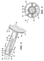
- FIG. 2 A cross-sectional view of a first embodiment of the ultrasonic acoustic cleaning apparatus 12 in accordance with the present invention is illustrated in FIG. 2 .
- FIG. 3 A cross-sectional view of the ultrasonic acoustic cleaning apparatus 12 taken along line 3-3 of FIG. 2 is illustrated in FIG. 3 .
- the ultrasonic acoustic cleaning apparatus 12 includes an ultrasonic system comprising an ultrasonic horn 40 and an ultrasonic transducer 42 for driving the ultrasonic horn 40.
- the ultrasonic acoustic cleaning apparatus 12 further includes a spray nozzle 44 for supplying an atomized spray of a cleaning solution.
- the ultrasonic horn 40, ultrasonic transducer 42, and the spray nozzle 44 are all enclosed within a vacuum cannula 46.
- the ultrasonic acoustic cleaning apparatus 12 is positioned in close proximity to the surface 14 of the print substrate 16.
- the particular distance of the ultrasonic acoustic cleaning apparatus 12 from the surface 14 of the print substrate 16 is generally application specific, and may be dependent upon many factors, including the power of the ultrasonic transducer 42, the configuration of the ultrasonic horn 40, the type of spray nozzle 44 used, the strength of the vacuum applied within the vacuum cannula 46, the material properties of the coating material 48 to be removed from the surface 14 of the print substrate 16, etc.
- the power of the ultrasonic transducer 42 is generally application specific, and may be dependent upon factors including those presented above.
- the power of the ultrasonic transducer 42 may be in the range of about 1500 to 6000 watts. Other power values are also possible.
- the ultrasonic transducer 42 is supported within a housing 50 along a center of the vacuum cannula 46.
- the housing 50 is attached to an inner surface of the vacuum cannula 46 by a plurality of radially extending ribs 52.
- Power/control lines 54 of the ultrasonic transducer 42 extend out of the end 56 of the vacuum cannula 46 into a hose 58 through connector 60.
- a vacuum is supplied to a vacuum port 62 within the vacuum cannula 46 by a vacuum source (not shown).
- the vacuum source is coupled to the vacuum port 62 via hose 64 and connector 66.
- Cleaning solution is supplied to the spray nozzle 44 through a supply line 68.
- the supply line 68 extends through connector 60 into hose 58.
- the ultrasonic acoustic cleaning apparatus 12 is used to clean the surface 14 of the print substrate 16 after a print run and before reapplication of the coating material 48.
- a cleaning solution is directed onto the surface 14 of the print substrate 16 through spray nozzle 44 as the plate cylinder 18 rotates as indicated by directional arrow 72 past the vacuum cannula 46.
- the surface 14 After passing under the spray nozzle 44, the surface 14 subsequently rotates under the ultrasonic horn 40, which operates to remove the coating material 48 from the surface 14. As rotation of the press-cylinder continues, all debris from the cleaning process is collected and removed through the vacuum port 62.
- the ultrasonic acoustic cleaning apparatus 12 is displaced by a drive system D3 ( Fig. 1 ) axially along the plate cylinder 18 in a "slow-scan" direction as indicated by directional arrow 70 (see FIGS. 1 and 3 ).
- the print substrate 16 may be "refreshed” if necessary using a water rinse.
- a solvent-type cleaning solution was applied on the surface of the print substrate. After waiting some dwell period to allow the solvent to sufficiently soften the bonded polymer of the coating material, the coating material was removed by mechanical means (e.g., scrubbed with a brush or roller). The resultant waste material was then rinsed from the print substrate, and the substrate was dried using hot air.
- the cleaning solution of the present invention is not only used for its inherent solvent cleaning/softening function, but also as a coupling agent for the ultrasonic horn 40. In particular, when sprayed as a mist between the ultrasonic horn 40 and the print substrate 16, the atomized cleaning solution couples and focuses the energy of the ultrasonic horn 40 to the coating material 48 on the surface 14 of the print substrate 16.
- the focused energy promotes acoustic cavitation.
- This cavitation is the result of excitation at the molecular level of the coupling liquid (i.e., the cleaning solution) on and at the coating material 48.
- the excitation causes friction and thus turns the acoustic energy to heat.
- the heat causes the water molecules of the cleaning solution to move apart forming gas or steam which condenses on colder surrounding areas, thereby causing voids to develop.
- Adjacent molecules fill in the voids, violently sending shock waves through the coating material 48 and initiating a series of subsequent chain reactions and surface implosions.
- This causes the coating material 48 (e.g., polymer) to be instantly softened and "blasted" from the surface 14 of the print substrate 16.
- the softening characteristic of the solvent is so enhanced by cavitation that the cleaning of the surface 14 of the print substrate 16 is immediate and complete so as not to require additional mechanical cleaning.
- the cleaning solution is an aqueous-based solvent-type cleaning solution that is specifically formulated to soften the coating material 48 on the surface 14 of the print substrate 16.
- this type of cleaning solution when sprayed onto the coating material, also serves to focus the energy of the ultrasonic horn 40 onto the coating material 48 to initiate and sustain acoustic cavitation.
- any suitable type of atomized aqueous spray including plain water, may be used to couple and focus the energy of the ultrasonic horn 40 onto the coating material 48 on the surface 14.
- the choice of cleaning solution is dependent on many different factors, including, for example, the material characteristics of the coating material 48, the power of the ultrasonic transducer 42, etc.
- a vacuum is drawn within the vacuum port 62 of the vacuum cannula 46.
- the vacuum removes any excess cleaning solution and all of the debris resulting from the cleaning process from the surface 14 of the print substrate 16. This leaves the surface 14 clean and dry.
- the removed materials are subsequently transferred through the hose 64 to entrainment separators (not shown) for collection and disposal.
- the ultrasonic acoustic cleaning apparatus 12 of the present invention may be used as a stand-alone device as shown in FIG. 1 , or may be coupled to other components of the printing press 10.
- the ultrasonic acoustic cleaning apparatus 12 may be coupled to the imaging system 28.
- a separate drive system for the ultrasonic acoustic cleaning apparatus 12 is not required; displacement of the ultrasonic acoustic cleaning apparatus 12 is provided by the drive system D2 of the imaging system 28 (or vice-versa).
- This configuration may be useful, for example, when access to the plate cylinder 18 in the printing press 10 is limited.
- the ultrasonic acoustic cleaning apparatus 12 could also be coupled to the spraying system 24. In this case, displacement of the ultrasonic acoustic cleaning apparatus 12 is provided by the drive system D1 of the spraying system 24 (or vice-versa).
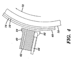
- FIG. 4 Another embodiment of an ultrasonic acoustic cleaning apparatus 12 is illustrated in FIG. 4 .
- the vacuum port 62 and the spray nozzle 44 are incorporated within the body of the ultrasonic horn 40. This provides a more compact system.
- cleaning solution is introduced by the spray nozzle 44 at the leading end 82 of the ultrasonic horn 40 where cavitation begins.
- the coating material 48 is loosened and removed from the surface 14 of the print substrate 16 by the cavitation process. Any remaining cleaning solution and debris from the cleaning process is sucked from the surface 14 into the vacuum port 62 as the surface 14 passes under the trailing end 84 of the ultrasonic horn 40.
- the ultrasonic acoustic cleaning apparatus of the present invention may be used to clean a coating material that has been applied directly to a surface of the plate cylinder.
- Such modifications and variations that may be apparent to a person skilled in the art may be included within the scope of this invention as defined in the appended claims.
Landscapes
- Inking, Control Or Cleaning Of Printing Machines (AREA)
- Application Of Or Painting With Fluid Materials (AREA)
- Manufacturing Of Printed Wiring (AREA)
- Manufacture Or Reproduction Of Printing Formes (AREA)
- Rotary Presses (AREA)
- Printing Plates And Materials Therefor (AREA)
Claims (11)
- Un procédé pour le nettoyage d'un substrat d'impression (16) calé sur un cylindre porte-plaque (18), ledit procédé comprenant les étapes ci-après :- l'application d'une solution de nettoyage sur une surface (14) du substrat d'impression (16),- la rotation du cylindre porte-plaque (18), provoquant ainsi l'acheminement du substrat d'impression (12) sous un appareil de nettoyage acoustique par ultrasons (12) afin d'éliminer un matériau de couchage (48) de la surface (14) du substrat d'impression (16),
sans qu'un nettoyage mécanique supplémentaire soit nécessaire, et- l'enlèvement du matériau de couchage éliminé (48) et de la solution de nettoyage du substrat d'impression (16) en utilisant un système d'aspiration sous vide (46, 62, 64). - Procédé selon la revendication 1, comprenant en outre l'étape consistant à :appliquer de nouveau du matériau de couchage (48) sur la surface (14) du substrat d'impression (16) après la fin des étapes d'application, de rotation et d'enlèvement.
- Procédé selon l'une quelconque des revendications précédentes, caractérisé en ce que le matériau de couchage (48) comprend une plaque d'impression lithographique.
- Procédé selon la revendication 3, caractérisé en ce que le cylindre porte-plaque (18) occupe une zone d'une presse à imprimer, ledit procédé consistant en outre à exécuter les étapes de l'application, de la rotation et de l'enlèvement après la fin d'un cycle d'impression effectué sur la presse à imprimer en utilisant la plaque d'impression lithographique.
- Procédé selon la revendication 4, consistant en outre à insoler le matériau de couchage (48) afin de former la plaque d'impression lithographique avant de procéder au cycle d'impression.
- Procédé selon l'une quelconque des revendications précédentes, caractérisé en ce que la solution de nettoyage est appliquée sur la surface (14) du substrat d'impression (16) à l'aide d'une buse de pulvérisation (44).
- Procédé selon la revendication 6, consistant en outre à enfermer la buse de pulvérisation (44), l'appareil de nettoyage acoustique par ultrasons (12) et un orifice d'aspiration sous vide (62) du système d'aspiration sous vide dans une canule sous vide (46).
- Procédé selon la revendication 7, consistant en outre à déplacer axialement la canule sous vide (46) le long du substrat d'impression (16) lors de la rotation du cylindre porte-plaque (18) .
- Procédé selon l'une quelconque des revendications précédentes, caractérisé en ce que l'appareil de nettoyage acoustique par ultrasons (12) comprend une sonotrode (40) et un transducteur ultrasonique (42) pilotant la sonotrode (40) et que la solution de nettoyage pulvérisée transfère l'énergie de la sonotrode (40) au matériau de couchage (48) appliqué sur le substrat d'impression (16).
- Un appareil pour le nettoyage d'un substrat d'impression (16) calé sur un cylindre porte-plaque rotatif (18), ledit appareil comprenant les éléments suivantes :- un système pour l'application d'une solution de nettoyage sur une surface (14) du substrat d'impression (16),- un appareil de nettoyage acoustique par ultrasons (12) servant à éliminer un matériau de couchage (48) de la surface (14) du substrat d'impression (16),
sans qu'un nettoyage mécanique supplémentaire soit nécessaire, et- un système d'aspiration sous vide (46, 62, 64) servant à enlever le matériau de couchage éliminé (48) et de la solution de nettoyage du substrat d'impression (16). - Une presse à imprimer (10) comprenant les éléments suivantes :- l'appareil de nettoyage selon la revendication 10, et- un système de formation d'image (28) servant à exposer le matériau de couchage (48) afin d'y former une image.
Applications Claiming Priority (2)
| Application Number | Priority Date | Filing Date | Title |
|---|---|---|---|
| US10/095,335 US6810807B2 (en) | 2001-03-12 | 2002-03-11 | Method and apparatus for cleaning coating materials from a substrate |
| US95335 | 2002-03-11 |
Publications (3)
| Publication Number | Publication Date |
|---|---|
| EP1346827A2 EP1346827A2 (fr) | 2003-09-24 |
| EP1346827A3 EP1346827A3 (fr) | 2004-02-04 |
| EP1346827B1 true EP1346827B1 (fr) | 2008-11-05 |
Family
ID=27788235
Family Applications (1)
| Application Number | Title | Priority Date | Filing Date |
|---|---|---|---|
| EP03100613A Expired - Lifetime EP1346827B1 (fr) | 2002-03-11 | 2003-03-11 | Méthode et appareil pour nettoyer des matériaux enduisant d'un substrat |
Country Status (4)
| Country | Link |
|---|---|
| US (1) | US6810807B2 (fr) |
| EP (1) | EP1346827B1 (fr) |
| JP (1) | JP2003266648A (fr) |
| DE (1) | DE60324493D1 (fr) |
Families Citing this family (9)
| Publication number | Priority date | Publication date | Assignee | Title |
|---|---|---|---|---|
| JP2004322511A (ja) * | 2003-04-25 | 2004-11-18 | Konica Minolta Medical & Graphic Inc | 印刷方法 |
| ITMI20031131A1 (it) * | 2003-06-05 | 2004-12-06 | Omet Srl | Metodo e dispositivo per la pulizia di un cilindro di |
| DE10360011A1 (de) * | 2003-12-19 | 2005-07-21 | Man Roland Druckmaschinen Ag | Vorrichtung zum Reinigen von Walzen, Zylindern und Druckformen |
| ITFI20040051A1 (it) * | 2004-03-04 | 2004-06-04 | Perini Fabio | Dispositivo, metodo e kit per la pulizia dei rulli in macchine da stampa |
| US20050223926A1 (en) * | 2004-04-08 | 2005-10-13 | Michael Baeten | Apparatus for cleaning a rotating cylinder |
| DE102004047456A1 (de) * | 2004-09-30 | 2006-08-03 | Man Roland Druckmaschinen Ag | Verfahren und Vorrichtung zum Auftragen eines Mediums auf eine Druckform |
| TWI420616B (zh) * | 2010-08-05 | 2013-12-21 | Au Optronics Corp | 基板清洗機台與基板清洗方法 |
| US10688536B2 (en) | 2014-02-24 | 2020-06-23 | The Boeing Company | System and method for surface cleaning |
| US10343193B2 (en) | 2014-02-24 | 2019-07-09 | The Boeing Company | System and method for surface cleaning |
Family Cites Families (9)
| Publication number | Priority date | Publication date | Assignee | Title |
|---|---|---|---|---|
| US5148746A (en) * | 1988-08-19 | 1992-09-22 | Presstek, Inc. | Print-head and plate-cleaning assembly |
| US5240506A (en) * | 1989-03-27 | 1993-08-31 | Sonicor Instrument Corporation | Process for the ultrasonic cleaning of a printing cylinder |
| DK83193A (da) * | 1993-07-09 | 1995-01-10 | Tresu A S Maskinfabriken | Fremgangsmåde og apparat til rensning af overfladen på en valse |
| US5574485A (en) * | 1994-10-13 | 1996-11-12 | Xerox Corporation | Ultrasonic liquid wiper for ink jet printhead maintenance |
| DE29507416U1 (de) * | 1995-05-04 | 1995-07-06 | MAN Roland Druckmaschinen AG, 63075 Offenbach | Einrichtung zum Reinigen von farbübertragenden Zylindern |
| US5713287A (en) * | 1995-05-11 | 1998-02-03 | Creo Products Inc. | Direct-to-Press imaging method using surface modification of a single layer coating |
| US6280014B1 (en) * | 1999-12-14 | 2001-08-28 | Eastman Kodak Company | Cleaning mechanism for inkjet print head with fixed gutter |
| JP2001277466A (ja) * | 2000-03-29 | 2001-10-09 | Fuji Photo Film Co Ltd | 機上描画平版印刷方法及び機上描画平版印刷装置 |
| EP1228871A1 (fr) | 2001-02-06 | 2002-08-07 | Agfa-Gevaert | Appareil de nettoyage d'une surface |
-
2002
- 2002-03-11 US US10/095,335 patent/US6810807B2/en not_active Expired - Fee Related
-
2003
- 2003-03-04 JP JP2003056918A patent/JP2003266648A/ja active Pending
- 2003-03-11 DE DE60324493T patent/DE60324493D1/de not_active Expired - Lifetime
- 2003-03-11 EP EP03100613A patent/EP1346827B1/fr not_active Expired - Lifetime
Also Published As
| Publication number | Publication date |
|---|---|
| JP2003266648A (ja) | 2003-09-24 |
| US6810807B2 (en) | 2004-11-02 |
| EP1346827A2 (fr) | 2003-09-24 |
| EP1346827A3 (fr) | 2004-02-04 |
| DE60324493D1 (de) | 2008-12-18 |
| US20020124754A1 (en) | 2002-09-12 |
Similar Documents
| Publication | Publication Date | Title |
|---|---|---|
| EP1344645B1 (fr) | Procédé et dispositif pour appliquer avec ultrasons un matériau de revêtement sur un substrat | |
| CN1642738A (zh) | 可变数据平版印刷设备和方法 | |
| EP1346827B1 (fr) | Méthode et appareil pour nettoyer des matériaux enduisant d'un substrat | |
| US6408755B1 (en) | Method for erasing a lithographic printing master | |
| EP1118472B1 (fr) | Procédé d'impression lithographique avec un support de plaque d'impression réutilisable | |
| US6487970B2 (en) | Method of lithographic printing with a reusable substrate | |
| EP1118471B1 (fr) | Méthode pour l'impression lithographique utilisant un support à surface réutilisable | |
| EP1118470B1 (fr) | Méthode pour l'impression lithographique utilisant un support à surface réutilisable | |
| US20050066830A1 (en) | Image forming device for planographic printing plates | |
| JP2002316485A (ja) | 表面をクリーニングする装置 | |
| US6694881B2 (en) | Direct-to-plate lithographic printing method using automatic plate-coating and cleaning | |
| US6460458B2 (en) | Method of planographic printing with a reusable substrate | |
| EP1080942B2 (fr) | Méthode de régénération d'une plaque d'impression lithographique | |
| US20030113437A1 (en) | Metered application of imageable media | |
| EP1142706B1 (fr) | Procédé d'impression lithographique dite "direct-to-plate", avec revêtement et nettoyage automatique des plaques d'impression | |
| JP2000326652A (ja) | 平版印刷マスターの作製方法 | |
| EP1118473A1 (fr) | Appareil pour le revêtement et le nettoyage automatiques des plaques d'impression lithographique | |
| JP2002355942A (ja) | バルブジェットにより像記録層をコーティングする方法 | |
| JP2002219303A (ja) | 再使用可能な基質を用いる平版印刷方法 | |
| US20030017418A1 (en) | Method of processing a lithographic printing plate precursor | |
| JP2002160344A (ja) | 再使用可能な基質を用いる平版印刷方法 | |
| CN1608844A (zh) | 用可重复使用的铝载体进行平版印刷的方法 | |
| JP2002240232A (ja) | 再使用可能な基質を用いる平版印刷方法 | |
| EP1271250A2 (fr) | Procédé pour le développement d un précurseur d une plaque d impression planographique | |
| JP2002200730A (ja) | 自動的な版コーテイングおよび版クリーニング用の装置 |
Legal Events
| Date | Code | Title | Description |
|---|---|---|---|
| PUAI | Public reference made under article 153(3) epc to a published international application that has entered the european phase |
Free format text: ORIGINAL CODE: 0009012 |
|
| AK | Designated contracting states |
Kind code of ref document: A2 Designated state(s): AT BE BG CH CY CZ DE DK EE ES FI FR GB GR HU IE IT LI LU MC NL PT SE SI SK TR |
|
| AX | Request for extension of the european patent |
Extension state: AL LT LV MK RO |
|
| PUAL | Search report despatched |
Free format text: ORIGINAL CODE: 0009013 |
|
| AK | Designated contracting states |
Kind code of ref document: A3 Designated state(s): AT BE BG CH CY CZ DE DK EE ES FI FR GB GR HU IE IT LI LU MC NL PT SE SI SK TR |
|
| AX | Request for extension of the european patent |
Extension state: AL LT LV MK RO |
|
| 17P | Request for examination filed |
Effective date: 20040804 |
|
| AKX | Designation fees paid |
Designated state(s): DE FR GB |
|
| 17Q | First examination report despatched |
Effective date: 20061220 |
|
| GRAP | Despatch of communication of intention to grant a patent |
Free format text: ORIGINAL CODE: EPIDOSNIGR1 |
|
| GRAS | Grant fee paid |
Free format text: ORIGINAL CODE: EPIDOSNIGR3 |
|
| GRAA | (expected) grant |
Free format text: ORIGINAL CODE: 0009210 |
|
| AK | Designated contracting states |
Kind code of ref document: B1 Designated state(s): DE FR GB |
|
| REG | Reference to a national code |
Ref country code: GB Ref legal event code: FG4D |
|
| REF | Corresponds to: |
Ref document number: 60324493 Country of ref document: DE Date of ref document: 20081218 Kind code of ref document: P |
|
| PLBE | No opposition filed within time limit |
Free format text: ORIGINAL CODE: 0009261 |
|
| STAA | Information on the status of an ep patent application or granted ep patent |
Free format text: STATUS: NO OPPOSITION FILED WITHIN TIME LIMIT |
|
| 26N | No opposition filed |
Effective date: 20090806 |
|
| PGFP | Annual fee paid to national office [announced via postgrant information from national office to epo] |
Ref country code: FR Payment date: 20110217 Year of fee payment: 9 |
|
| PGFP | Annual fee paid to national office [announced via postgrant information from national office to epo] |
Ref country code: DE Payment date: 20110211 Year of fee payment: 9 Ref country code: GB Payment date: 20110215 Year of fee payment: 9 |
|
| GBPC | Gb: european patent ceased through non-payment of renewal fee |
Effective date: 20120311 |
|
| REG | Reference to a national code |
Ref country code: FR Ref legal event code: ST Effective date: 20121130 |
|
| REG | Reference to a national code |
Ref country code: DE Ref legal event code: R119 Ref document number: 60324493 Country of ref document: DE Effective date: 20121002 |
|
| PG25 | Lapsed in a contracting state [announced via postgrant information from national office to epo] |
Ref country code: GB Free format text: LAPSE BECAUSE OF NON-PAYMENT OF DUE FEES Effective date: 20120311 Ref country code: FR Free format text: LAPSE BECAUSE OF NON-PAYMENT OF DUE FEES Effective date: 20120402 |
|
| PG25 | Lapsed in a contracting state [announced via postgrant information from national office to epo] |
Ref country code: DE Free format text: LAPSE BECAUSE OF NON-PAYMENT OF DUE FEES Effective date: 20121002 |