EP1346846A2 - Manchon pour l'impression flexographique - Google Patents
Manchon pour l'impression flexographique Download PDFInfo
- Publication number
- EP1346846A2 EP1346846A2 EP03004728A EP03004728A EP1346846A2 EP 1346846 A2 EP1346846 A2 EP 1346846A2 EP 03004728 A EP03004728 A EP 03004728A EP 03004728 A EP03004728 A EP 03004728A EP 1346846 A2 EP1346846 A2 EP 1346846A2
- Authority
- EP
- European Patent Office
- Prior art keywords
- sleeve
- sleeve according
- conductive
- sleeve body
- printing
- Prior art date
- Legal status (The legal status is an assumption and is not a legal conclusion. Google has not performed a legal analysis and makes no representation as to the accuracy of the status listed.)
- Granted
Links
- 239000012811 non-conductive material Substances 0.000 claims abstract description 12
- 239000004918 carbon fiber reinforced polymer Substances 0.000 claims description 9
- 239000002184 metal Substances 0.000 claims description 7
- 229910052751 metal Inorganic materials 0.000 claims description 7
- 239000011152 fibreglass Substances 0.000 claims description 6
- 239000004033 plastic Substances 0.000 claims description 5
- 229920003023 plastic Polymers 0.000 claims description 5
- 239000011248 coating agent Substances 0.000 claims description 4
- 238000000576 coating method Methods 0.000 claims description 4
- 239000004020 conductor Substances 0.000 claims description 4
- 238000007599 discharging Methods 0.000 claims description 3
- 239000004922 lacquer Substances 0.000 claims description 3
- 239000002131 composite material Substances 0.000 claims description 2
- 239000011159 matrix material Substances 0.000 claims description 2
- 229920002635 polyurethane Polymers 0.000 claims description 2
- 239000004814 polyurethane Substances 0.000 claims description 2
- 239000002904 solvent Substances 0.000 abstract description 5
- 238000004200 deflagration Methods 0.000 abstract description 3
- 239000000976 ink Substances 0.000 description 5
- 239000000463 material Substances 0.000 description 5
- 239000000758 substrate Substances 0.000 description 4
- 241000209035 Ilex Species 0.000 description 3
- 239000006260 foam Substances 0.000 description 3
- 239000000126 substance Substances 0.000 description 3
- 230000004323 axial length Effects 0.000 description 2
- 238000007600 charging Methods 0.000 description 2
- 238000007786 electrostatic charging Methods 0.000 description 2
- 230000007613 environmental effect Effects 0.000 description 2
- 239000011888 foil Substances 0.000 description 2
- 238000000034 method Methods 0.000 description 2
- 239000003973 paint Substances 0.000 description 2
- 229920000049 Carbon (fiber) Polymers 0.000 description 1
- RYGMFSIKBFXOCR-UHFFFAOYSA-N Copper Chemical compound [Cu] RYGMFSIKBFXOCR-UHFFFAOYSA-N 0.000 description 1
- AEMRFAOFKBGASW-UHFFFAOYSA-N Glycolic acid Chemical compound OCC(O)=O AEMRFAOFKBGASW-UHFFFAOYSA-N 0.000 description 1
- 229910000831 Steel Inorganic materials 0.000 description 1
- 230000006978 adaptation Effects 0.000 description 1
- 150000001298 alcohols Chemical class 0.000 description 1
- 230000000903 blocking effect Effects 0.000 description 1
- 239000006229 carbon black Substances 0.000 description 1
- 239000004917 carbon fiber Substances 0.000 description 1
- -1 carboxylic acid ethers Chemical class 0.000 description 1
- 238000005266 casting Methods 0.000 description 1
- 239000003086 colorant Substances 0.000 description 1
- 150000001875 compounds Chemical class 0.000 description 1
- 238000010276 construction Methods 0.000 description 1
- 229910052802 copper Inorganic materials 0.000 description 1
- 239000010949 copper Substances 0.000 description 1
- 238000009795 derivation Methods 0.000 description 1
- 229920001971 elastomer Polymers 0.000 description 1
- 230000002349 favourable effect Effects 0.000 description 1
- 239000000835 fiber Substances 0.000 description 1
- 239000011151 fibre-reinforced plastic Substances 0.000 description 1
- 238000009413 insulation Methods 0.000 description 1
- 238000004519 manufacturing process Methods 0.000 description 1
- 239000002245 particle Substances 0.000 description 1
- 239000000049 pigment Substances 0.000 description 1
- 230000003389 potentiating effect Effects 0.000 description 1
- 230000001681 protective effect Effects 0.000 description 1
- 229910052709 silver Inorganic materials 0.000 description 1
- 239000004332 silver Substances 0.000 description 1
- 239000010959 steel Substances 0.000 description 1
- 210000002435 tendon Anatomy 0.000 description 1
- 239000002966 varnish Substances 0.000 description 1
Images
Classifications
-
- B—PERFORMING OPERATIONS; TRANSPORTING
- B41—PRINTING; LINING MACHINES; TYPEWRITERS; STAMPS
- B41C—PROCESSES FOR THE MANUFACTURE OR REPRODUCTION OF PRINTING SURFACES
- B41C1/00—Forme preparation
- B41C1/18—Curved printing formes or printing cylinders
- B41C1/182—Sleeves; Endless belts
-
- B—PERFORMING OPERATIONS; TRANSPORTING
- B41—PRINTING; LINING MACHINES; TYPEWRITERS; STAMPS
- B41F—PRINTING MACHINES OR PRESSES
- B41F27/00—Devices for attaching printing elements or formes to supports
- B41F27/10—Devices for attaching printing elements or formes to supports for attaching non-deformable curved printing formes to forme cylinders
- B41F27/105—Devices for attaching printing elements or formes to supports for attaching non-deformable curved printing formes to forme cylinders for attaching cylindrical printing formes
-
- B—PERFORMING OPERATIONS; TRANSPORTING
- B41—PRINTING; LINING MACHINES; TYPEWRITERS; STAMPS
- B41F—PRINTING MACHINES OR PRESSES
- B41F30/00—Devices for attaching coverings or make-ready devices; Guiding devices for coverings
-
- B—PERFORMING OPERATIONS; TRANSPORTING
- B41—PRINTING; LINING MACHINES; TYPEWRITERS; STAMPS
- B41F—PRINTING MACHINES OR PRESSES
- B41F5/00—Rotary letterpress machines
- B41F5/24—Rotary letterpress machines for flexographic printing
-
- B—PERFORMING OPERATIONS; TRANSPORTING
- B41—PRINTING; LINING MACHINES; TYPEWRITERS; STAMPS
- B41N—PRINTING PLATES OR FOILS; MATERIALS FOR SURFACES USED IN PRINTING MACHINES FOR PRINTING, INKING, DAMPING, OR THE LIKE; PREPARING SUCH SURFACES FOR USE AND CONSERVING THEM
- B41N1/00—Printing plates or foils; Materials therefor
- B41N1/16—Curved printing plates, especially cylinders
-
- B—PERFORMING OPERATIONS; TRANSPORTING
- B41—PRINTING; LINING MACHINES; TYPEWRITERS; STAMPS
- B41C—PROCESSES FOR THE MANUFACTURE OR REPRODUCTION OF PRINTING SURFACES
- B41C1/00—Forme preparation
- B41C1/18—Curved printing formes or printing cylinders
-
- B—PERFORMING OPERATIONS; TRANSPORTING
- B41—PRINTING; LINING MACHINES; TYPEWRITERS; STAMPS
- B41N—PRINTING PLATES OR FOILS; MATERIALS FOR SURFACES USED IN PRINTING MACHINES FOR PRINTING, INKING, DAMPING, OR THE LIKE; PREPARING SUCH SURFACES FOR USE AND CONSERVING THEM
- B41N2207/00—Location or type of the layers in shells for rollers of printing machines
- B41N2207/02—Top layers
-
- B—PERFORMING OPERATIONS; TRANSPORTING
- B41—PRINTING; LINING MACHINES; TYPEWRITERS; STAMPS
- B41N—PRINTING PLATES OR FOILS; MATERIALS FOR SURFACES USED IN PRINTING MACHINES FOR PRINTING, INKING, DAMPING, OR THE LIKE; PREPARING SUCH SURFACES FOR USE AND CONSERVING THEM
- B41N7/00—Shells for rollers of printing machines
-
- B—PERFORMING OPERATIONS; TRANSPORTING
- B41—PRINTING; LINING MACHINES; TYPEWRITERS; STAMPS
- B41P—INDEXING SCHEME RELATING TO PRINTING, LINING MACHINES, TYPEWRITERS, AND TO STAMPS
- B41P2200/00—Printing processes
- B41P2200/10—Relief printing
- B41P2200/12—Flexographic printing
Definitions
- the invention relates to a sleeve for flexographic printing, with a Sleeve body from at least partially electrically not conductive material with its inside on a as Air cylinder designed, electrically on the outer wall of the roller conductive support roller of a printing press is mountable and in the assembled state at least one contact zone with the support roller having.
- sleeves for flexographic printing with wall thicknesses of more at least one compressible soft foam layer is also considered to be 5 mm provided to despite the considerable wall thickness the expansion of the sleeve body during assembly or disassembly to ensure.
- sleeve variants at which the entire wall structure is made of compressible material is. After completing the assembly and switching off the Compressed air sits the sleeve with a press fit on the outer wall of the roller the support roller and is held on it in a rotationally fixed manner.
- Electrostatic charges can occur in different areas of the printing press. You can e.g. between the substrate to be printed, e.g. a film and the printing form due to the lifting movement and caused by excessive charging of the paint. If none appropriate protective measures are taken, potentiate themselves with an increasing number of printing units, the electrostatic Charges as the substrate to be printed progresses in the machine, so that in the machine direction rear printing units dangerous discharges into the ink fountains and or can occur in the chambered doctor blade.
- Suitable electrostatic charges can be Adaptation of the environmental conditions, especially compliance an air humidity of about 65% and / or ionization of the Limit air in the work area.
- the object of the invention is to provide a sleeve for flexographic printing create the one hand at least partially electric non-conductive material, so that their assembly after Air cushion principle can be done, and the same time minimizes the problem of electrostatic charges or avoids.
- the sleeves made of (partially) non-conductive material to give electrically conductive structure, through which the inevitable electrostatic charges directly over the carrier roller be derived so that the charge of each Sleeves or application rollers in the printing unit do not reach a size can be used for a discharge, ignition or deflagration the solvent is sufficient, and not to subsequent ones Printing units is passed on.
- the sleeve is provided with an electrically conductive surface is electrical with the contact zone via at least one conductive element arranged in the sleeve body for Dissipation of electrostatic charges in the outer wall of the roll the support roller is connected.
- the electrically conductive surface is the sleeve and therefore the sleeve for flexographic printing over the element arranged in the sleeve body and the roller outer wall the carrier roller is grounded.
- the sleeves according to the invention get an electrically conductive structure without losing their weight increases. The low weight desired by the user can also be achieved or maintained with the sleeves according to the invention become.
- electrically conductive should refer in particular to substances or materials whose specific resistance is less than 10 4 ⁇ m. Since it is important for the invention to discharge the electrostatic charge, electrically conductive substances or materials may also include those which are electrically conductive and whose specific resistance is between 10 4 ⁇ m and approximately 10 9 ⁇ m. Accordingly, those substances and materials whose specific resistance is greater than 10 4 ⁇ m or which are neither conductive nor dissipative are not conductive.
- the electrically conductive surface of the sleeve can be different Wise men are formed or applied.
- a varnish can be mixed, for example with conductive particles such as carbon black or with metal pigments such as silver or copper and the like. the desired conductivity receive.
- the plastic layer can in particular also made of glass fiber reinforced plastic (GRP) conductive matrix or from one due to the carbon fibers conductive carbon fiber reinforced plastic (CFRP).
- GRP glass fiber reinforced plastic
- CFRP carbon fiber reinforced plastic
- the sleeve body can on its outer surface with a metallic coating forming the surface of the sleeve be provided. It is useful for this, for example to steam the sleeve body with suitable metal. Either the application of the conductive lacquer as well as the application of a metallic coating allow existing ones Retrofit sleeves for flexographic printing and in a sleeve service should subsequently be made conductive.
- the electrical conductivity of the sleeve can alternatively also can be achieved in that the sleeve body made of a composite material with electrically conductive, a braid of Inserts forming connecting elements.
- the sleeve body can be made from a metal fiber or carbon fiber reinforced plastic (CFRP), care must be taken when manufacturing the sleeve, that the deposits or fibers are not only axial, but also extend radially from the contact surface to the surface.
- CFRP carbon fiber reinforced plastic
- a sleeve made entirely of CFRP is only small Wall thicknesses up to 5 mm can be installed. With larger wall thicknesses is usually already to widen the sleeve for assembly to ensure or disassembly, the sleeve body with at least a layer of non-conductive compressible material Mistake.
- the invention provides that the layer of non-conductive material from the Element for dissipating electrostatic charges penetrated is.
- a sleeve with a non-conductive, cylindrical layer or intermediate layer is the element in a radially extending Recess arranged in the sleeve body.
- the recess can here are formed in particular by a radial bore.
- the discharge element for electrostatic charging not the compressibility of the layer of non-conductive material is disabled in this embodiment is special favorable if the element change its length in the radial direction can and independently after assembly on the electrical Connection sets the necessary length.
- This can preferably be achieved in that the element spring-loaded contact body.
- the contact body is arranged such that it protrudes beyond the inside of the sleeve body before assembly. With the spring, the contact body is thus in the direction pre-tensioned on the inside of the sleeve, i.e. in the assembled state pressed against the outer roller wall of the support roller, so that the electrically conductive connection between the conductive Surface of the sleeve and the electrically conductive support roller is guaranteed.
- the contact body of a Ball is formed or at least a spherical contact end having.
- an electrically conductive housing e.g. made of metal have, which receives the spring and the contact body and with its case bottom with the conductive surface connected is.
- a sleeve body can be made of this non-conductive material subsequently with at least one radial Through hole are provided in which an element for electrostatic discharge before applying the conductive Surface is used.
- the item can be in the Through hole or the recess in particular screwed or be glued in.
- Recess or through hole on the inside of the sleeve body is lowered so that during assembly or disassembly the sleeve between the inside of the sleeve body and air cushions created by the support roller do not move or loosen the element or its housing can.
- the contact zone does not necessarily have to be on the inside of the Sleeve lying.
- Most of the support rollers have a centering projection for the register setting on which the sleeve is centered with a centering recess during assembly.
- the contact zone can therefore Be part of the centering recess, with the other
- the advantage is that the compressibility of the intermediate layer is not affected.
- To contact the contact zone to ensure with the centering projection, in the centering recess is provided with spring-loaded contact elements become.
- the sleeve body can be used as an element for the electrostatic discharge at least one tendon made of conductive Material, in particular made of metal.
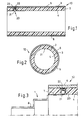
- reference number 10 is a sleeve for the Flexographic printing, which is based on the air cushion principle on a shown exclusively in Fig. 3, as an air cylinder Carrying roller 1 executed a flexographic printing machine, not shown is mountable.
- the sleeve 10 has a cylindrical Sleeve body 2 with a multilayer structure. With the sleeve 10 can in particular be a so-called build-up sleeve act.
- the sleeve body 10 can e.g. a base sleeve have glass fiber reinforced plastic with several Layers such as compressible soft foam, LD casting compound, Hard foam and a hard coat or soft coat top layer is. The selection of the top layer then depends the type and attachment of those used for printing, not illustrated printing forms.
- the sleeve body 2 either completely made of electrically non-conductive material, or the sleeve body 2 has a continuous intermediate layer made of electrically non-conductive material, the one Insulation between the outside 3 of the sleeve body 2 and its inside 4 causes.
- a layer 5 of electrical according to the invention conductive material applied. With layer 5 it can e.g. a vapor-deposited metal coating or one Act as a conductive lacquer. Due to the layer 5, the sleeve 10 over the entire circumference and its entire axial length electrically conductive surface 6.
- the sleeve body 2 there is at least one with reference numerals 20 designated element for discharging electrostatic Charges from the surface 6 of the sleeve 10 to the inside 4 provided.
- the element 20 is in a radial bore 23 arranged in the sleeve body 2, which on the inside 4 of the Sleeve body 2 is open and to the outside of the electrical conductive layer 5 is covered.
- Element 20 comprises a contact body shown here as ball 21, with a spring 22 in the direction of the inside 4 of the adapter sleeve is biased. Ball 21 and spring 22, both are electrically conductive, are not shown in a further arranged electrically conductive housing, which in the radial bore 23 is inserted.
- the housing and the associated radial bore 23 are designed such that the ball 21st by applying a radial force completely in can immerse the sleeve body 2. This radial force arises inevitably after the assembly of the sleeve 10 the support roller 1, as shown in FIG. 3.
- the end collar of the housing is preferably arranged in such a way that it is not up to the inside 4 of the sleeve body 2nd zoom ranges. Furthermore, the through hole 23 with a Countersink or step to be provided during sleeve assembly on the support roller 1 a loosening or moving the element 20 to prevent by the air cushion.
- Fig. 3 shows the sleeve 10 in the assembled state on the support roller 1. Since the inside 4 of the sleeve 10 and the roller outer wall 7 of the support roller 1 are cylindrical, arises from the full axial length a contact zone between sleeve 10 and Carrier roller 1. The air system of the carrier roller 1 is not shown. As can be clearly seen in FIG. 3, the ball 21 dips completely into the radial bore 23, but is by means of the spring 22 pressed against the roller outer wall 7 of the support roller 1. Electrostatic charges are on the surface 6 or the layer 5, the spring 22 and the ball 23 for Outer wall 7 of the support roller 1 forwarded and from there on the jacket of the support roller 1, as symbolic with the line 8 in Fig. 3 clarified, derived from all printing units.
- the embodiment shown in the figures is only an example and is intended to protect the scope of the registered invention not restrict.
- the invention can be applied to new sleeves be realized.
- the element for discharging electrostatic Charges can also be added to existing ones Sleeves made of non-conductive material can be installed. From the idea of the invention therefore also includes a method with which sleeves can subsequently be made conductive, by covering the outside with an electrically conductive layer is provided and an element is installed in the sleeve body which is the electrically conductive connection between the Guaranteed inside of the sleeve and its surface.
- the invention is also not limited to that the sleeve is arranged directly on the air cylinder. Therefore, are intended to fall within the scope of the appended claims also fall in embodiments in which the sleeve Intermediate layer of a so-called adapter sleeve on the air cylinder a printing press is mountable.
- the adapter sleeve is electrical conductive and the element is at the contact zone between the inside of the sleeve and the outside of the adapter sleeve, or the adapter sleeve is not electrically conductive and the element for dissipating electrostatic charges extends to the outer roller wall of the carrier roller. Further can also be in the adapter sleeve according to the invention dissipation of the electrostatic charge causing element be arranged.
Landscapes
- Engineering & Computer Science (AREA)
- Manufacturing & Machinery (AREA)
- Mechanical Engineering (AREA)
- Printing Plates And Materials Therefor (AREA)
- Rolls And Other Rotary Bodies (AREA)
- Elimination Of Static Electricity (AREA)
Applications Claiming Priority (4)
| Application Number | Priority Date | Filing Date | Title |
|---|---|---|---|
| DE20204412U | 2002-03-19 | ||
| DE20204412U DE20204412U1 (de) | 2002-03-19 | 2002-03-19 | Hülse für den Flexodruck |
| DE10243183A DE10243183C1 (de) | 2002-03-19 | 2002-09-11 | Hülse für den Flexodruck |
| DE10243183 | 2002-09-11 |
Publications (3)
| Publication Number | Publication Date |
|---|---|
| EP1346846A2 true EP1346846A2 (fr) | 2003-09-24 |
| EP1346846A3 EP1346846A3 (fr) | 2004-09-08 |
| EP1346846B1 EP1346846B1 (fr) | 2005-08-03 |
Family
ID=27789758
Family Applications (1)
| Application Number | Title | Priority Date | Filing Date |
|---|---|---|---|
| EP03004728A Expired - Lifetime EP1346846B1 (fr) | 2002-03-19 | 2003-03-04 | Manchon pour l'impression flexographique |
Country Status (5)
| Country | Link |
|---|---|
| EP (1) | EP1346846B1 (fr) |
| JP (1) | JP2003291298A (fr) |
| AT (1) | ATE301044T1 (fr) |
| DE (1) | DE10261955A1 (fr) |
| ES (1) | ES2243820T3 (fr) |
Cited By (3)
| Publication number | Priority date | Publication date | Assignee | Title |
|---|---|---|---|---|
| WO2005067364A3 (fr) * | 2004-01-15 | 2006-10-05 | Windmoeller & Hoelscher | Cylindre pour recevoir une forme d'impression |
| WO2019115699A1 (fr) | 2017-12-13 | 2019-06-20 | Flint Group Germany Gmbh | Adaptateur à serrage pneumatique |
| EP3640031A1 (fr) | 2018-10-17 | 2020-04-22 | Flint Group Germany GmbH | Cylindre pourvu de broche mobile |
Family Cites Families (5)
| Publication number | Priority date | Publication date | Assignee | Title |
|---|---|---|---|---|
| US4493256A (en) * | 1984-02-29 | 1985-01-15 | American Roller Company | Voltage applicator for limiting charge distribution in ESA printing equipment |
| US5840386A (en) * | 1996-02-22 | 1998-11-24 | Praxair S.T. Technology, Inc. | Sleeve for a liquid transfer roll and method for producing it |
| EP0943432B1 (fr) * | 1998-02-23 | 2001-11-07 | FGM Fritz Gradert Maschinenbau GmbH & Co. KG | Cylindre d'impression avec un noyeau et une chemise glissée là-dessus |
| DE19820498C2 (de) * | 1998-05-07 | 2000-07-06 | Saueressig Gmbh & Co | Verfahren zum Herstellen einer Hülse, insbesondere für die Druckindustrie |
| DE19944136A1 (de) * | 1998-11-05 | 2000-05-11 | Sogewa Walzen Sonnwald Gmbh | Druckwalze oder Druckwalzenhülse und deren Verwendung für den Flexodruck |
-
2002
- 2002-09-11 DE DE10261955A patent/DE10261955A1/de not_active Withdrawn
-
2003
- 2003-03-04 AT AT03004728T patent/ATE301044T1/de not_active IP Right Cessation
- 2003-03-04 ES ES03004728T patent/ES2243820T3/es not_active Expired - Lifetime
- 2003-03-04 EP EP03004728A patent/EP1346846B1/fr not_active Expired - Lifetime
- 2003-03-17 JP JP2003071543A patent/JP2003291298A/ja active Pending
Cited By (5)
| Publication number | Priority date | Publication date | Assignee | Title |
|---|---|---|---|---|
| WO2005067364A3 (fr) * | 2004-01-15 | 2006-10-05 | Windmoeller & Hoelscher | Cylindre pour recevoir une forme d'impression |
| WO2019115699A1 (fr) | 2017-12-13 | 2019-06-20 | Flint Group Germany Gmbh | Adaptateur à serrage pneumatique |
| US11203197B2 (en) | 2017-12-13 | 2021-12-21 | Flint Group Germany Gmbh | Pneumatically clamping adapter sleeve |
| EP3640031A1 (fr) | 2018-10-17 | 2020-04-22 | Flint Group Germany GmbH | Cylindre pourvu de broche mobile |
| WO2020078979A1 (fr) | 2018-10-17 | 2020-04-23 | Flint Group Germany Gmbh | Cylindre à broche mobile et procédé de montage et de démontage |
Also Published As
| Publication number | Publication date |
|---|---|
| EP1346846B1 (fr) | 2005-08-03 |
| JP2003291298A (ja) | 2003-10-14 |
| ATE301044T1 (de) | 2005-08-15 |
| EP1346846A3 (fr) | 2004-09-08 |
| ES2243820T3 (es) | 2005-12-01 |
| DE10261955A1 (de) | 2003-11-13 |
Similar Documents
| Publication | Publication Date | Title |
|---|---|---|
| DE3232780A1 (de) | Farbwerk fuer offsetdruckmaschinen | |
| EP1884362B1 (fr) | Outil de transfert de feuille avec dispositif de traitement | |
| EP1034078B2 (fr) | Dispositif electrostatique pour rotogravure et flexographie | |
| EP2209630B1 (fr) | Rouleau presseur | |
| DE20204412U1 (de) | Hülse für den Flexodruck | |
| EP1346846B1 (fr) | Manchon pour l'impression flexographique | |
| DE3220926A1 (de) | Rollenrotationsdruckmaschine | |
| DE102009000445A1 (de) | Verfahren und Vorrichtung zum Beschichten und Prägen eines Bedruckstoffes in einer Verarbeitungsmaschine | |
| DE10243183C1 (de) | Hülse für den Flexodruck | |
| EP1975101B1 (fr) | Enroulement d'une bande de feuille transfert | |
| DE102007057250B4 (de) | Auftragsvorrichtung für ein Druck-/Lackwerk in einer Verarbeitungsmaschine | |
| DE102005016309B4 (de) | Bogendruckmaschine | |
| DE4421310C2 (de) | Beschichtungs- oder Farbauftragwalze | |
| EP2377686B1 (fr) | Manchon à monter sur un cylindre de machine d'impression | |
| DE3519134C1 (de) | Walze,insbesondere Farb- oder Verreiberwalze,fuer Druckmaschinen sowie deren Verwendung | |
| DE19515459C2 (de) | Gummituchzylinder | |
| WO2010089215A1 (fr) | Procédé et dispositif de façonnage d'un support d'impression dans une machine de traitement | |
| DE19516068C2 (de) | Reinigungseinrichtung für Druckwerke von Rotationsdruckmaschinen | |
| EP2222470B1 (fr) | Dispositif d'enduction équipé d'un cylindre porte-cliché et d'au moins un rouleau enducteur dans une machine de traitement | |
| DE8224875U1 (de) | Farbwerk für Offsetdruckmaschinen | |
| DE102013103712A1 (de) | Druckwerk und Gummituchplatte für ein Druckwerk | |
| DE102007010433B4 (de) | Druckwerk | |
| EP0943432A1 (fr) | Cylindre d'impression avec un noyeau et une chemise glissée là-dessus | |
| EP1329314A2 (fr) | Dispositif de fixation pour cylindres de douille | |
| EP4663425A1 (fr) | Blanchet multicouche pour l'impression de corps moulés |
Legal Events
| Date | Code | Title | Description |
|---|---|---|---|
| PUAI | Public reference made under article 153(3) epc to a published international application that has entered the european phase |
Free format text: ORIGINAL CODE: 0009012 |
|
| AK | Designated contracting states |
Kind code of ref document: A2 Designated state(s): AT BE BG CH CY CZ DE DK EE ES FI FR GB GR HU IE IT LI LU MC NL PT SE SI SK TR |
|
| AX | Request for extension of the european patent |
Extension state: AL LT LV MK RO |
|
| PUAL | Search report despatched |
Free format text: ORIGINAL CODE: 0009013 |
|
| AK | Designated contracting states |
Kind code of ref document: A3 Designated state(s): AT BE BG CH CY CZ DE DK EE ES FI FR GB GR HU IE IT LI LU MC NL PT SE SI SK TR |
|
| AX | Request for extension of the european patent |
Extension state: AL LT LV MK RO |
|
| RIC1 | Information provided on ipc code assigned before grant |
Ipc: 7B 41N 1/22 A Ipc: 7B 41F 13/08 B |
|
| 17P | Request for examination filed |
Effective date: 20040910 |
|
| 17Q | First examination report despatched |
Effective date: 20041203 |
|
| GRAP | Despatch of communication of intention to grant a patent |
Free format text: ORIGINAL CODE: EPIDOSNIGR1 |
|
| AKX | Designation fees paid |
Designated state(s): AT BE BG CH CY CZ DE DK EE ES FI FR GB GR HU IE IT LI LU MC NL PT SE SI SK TR |
|
| GRAS | Grant fee paid |
Free format text: ORIGINAL CODE: EPIDOSNIGR3 |
|
| GRAA | (expected) grant |
Free format text: ORIGINAL CODE: 0009210 |
|
| AK | Designated contracting states |
Kind code of ref document: B1 Designated state(s): AT BE BG CH CY CZ DE DK EE ES FI FR GB GR HU IE IT LI LU MC NL PT SE SI SK TR |
|
| PG25 | Lapsed in a contracting state [announced via postgrant information from national office to epo] |
Ref country code: FI Free format text: LAPSE BECAUSE OF FAILURE TO SUBMIT A TRANSLATION OF THE DESCRIPTION OR TO PAY THE FEE WITHIN THE PRESCRIBED TIME-LIMIT Effective date: 20050803 Ref country code: CZ Free format text: LAPSE BECAUSE OF FAILURE TO SUBMIT A TRANSLATION OF THE DESCRIPTION OR TO PAY THE FEE WITHIN THE PRESCRIBED TIME-LIMIT Effective date: 20050803 Ref country code: EE Free format text: LAPSE BECAUSE OF FAILURE TO SUBMIT A TRANSLATION OF THE DESCRIPTION OR TO PAY THE FEE WITHIN THE PRESCRIBED TIME-LIMIT Effective date: 20050803 Ref country code: IE Free format text: LAPSE BECAUSE OF FAILURE TO SUBMIT A TRANSLATION OF THE DESCRIPTION OR TO PAY THE FEE WITHIN THE PRESCRIBED TIME-LIMIT Effective date: 20050803 Ref country code: TR Free format text: LAPSE BECAUSE OF FAILURE TO SUBMIT A TRANSLATION OF THE DESCRIPTION OR TO PAY THE FEE WITHIN THE PRESCRIBED TIME-LIMIT Effective date: 20050803 Ref country code: SI Free format text: LAPSE BECAUSE OF FAILURE TO SUBMIT A TRANSLATION OF THE DESCRIPTION OR TO PAY THE FEE WITHIN THE PRESCRIBED TIME-LIMIT Effective date: 20050803 Ref country code: SK Free format text: LAPSE BECAUSE OF FAILURE TO SUBMIT A TRANSLATION OF THE DESCRIPTION OR TO PAY THE FEE WITHIN THE PRESCRIBED TIME-LIMIT Effective date: 20050803 |
|
| REG | Reference to a national code |
Ref country code: GB Ref legal event code: FG4D Free format text: NOT ENGLISH |
|
| REG | Reference to a national code |
Ref country code: CH Ref legal event code: EP |
|
| GBT | Gb: translation of ep patent filed (gb section 77(6)(a)/1977) |
Effective date: 20050803 |
|
| REG | Reference to a national code |
Ref country code: IE Ref legal event code: FG4D Free format text: LANGUAGE OF EP DOCUMENT: GERMAN |
|
| REF | Corresponds to: |
Ref document number: 50300882 Country of ref document: DE Date of ref document: 20050908 Kind code of ref document: P |
|
| PG25 | Lapsed in a contracting state [announced via postgrant information from national office to epo] |
Ref country code: GR Free format text: LAPSE BECAUSE OF FAILURE TO SUBMIT A TRANSLATION OF THE DESCRIPTION OR TO PAY THE FEE WITHIN THE PRESCRIBED TIME-LIMIT Effective date: 20051103 Ref country code: DK Free format text: LAPSE BECAUSE OF FAILURE TO SUBMIT A TRANSLATION OF THE DESCRIPTION OR TO PAY THE FEE WITHIN THE PRESCRIBED TIME-LIMIT Effective date: 20051103 Ref country code: SE Free format text: LAPSE BECAUSE OF FAILURE TO SUBMIT A TRANSLATION OF THE DESCRIPTION OR TO PAY THE FEE WITHIN THE PRESCRIBED TIME-LIMIT Effective date: 20051103 Ref country code: BG Free format text: LAPSE BECAUSE OF FAILURE TO SUBMIT A TRANSLATION OF THE DESCRIPTION OR TO PAY THE FEE WITHIN THE PRESCRIBED TIME-LIMIT Effective date: 20051103 |
|
| REG | Reference to a national code |
Ref country code: ES Ref legal event code: FG2A Ref document number: 2243820 Country of ref document: ES Kind code of ref document: T3 |
|
| PG25 | Lapsed in a contracting state [announced via postgrant information from national office to epo] |
Ref country code: PT Free format text: LAPSE BECAUSE OF FAILURE TO SUBMIT A TRANSLATION OF THE DESCRIPTION OR TO PAY THE FEE WITHIN THE PRESCRIBED TIME-LIMIT Effective date: 20060103 |
|
| PG25 | Lapsed in a contracting state [announced via postgrant information from national office to epo] |
Ref country code: HU Free format text: LAPSE BECAUSE OF FAILURE TO SUBMIT A TRANSLATION OF THE DESCRIPTION OR TO PAY THE FEE WITHIN THE PRESCRIBED TIME-LIMIT Effective date: 20060204 |
|
| PG25 | Lapsed in a contracting state [announced via postgrant information from national office to epo] |
Ref country code: AT Free format text: LAPSE BECAUSE OF NON-PAYMENT OF DUE FEES Effective date: 20060304 |
|
| PGFP | Annual fee paid to national office [announced via postgrant information from national office to epo] |
Ref country code: ES Payment date: 20060320 Year of fee payment: 4 |
|
| REG | Reference to a national code |
Ref country code: IE Ref legal event code: FD4D |
|
| PG25 | Lapsed in a contracting state [announced via postgrant information from national office to epo] |
Ref country code: MC Free format text: LAPSE BECAUSE OF NON-PAYMENT OF DUE FEES Effective date: 20060331 Ref country code: LU Free format text: LAPSE BECAUSE OF NON-PAYMENT OF DUE FEES Effective date: 20060331 Ref country code: BE Free format text: LAPSE BECAUSE OF NON-PAYMENT OF DUE FEES Effective date: 20060331 |
|
| PGFP | Annual fee paid to national office [announced via postgrant information from national office to epo] |
Ref country code: IT Payment date: 20060331 Year of fee payment: 4 |
|
| ET | Fr: translation filed | ||
| PLBE | No opposition filed within time limit |
Free format text: ORIGINAL CODE: 0009261 |
|
| STAA | Information on the status of an ep patent application or granted ep patent |
Free format text: STATUS: NO OPPOSITION FILED WITHIN TIME LIMIT |
|
| 26N | No opposition filed |
Effective date: 20060504 |
|
| REG | Reference to a national code |
Ref country code: CH Ref legal event code: PL |
|
| NLV4 | Nl: lapsed or anulled due to non-payment of the annual fee |
Effective date: 20071001 |
|
| BERE | Be: lapsed |
Owner name: POLYWEST KUNSTSTOFFTECHNIK SAUERESSIG & PARTNER G. Effective date: 20060331 |
|
| PG25 | Lapsed in a contracting state [announced via postgrant information from national office to epo] |
Ref country code: NL Free format text: LAPSE BECAUSE OF NON-PAYMENT OF DUE FEES Effective date: 20071001 |
|
| PG25 | Lapsed in a contracting state [announced via postgrant information from national office to epo] |
Ref country code: LI Free format text: LAPSE BECAUSE OF NON-PAYMENT OF DUE FEES Effective date: 20070331 Ref country code: CH Free format text: LAPSE BECAUSE OF NON-PAYMENT OF DUE FEES Effective date: 20070331 |
|
| REG | Reference to a national code |
Ref country code: ES Ref legal event code: FD2A Effective date: 20070305 |
|
| PG25 | Lapsed in a contracting state [announced via postgrant information from national office to epo] |
Ref country code: ES Free format text: LAPSE BECAUSE OF NON-PAYMENT OF DUE FEES Effective date: 20070305 |
|
| PG25 | Lapsed in a contracting state [announced via postgrant information from national office to epo] |
Ref country code: CY Free format text: LAPSE BECAUSE OF FAILURE TO SUBMIT A TRANSLATION OF THE DESCRIPTION OR TO PAY THE FEE WITHIN THE PRESCRIBED TIME-LIMIT Effective date: 20050803 |
|
| PG25 | Lapsed in a contracting state [announced via postgrant information from national office to epo] |
Ref country code: IT Free format text: LAPSE BECAUSE OF NON-PAYMENT OF DUE FEES Effective date: 20070304 |
|
| REG | Reference to a national code |
Ref country code: FR Ref legal event code: PLFP Year of fee payment: 14 |
|
| REG | Reference to a national code |
Ref country code: FR Ref legal event code: PLFP Year of fee payment: 15 |
|
| REG | Reference to a national code |
Ref country code: FR Ref legal event code: PLFP Year of fee payment: 16 |
|
| PGFP | Annual fee paid to national office [announced via postgrant information from national office to epo] |
Ref country code: GB Payment date: 20220324 Year of fee payment: 20 Ref country code: DE Payment date: 20220309 Year of fee payment: 20 |
|
| PGFP | Annual fee paid to national office [announced via postgrant information from national office to epo] |
Ref country code: FR Payment date: 20220323 Year of fee payment: 20 |
|
| REG | Reference to a national code |
Ref country code: DE Ref legal event code: R071 Ref document number: 50300882 Country of ref document: DE |
|
| REG | Reference to a national code |
Ref country code: GB Ref legal event code: PE20 Expiry date: 20230303 |
|
| PG25 | Lapsed in a contracting state [announced via postgrant information from national office to epo] |
Ref country code: GB Free format text: LAPSE BECAUSE OF EXPIRATION OF PROTECTION Effective date: 20230303 |