EP1346851A2 - Nichtrotierende Fahrzeugradkappe mit Anzeigevorrichtung - Google Patents
Nichtrotierende Fahrzeugradkappe mit Anzeigevorrichtung Download PDFInfo
- Publication number
- EP1346851A2 EP1346851A2 EP03251652A EP03251652A EP1346851A2 EP 1346851 A2 EP1346851 A2 EP 1346851A2 EP 03251652 A EP03251652 A EP 03251652A EP 03251652 A EP03251652 A EP 03251652A EP 1346851 A2 EP1346851 A2 EP 1346851A2
- Authority
- EP
- European Patent Office
- Prior art keywords
- wheel
- wheel cover
- support shaft
- support
- locking member
- Prior art date
- Legal status (The legal status is an assumption and is not a legal conclusion. Google has not performed a legal analysis and makes no representation as to the accuracy of the status listed.)
- Withdrawn
Links
- 230000013011 mating Effects 0.000 claims description 3
- 230000000694 effects Effects 0.000 claims 3
- 230000002093 peripheral effect Effects 0.000 claims 1
- 230000037431 insertion Effects 0.000 description 2
- 238000003780 insertion Methods 0.000 description 2
- 230000000087 stabilizing effect Effects 0.000 description 2
- 230000009969 flowable effect Effects 0.000 description 1
- QSHDDOUJBYECFT-UHFFFAOYSA-N mercury Chemical compound [Hg] QSHDDOUJBYECFT-UHFFFAOYSA-N 0.000 description 1
- 229910052753 mercury Inorganic materials 0.000 description 1
- 230000010355 oscillation Effects 0.000 description 1
- 210000003462 vein Anatomy 0.000 description 1
Images






Classifications
-
- B—PERFORMING OPERATIONS; TRANSPORTING
- B60—VEHICLES IN GENERAL
- B60B—VEHICLE WHEELS; CASTORS; AXLES FOR WHEELS OR CASTORS; INCREASING WHEEL ADHESION
- B60B7/00—Wheel cover discs, rings, or the like, for ornamenting, protecting, venting, or obscuring, wholly or in part, the wheel body, rim, hub, or tyre sidewall, e.g. wheel cover discs, wheel cover discs with cooling fins
- B60B7/20—Wheel cover discs, rings, or the like, for ornamenting, protecting, venting, or obscuring, wholly or in part, the wheel body, rim, hub, or tyre sidewall, e.g. wheel cover discs, wheel cover discs with cooling fins having an element mounted for rotation independently of wheel rotation
Definitions
- This invention relates generally to automotive wheel covers, and more particularly to a commercial display wheel cover including a replaceable display disc which remains substantially stationary with respect to the vehicle while the vehicle is moving.
- the central outer portion of a vehicle wheel being fully viewable while the vehicle is in motion, provides an opportunity for the placement of readable graphics in this otherwise merely decorative or unomamental portion of the wheel of larger utility vehicles such as buses or trucks.
- the utilization of this otherwise merely unadorned space is contingent upon the readability of graphics and word messages being held relatively stationary with respect to the vehicle in motion.
- Hsiao teaches a wheel cover which includes an outer disc member which is rotatably mounted to an inner base member so that the display indicia applied to the disc member will remain substantially rotation free under vehicle movement.
- This disclosure includes stabilizing structure to maintain alignment and restrict oscillation of the outer disc member bearing the viewable indicia thereon.
- Lucas teaches another wheel-supported advertising sign arrangement which appears to attach in rotatable fashion to the outer hubcap of the wheel assembly.
- a stationary display member is attachable to the vehicle hub and utilizes a flowable material such as mercury acting upon veins within a chamber of the device to substantially eliminate rotation of the bearing-mounted outer display member.
- a non-rotating wheel cover assembly shown in U.S. patent 5,588,715 invented by Harlen teaches yet another wheel cover assembly which is attachable to the outer end of an axle by separate bracketry to support the bearing mounted display member.
- a thickened lower portion of the wheel cover provides sufficient counterbalance to inhibit or prevent rotation of the display cover while the vehicle is in motion.
- Matsushita discloses a free wheel cap in U.S. patent 4,678,239 which teaches a non-rotating wheel cover having a counterbalanced disc-like body which is bearing connected to an inner multi-arm structure having spring-like clips connected at the outer periphery of the device which interengage with the wheel rim.
- Another wheel cover was invented by Okamoto and disclosed in U.S. Patent 6,120,104 teaching a flexible side feature connected to the center of the wheel in support of a display wheel cover.
- An air current guide is formed into the display cover which assists in stabilizing the display portion without substantial rotational movement as the vehicle is moving.
- the present invention discloses a display wheel cover which is substantially non-rotating with respect to the vehicle when in motion and which, in a preferred embodiment, utilizes a unique inner member having an elongated hat-shaped section that facilitates attachment to the rim of the wheel by threadably adjustable rim-engaging members that align into the concave groove formed in the outer wheel rim.
- a unique cam-locking device both retains the outer display wheel cover in place and also prevents its theft removal as a separate security feature requiring a special tool for removal.
- This invention is directed to a display wheel cover assembly connectable to a rotatable wheel of a vehicle.
- This invention includes an inner member rigidly connectable to the outside of the wheel and having a support-bearing member positioned coaxially with the wheel.
- a wheel cover having a coaxially extending support shaft is rotatably supported in the support-bearing member.
- An elongated cylindrical locking member is positioned within a longitudinal aperture formed through the support shaft.
- a cam member, connected to a distal end of the locking member has a non-symmetric periphery such that, when properly rotatably orientated, are fully insertable into said support bearing member. In a second rotational orientation, the cam member prevents withdrawal of the support shaft from the support-bearing member.
- a counterweight attached to the wheel cover prevents rotation of the wheel cover.
- Interchangeable display indicia attach to the wheel cover.
- Figure 1A is a perspective view of the invention and enlargement of an indicated portion thereof attached to the wheels of a commercial vehicle such as a bus utilized in mass transportation.
- the invention 10 is attachable to a wheel W of a preferably commercial vehicle V , the wheel W having a conventional inflatable pneumatic tire T for supporting the vehicle.
- the wheel cover 10 includes an outer wheel cover 12 having a replaceable disc-shaped display member 20 attached to the outer surface thereof.
- This display member 20 may bear any form of commercial advertising indicia as desired and may be replaced with another display member having a different commercial message at appropriate times.
- the readable indicia on each display member 20 is maintained in a stationary orientation with respect to the vehicle V even while it is in motion.
- the device 10 also includes an inner member shown generally at numeral 14 convertible for relative rotation only to the circular wheel cover 12 .
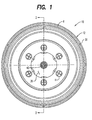
- the inner member 14 is generally hat-shaped having an enlarged flat or planar central portion 26 which is circular about a centerline D which is coaxial with the center line of the rim R of the wheel W .
- Rim mounting lugs (not shown) pass through holes H .
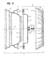
- the circular wheel cover 12 generally has an elongated for flattened U-shape cross sectional configuration, the circular, flat outside surface of which forms a cavity 22 for receiving the generally flat circular display or advertising disc 21 attached thereto by conventional means (not shown).
- the outer periphery 20 of the wheel cover 12 extends outwardly and inwardly from the generally flat central portion 18 so as to protectively surround the outer periphery of the inner member 14 and the rim engaging members 30 movably attached thereto as described herebelow.
- a counterweight 59 is provided for proper balancing about the centerline D .
- a plurality of evenly spaced wheel rim engaging members 30 are mounted in mating slots 33 formed into the planar annular shaped outer periphery 26 of the inner member 14 .
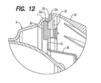
- Each of the rim engaging members 30 also includes a threaded aperture extending radially through one thinner section thereof as best seen in Figure 12 which is engaged by an elongated threaded fastener 32 which, in turn, is held within the outer flange 28 of the inner member 14 .
- each rim engaging member 30 By proper rotation of the threaded fastener 32 using a key fitted into the socket 32a , radial movement in the direction of arrow A of each rim engaging member 30 is independently accomplished so that the convex distal margin 30a matably engages into the concaved periphery F of rim R .
- the evenly-spaced rim engaging members 30 are lockably engageable into the concave portion F of the rim so as to properly secure and center the inner member 12 with respect to the rim R and its rotational axis D .
- the inner member 14 further includes a support bearing member 54 which is rigidly connected to the planar central portion 26 by its annular flange 54b and radial flange 54a .
- a support bearing member 54 which is rigidly connected to the planar central portion 26 by its annular flange 54b and radial flange 54a .
- the support bearing member 54 includes two spaced roller bearings 56 and 58 which supportively receive a support shaft 36 having an enlarged mounting flange 16 which is rigidly attached to the central inner surface of the wheel cover 12 within a mating cavity 24 by threaded evenly spaced threaded fasteners 59 .
- the outer cylindrical surface of the support shaft 36 is closely aligned for snug or close sliding fit within the inside diameter of the support bearings 56 and 58 .
- the support shaft with the display cover 12 rigidly connected thereto and outwardly positioned therefrom is slidably engageable into the bearings 56 and 58 of the support bearing member 54 .
- Clearance holes 64 provide access to wheel lug nuts which attach the wheel W to the axle (not shown)
- An elongated cylindrical locking member is there shown at numeral 38 including an elongated cylindrical shaft and an enlarged headed portion having a unique drive slot 55 formed therein.
- the locking member 38 snugly and slidably engages within an elongated aperture formed longitudinally through the support shaft 36 .
- the axis E of the elongated locking member 38 is offset from the longitudinal axis D which is concentric with the outer cylindrical surface of the support member 36 , the wheel W and the inner member 14 .
- a cam member 40 is mechanically attached by a set screw 50 to the distal end of the locking member 38 .
- a detent ball 42 and spring as seen in Figure 10 form a detent which snapably engage into a cavity 44 formed in the inner face of the cam 40 which mates against the distal end surface of the support shaft 36 .
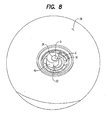
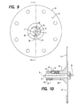
- a tab 52 which extends inwardly from the distal surface of the support shaft 36 , engages against a notched surface 46 or 48 of the cam member 40 to limit the rotation in the direction of the arrow about axis E as best seen in Figure 7.
- the cam member 40 may be moved into a rotational orientation as shown in Figure 10 so that it is in substantially cylindrical alignment within the cylindrical projected envelope defined by the support shaft 36 allowing insertion of the support shaft 36 into the support bearing member 54 as best shown in Figure 11. Thereafter, the locking member 38 may be rotated to another orientation of the cam member 40 by the insertion of a uniquely configured turning member or key (not shown) into cavity 55 wherein the cam member 40 rotating about offset axis E , causes an interference against the distal end of the support shaft 36 preventing removal of the wheel cover 12 as best seen in Figures 7, 8, 9 and 11.
- the locking member 38 may only be rotated into the unlocked position of cam member 40 shown in Figure 10 for removal of the wheel cover 12 by the holder of such a turning member or key
- an alternate embodiment of the inner member is there shown generally at numeral 60 .
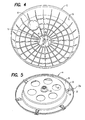
- an elongated flat offset bracket includes a central portion 62 which is outwardly offset along the rotational axis D of the rim R from flat outer mounting surfaces 64 and 66 .
- These outer mounting surfaces 64 and 66 include apertures which matably align with oppositely positioned studs which align the rim R onto the drive axle of the vehicle (not shown) and which thereafter are threadably engaged by lugs L .
- This embodiment 60 includes the same bearing support member 54 with its support flange 54a and support bearings 58 as previously described.
Landscapes
- Engineering & Computer Science (AREA)
- Mechanical Engineering (AREA)
- Vehicle Waterproofing, Decoration, And Sanitation Devices (AREA)
Applications Claiming Priority (4)
| Application Number | Priority Date | Filing Date | Title |
|---|---|---|---|
| US104653 | 2002-03-22 | ||
| US10/104,653 US6536848B1 (en) | 2002-03-22 | 2002-03-22 | Non-rotating display wheel cover |
| WOPCT/US02/33032 | 2002-10-15 | ||
| PCT/US2002/033032 WO2003082606A1 (en) | 2002-03-22 | 2002-10-15 | Non-rotating display wheel cover |
Publications (1)
| Publication Number | Publication Date |
|---|---|
| EP1346851A2 true EP1346851A2 (de) | 2003-09-24 |
Family
ID=22301633
Family Applications (1)
| Application Number | Title | Priority Date | Filing Date |
|---|---|---|---|
| EP03251652A Withdrawn EP1346851A2 (de) | 2002-03-22 | 2003-03-18 | Nichtrotierende Fahrzeugradkappe mit Anzeigevorrichtung |
Country Status (5)
| Country | Link |
|---|---|
| US (1) | US6536848B1 (de) |
| EP (1) | EP1346851A2 (de) |
| CN (1) | CN1476387A (de) |
| AU (1) | AU2002367834A1 (de) |
| WO (1) | WO2003082606A1 (de) |
Cited By (1)
| Publication number | Priority date | Publication date | Assignee | Title |
|---|---|---|---|---|
| US20230054086A1 (en) * | 2020-02-10 | 2023-02-23 | Ian Fletcher | Wheel Cover |
Families Citing this family (34)
| Publication number | Priority date | Publication date | Assignee | Title |
|---|---|---|---|---|
| JP3980445B2 (ja) * | 2002-08-13 | 2007-09-26 | 川崎重工業株式会社 | 小型走行船 |
| US20050035651A1 (en) * | 2003-08-15 | 2005-02-17 | Leslie Hsiao | Non-rotating display wheel cover |
| US6848751B1 (en) * | 2003-09-15 | 2005-02-01 | Wen Jen Yuan | Non-rotational emblem means as constantly upright-oriented on wheel disc |
| US20050062336A1 (en) * | 2003-09-18 | 2005-03-24 | Leslie Hsiao | Non-rotating display wheel cover |
| KR100546249B1 (ko) * | 2003-12-15 | 2006-01-26 | 김헌규 | 차량의 휠커버 |
| US6945609B2 (en) * | 2004-02-13 | 2005-09-20 | Advance Engineering Technology | Wheel cover apparatus and associated methods |
| US20060005440A1 (en) * | 2004-02-25 | 2006-01-12 | Young Scott J | Bicycle advertising and garphic display medium |
| US7347502B2 (en) * | 2004-03-04 | 2008-03-25 | Eric Scott Courtney | Wheel design |
| US7121631B2 (en) * | 2004-03-08 | 2006-10-17 | Strzelczyk Justin C | Spinner hub assembly |
| US7472966B2 (en) * | 2005-02-25 | 2009-01-06 | Static Media Group, Llc | Wheel cover assembly having stationary display and base member for mounting to a wheel |
| US20100037498A1 (en) * | 2005-02-25 | 2010-02-18 | Dovale Jr Anthony J | Vehicle wheel display assembly |
| US20070200421A1 (en) * | 2006-02-24 | 2007-08-30 | Dovale Anthony J Jr | Wheel cover |
| US20060255652A1 (en) * | 2005-02-25 | 2006-11-16 | Robert Kaufman | Vehicle wheel display assembly |
| US7472967B2 (en) * | 2005-09-21 | 2009-01-06 | Static Media Group, Llc | Vehicle wheel display assembly |
| US20060277806A1 (en) * | 2005-02-25 | 2006-12-14 | Dovale Anthony J Jr | Vehicle Wheel Display Assembly |
| US20060226697A1 (en) * | 2005-04-06 | 2006-10-12 | Samson Judith A | Apparatus and methods for covering a wheel |
| US20060238017A1 (en) * | 2005-04-25 | 2006-10-26 | Samson Judith A | Apparatus and methods for covering a wheel |
| US7524093B2 (en) * | 2005-12-16 | 2009-04-28 | Ronald Sinnette | Displaying image mechanism wheel assembly |
| US20070241607A1 (en) * | 2006-04-18 | 2007-10-18 | Phillip Hildebrand | Skateboard Wheel with Independently Rotating Disc Assemblies |
| JP4235234B2 (ja) * | 2007-07-09 | 2009-03-11 | 株式会社山水技研 | 静止ホイールカバー並びに静止ホイールカバーを使用した移動体 |
| US9266387B2 (en) * | 2009-01-05 | 2016-02-23 | Static Media, Llc | Vehicle wheel display assembly |
| DE102009049766A1 (de) * | 2009-10-17 | 2011-05-26 | Robert Reinert | Sonderradkappe, Zierscheibe für Quads |
| US9545817B2 (en) | 2013-02-27 | 2017-01-17 | Andres Velez | Non frictional wheel enhancing assembly |
| US9327340B1 (en) | 2013-09-16 | 2016-05-03 | Harry Bazerkanian | Method and apparatus for constructing a floating wheel cap |
| US10688554B2 (en) | 2013-09-16 | 2020-06-23 | Harry Bazerkanian | Non-rotating wheel cap |
| US9908364B2 (en) * | 2014-11-03 | 2018-03-06 | Joshua Haynes | Vehicle wheel center cap adapter |
| DE102015222174B4 (de) * | 2015-11-11 | 2024-11-28 | Bayerische Motoren Werke Aktiengesellschaft | Radhausabdeckung für eine Kraftfahrzeugkarosserie und hiermit ausgestattetes Kraftfahrzeug |
| CN106114051A (zh) * | 2016-08-17 | 2016-11-16 | 安徽江淮车轮有限公司 | 一种机动车用轮毂盘盖 |
| JP6477855B1 (ja) | 2017-12-26 | 2019-03-06 | トヨタ自動車株式会社 | 車両用のホイールカバーとそれを備える車両用駆動ユニット及び車両 |
| GB2577931B (en) * | 2018-10-11 | 2022-08-03 | Mclaren Automotive Ltd | Wheel cover |
| CN109203851B (zh) * | 2018-10-26 | 2020-05-12 | 徐州顺达钢轮制造有限公司 | 一种电动三轮车轮毂 |
| US11807041B2 (en) * | 2020-07-22 | 2023-11-07 | Paccar Inc | Floating wheel cover |
| US11338612B1 (en) | 2021-02-04 | 2022-05-24 | Jennifer Haynes | Wheel center cap assembly |
| US11155118B1 (en) | 2021-02-04 | 2021-10-26 | Jennifer Haynes | Wheel center cap assembly |
Citations (10)
| Publication number | Priority date | Publication date | Assignee | Title |
|---|---|---|---|---|
| US710195A (en) | 1901-12-19 | 1902-09-30 | Dora Jones | Advertising display device. |
| US2014058A (en) | 1934-05-01 | 1935-09-10 | Tonai Hideo | Hub cap |
| US2548070A (en) | 1948-11-22 | 1951-04-10 | Arthur M Ryan | Advertising display device |
| US2869262A (en) | 1957-06-03 | 1959-01-20 | Charles D Lucas | Wheel-supported advertizing signs |
| US4280293A (en) | 1979-12-26 | 1981-07-28 | Kovalenko Eugene N | Stationary display member for a rotating hub cap |
| US4678239A (en) | 1984-09-27 | 1987-07-07 | Yutaka Matsushita | Free wheel cap |
| US5588715A (en) | 1994-06-20 | 1996-12-31 | Harlen; Charles D. | Non-rotating wheel cover assembly |
| US5659989A (en) | 1994-07-13 | 1997-08-26 | Hsiao; Leslie | Wheel cover |
| US5957542A (en) | 1997-05-30 | 1999-09-28 | Boothe; Ralph T. | Theft-proof non-rotating wheel cover with replaceable ornament |
| US6120104A (en) | 1996-10-09 | 2000-09-19 | Okamoto; Yoshiaki | Wheel cover |
Family Cites Families (8)
| Publication number | Priority date | Publication date | Assignee | Title |
|---|---|---|---|---|
| US2169237A (en) | 1938-01-04 | 1939-08-15 | Gasco Pete | Stationary ornament for wheel hub caps |
| US2995402A (en) * | 1957-03-22 | 1961-08-08 | Lyon George Albert | Wheel cover |
| US4274679A (en) * | 1979-10-03 | 1981-06-23 | International Telephone And Telegraph Corporation | Wheel cover locking means |
| US4306751A (en) * | 1980-04-28 | 1981-12-22 | Rockwell International Corporation | Wheel cover mounting bracket |
| US4346940A (en) * | 1980-07-07 | 1982-08-31 | Del-Met Corporation | Wheel cover locking assemblies |
| US5190354A (en) | 1991-05-13 | 1993-03-02 | Serge Levy | Vehicle wheel cover |
| US5190345A (en) * | 1991-12-06 | 1993-03-02 | Topeak Inc. | Seat of a bicycle having a device for fastening a bag |
| US5490342A (en) | 1994-07-13 | 1996-02-13 | Rutterman; Michael J. | Non-rotating wheel cover |
-
2002
- 2002-03-22 US US10/104,653 patent/US6536848B1/en not_active Expired - Fee Related
- 2002-10-15 WO PCT/US2002/033032 patent/WO2003082606A1/en not_active Ceased
- 2002-10-15 AU AU2002367834A patent/AU2002367834A1/en not_active Abandoned
- 2002-10-15 CN CNA028030494A patent/CN1476387A/zh active Pending
-
2003
- 2003-03-18 EP EP03251652A patent/EP1346851A2/de not_active Withdrawn
Patent Citations (10)
| Publication number | Priority date | Publication date | Assignee | Title |
|---|---|---|---|---|
| US710195A (en) | 1901-12-19 | 1902-09-30 | Dora Jones | Advertising display device. |
| US2014058A (en) | 1934-05-01 | 1935-09-10 | Tonai Hideo | Hub cap |
| US2548070A (en) | 1948-11-22 | 1951-04-10 | Arthur M Ryan | Advertising display device |
| US2869262A (en) | 1957-06-03 | 1959-01-20 | Charles D Lucas | Wheel-supported advertizing signs |
| US4280293A (en) | 1979-12-26 | 1981-07-28 | Kovalenko Eugene N | Stationary display member for a rotating hub cap |
| US4678239A (en) | 1984-09-27 | 1987-07-07 | Yutaka Matsushita | Free wheel cap |
| US5588715A (en) | 1994-06-20 | 1996-12-31 | Harlen; Charles D. | Non-rotating wheel cover assembly |
| US5659989A (en) | 1994-07-13 | 1997-08-26 | Hsiao; Leslie | Wheel cover |
| US6120104A (en) | 1996-10-09 | 2000-09-19 | Okamoto; Yoshiaki | Wheel cover |
| US5957542A (en) | 1997-05-30 | 1999-09-28 | Boothe; Ralph T. | Theft-proof non-rotating wheel cover with replaceable ornament |
Cited By (1)
| Publication number | Priority date | Publication date | Assignee | Title |
|---|---|---|---|---|
| US20230054086A1 (en) * | 2020-02-10 | 2023-02-23 | Ian Fletcher | Wheel Cover |
Also Published As
| Publication number | Publication date |
|---|---|
| US6536848B1 (en) | 2003-03-25 |
| WO2003082606A1 (en) | 2003-10-09 |
| AU2002367834A1 (en) | 2003-10-13 |
| CN1476387A (zh) | 2004-02-18 |
Similar Documents
| Publication | Publication Date | Title |
|---|---|---|
| US6536848B1 (en) | Non-rotating display wheel cover | |
| US5957542A (en) | Theft-proof non-rotating wheel cover with replaceable ornament | |
| US4678239A (en) | Free wheel cap | |
| CN100506573C (zh) | 非旋转车轮盖 | |
| US2548070A (en) | Advertising display device | |
| US11607905B2 (en) | Wheel assemblies for model vehicles | |
| US6443529B1 (en) | Assembly with a non-rotatable wheel cover disc | |
| US6945609B2 (en) | Wheel cover apparatus and associated methods | |
| US5490342A (en) | Non-rotating wheel cover | |
| US20050062336A1 (en) | Non-rotating display wheel cover | |
| CA2702409A1 (en) | Removable wheel cover | |
| US20050035651A1 (en) | Non-rotating display wheel cover | |
| US10688554B2 (en) | Non-rotating wheel cap | |
| US20100037498A1 (en) | Vehicle wheel display assembly | |
| US20160052336A1 (en) | Method and Apparatus for Constructing a Floating Wheel Cap | |
| US20050062339A1 (en) | Non-rotating display wheel cover assembly | |
| US9327340B1 (en) | Method and apparatus for constructing a floating wheel cap | |
| US3918186A (en) | Wheel mounted display device | |
| US3847443A (en) | Spoked wheel and wheel ornament | |
| US20020079735A1 (en) | Rim extension device | |
| US3864860A (en) | Tire display apparatus | |
| US20070199220A1 (en) | Vehicle wheel display assembly | |
| US20060255652A1 (en) | Vehicle wheel display assembly | |
| US20230054086A1 (en) | Wheel Cover | |
| US12420584B2 (en) | Floating centercap for vehicle |
Legal Events
| Date | Code | Title | Description |
|---|---|---|---|
| PUAI | Public reference made under article 153(3) epc to a published international application that has entered the european phase |
Free format text: ORIGINAL CODE: 0009012 |
|
| 17P | Request for examination filed |
Effective date: 20030411 |
|
| AK | Designated contracting states |
Kind code of ref document: A2 Designated state(s): AT BE BG CH CY CZ DE DK EE ES FI FR GB GR HU IE IT LI LU MC NL PT RO SE SI SK TR |
|
| AX | Request for extension of the european patent |
Extension state: AL LT LV MK |
|
| STAA | Information on the status of an ep patent application or granted ep patent |
Free format text: STATUS: THE APPLICATION HAS BEEN WITHDRAWN |
|
| 18W | Application withdrawn |
Effective date: 20050426 |