EP1347140A2 - Cadre dormant pour portes et similaires - Google Patents
Cadre dormant pour portes et similaires Download PDFInfo
- Publication number
- EP1347140A2 EP1347140A2 EP03005908A EP03005908A EP1347140A2 EP 1347140 A2 EP1347140 A2 EP 1347140A2 EP 03005908 A EP03005908 A EP 03005908A EP 03005908 A EP03005908 A EP 03005908A EP 1347140 A2 EP1347140 A2 EP 1347140A2
- Authority
- EP
- European Patent Office
- Prior art keywords
- component element
- flat
- surface portion
- framework
- shaped
- Prior art date
- Legal status (The legal status is an assumption and is not a legal conclusion. Google has not performed a legal analysis and makes no representation as to the accuracy of the status listed.)
- Withdrawn
Links
Images





Classifications
-
- E—FIXED CONSTRUCTIONS
- E06—DOORS, WINDOWS, SHUTTERS, OR ROLLER BLINDS IN GENERAL; LADDERS
- E06B—FIXED OR MOVABLE CLOSURES FOR OPENINGS IN BUILDINGS, VEHICLES, FENCES OR LIKE ENCLOSURES IN GENERAL, e.g. DOORS, WINDOWS, BLINDS, GATES
- E06B1/00—Border constructions of openings in walls, floors, or ceilings; Frames to be rigidly mounted in such openings
- E06B1/04—Frames for doors, windows, or the like to be fixed in openings
- E06B1/06—Wooden frames
- E06B1/08—Wooden frames composed of several parts with respect to the cross-section of the frame itself
- E06B1/10—Wooden frames composed of several parts with respect to the cross-section of the frame itself adjustable with respect to the thickness of walls
Definitions
- the invention relates to a support framework for doors and similar elements, which is so shaped as to be fitted on the relative installation positions and to permit the doors and similar elements to be adapted thereon.
- Support frameworks for doors and similar elements are known, which are adapted to be fitted on to counter-frameworks applied along the peripheral edges of access openings for inhabited building walls, and each comprising a peripheral framework shaped with the shape and size and the relative access opening, so as to be secured for the entire thickness of the same opening, and constituted by an upper crosspiece and two vertical side stanchions, onto one of them there are fitted the pintles onto which the door and the like is supported and articulated.
- frameworls are prepared in advance and purposely for the different access openings, and need a set of working operations for being assembled on to each installation position, by employing hardware which can be found on the commerce, which is housed into grooved hollows obtained by milling the framework, and for assembling each door on to the framework, which often needs that some operations be performed for adapting the framework to imprecise masonries and for securing the door to the framework, which operations are required for adjusting correctly the door along the height and the vertical direction, in presence of measurement errors of the framework and/or the door and/or not perfectly executed housings.
- the present invention has the object to provide for a support framework for doors adapted to be Installed on access openings having different shape and size, in a simple and quick manner, without the need to prepare in advance from time to time particular frameworks for each needed installation, and with the possibility to adapt the framework to the masonry and to assemble correctly the door on to the same framework, without the need that additional workings on these component parts be performed, as in the case of the currently used frameworks.
- FIG. 1-5 schematically represent a peripheral framework 6 according to the invention, on a first embodiment thereof, which is adapted to support in an articulated manner some doors and similar elements which are installed on access openings for inhabited building walls, such framework being secured along the peripheral edges of each access opening, for the entire thickness thereof, and being constituted by an upper rectilinear crosspiece 7 with horizontal extent, and two rectilinear side stanchions 8 with vertical extent, joined to the horizontal crosspiece 7 by means of suitable joining means such as for example pins 9 (visible on Fig. 1), engaging corresponding cams (not shown) or fixing or coupling joints or similar means.
- suitable joining means such as for example pins 9 (visible on Fig. 1), engaging corresponding cams (not shown) or fixing or coupling joints or similar means.
- first side component element 10 and a second side component element 11 which are applied respectively on to a surface portion of the wall provided with the access opening and an opposite surface portion of that wall, or they are applied on to the counter-framework which already would have been secured to the peripheral edges of such access opening.
- this stanchion or crosspiece is constituted by a third and a fourth central component element 12 and 13, situated on a position interposed between said first and second component element and co-operating with each other as it will be described later on, as well as adapted to engage respectively the first and the second component element in the manner and for the function hereinafter described.
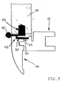
- first component element 10 and the second component element 11 are constituted by a respective convex curved surface portion 14 and 15 turned outwards and whose outer surface has the needed aesthetical and decorative appearance and performs the function of decorative frame, and are also constituted by a respective flat and indented surface portion 16 and 17, which are symmetrical with each other and turned toward each other, adapted to be laid on the corresponding building wall surfaces and secured to such walls by means of building binder material or fixing means commonly available on commerce, such flat surface portions being radiused with the relative convex surface portion with a reduced radius angle at one end portion thereof and with a respective further flat surface portion 18 and 19 at the other end portion thereof, which portion is turned toward the insertion zone of the door wing 20 (see Fig. 7).
- the flat and indented surfaces 16 and 17 of said first and second component element are formed by a respective slot 21 and 22, for joining the corresponding third and fourth central component element 12 and 13 as it will be described later on, and by a respective hollow 23 and 24 with a depth smaller than that of the slot, and whose function is to permit an effective adhesion of the component element to the walls or counter-frameworks having irregular surfaces, and to avoid possible dimensional and aesthetical changes of the convex surface portions of the same element, in presence of different thermal conditions, by compensating the material expansions or shrinkages as a consequence of such changed thermal conditions.
- At least one of the further flat surface portions in this case the portion 18, is shaped with a hollow 25 for adapting the corresponding door wing 20 which is assembled on the present framework as it will be hereinafter described.
- the third and fourth central component element 12 and 13 are so shaped as to be interposed between the first and the second component element 10 and 11, with the possibility to change the thickness of the present support framework within determinate extents, in the manner hereinafter described, to adapt such framework to walls and/or counter-frameworks with imprecise shape and/or not correct measures.
- the third component element 12 is shaped with a flat back surface 26 adapted to be adequately arranged on and secured to the wall or the counter-framework, and a front surface formed by a flat surface portion 27 and a hollowed surface portion 28, joined to the preceding one through a slot 29 assigned to house the door sealing gasket (not shown) and shaped with a hollow 30 aligned with the hollow 25 of the first component element 10, to house, together with such hollow 25, the hardware of the door 20.
- this third component element is shaped with a projection 31 joined with the hollowed surface portion 28 and adapted to be inserted in the corresponding slot 21 of the first component element when this latter is connected with a fixed or a coupling joint with the third component element.
- Such third component element 12 is further shaped with an enlarged cavity 32 at the side opposite to that where the projection 31 is provided, so as to permit the fourth component element 13 to be connected with a fixed or a coupling joint thereto, as it will be hereinafter described.
- the fourth component element 13 is shaped with a flat back surface 33 adapted to be suitably arranged on and secured to the wall or the counter-framework, and with a flat front surface 34 which are spaced away of an extent identical to the thickness of the same component element, and joined to each other respectively with a flat terminal surface 35 where a narrow slot 36 is provided at the end portion turned toward the enlarged cavity 32, and a projection 37 and a hollow 38 at the end portion turned toward the second component element 11.
- this fourth component element is realized with such a thickness as to allow its projection 37 to be inserted or coupled on the corresponding slot 22 of the second component element, when this latter is coupled with said fourth component element, and its flat terminal surface 35 to be inserted or coupled on the corresponding enlarged cavity 32 of the third component element 12, when this latter is coupled with said fourth component element.
- the Fig. 3 makes it evident the framework on the condition of reciprocal coupling of its four component elements, in which the terminal surface 35 of the fourth component element 13 is coupled with the enlarged cavity 32 of the third component element 12, in a way to space away from each other the various component elements of the extent needed to adapt them to the inhabited building wall or counter-framework. Besides, the Fig.
- the coupling of the third component element with the fourth component element is made possible by adding at least a spacer (not shown), shaped for being coupled at one end portion thereof with the enlarged cavity 32 of the third component element 12 and at the other end portion thereof with the slot 36 of the fourth component element 13, and dimensioned in such a manner that to permit with its use to increase the distance between the first component element 10 and the second component element 12, thereby adapting the present framework to walls or counter-frameworks with larger thicknesses.
- a spacer (not shown), shaped for being coupled at one end portion thereof with the enlarged cavity 32 of the third component element 12 and at the other end portion thereof with the slot 36 of the fourth component element 13, and dimensioned in such a manner that to permit with its use to increase the distance between the first component element 10 and the second component element 12, thereby adapting the present framework to walls or counter-frameworks with larger thicknesses.
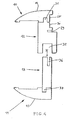
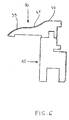
- Figs. 5 and 6 show now the first component element 10 made on different versions thereof, whose convex curved surface portion 14 has, with respect to the curved surface portion of the previous element 10, a bending with different bending radius (Fig.
- a special hardware 42 is employed, which is formed by a first and a second bent shank 43 and 44 joined together and with a head 45, of which the first shank 43 is bent for being housed on and fixed to the pre-formed cavity of the first and third component element 10, 12 and defined by the respective hollows 25 and 30 of said component elements, and the second shank 44 is bent orthogonally thereto, for being inserted on and fixed to the door wing or panel 20, while the head 45 is slightly projected laterally with respect to the outer profile of both said first component element and said wing.
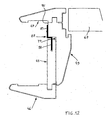
- FIGS. 8-12 schematically represent a peripheral framework 1 according to the invention, on a second embodiment thereof, which is made for the same purposes of the previously described framework.
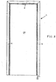
- Fig. 9 in which the side view of a door or similar elements is shown, and to Fig. 10 in which the side cross-section of one of the stanchions or the crosspiece of the framework 1, on a plan view and for the entire thickness thereof is shown, it is noted that it is substantially constituted by a first side component element 46, a second side component element 47 and a third and a fourth central component element 48 and 49, co-operating with each other and performing the same function of the above described components.
- first component element 46 and the second component element 47 are constituted by a respective pair of surface portions 50, 51 and 52, 53 turned outwards, and whose outer surface portions have the required aesthetical and decorative appearance and perform the function of a decorative frame, and are also constituted by a respective flat and indented surface portion 54 and 55, symmetrical and turned toward each other, adapted to be laid on to the corresponding building wall surfaces and secured to such walls by means of building binder or fixing means commonly available on commerce, such flat surface portions being radiused with the relative surfaces 50 and 52 with a corresponding curved surface 56 and 57 with reduced radius angle and a flat surface 58 and 59 at one end portion thereof, and with a respective further flat surface portion 60 and 61 at the other end portion thereof, which portion is turned toward the door wing insertion zone (see Figs.
- the flat and indented surfaces 54 and 55 of said first and second component element are formed by a respective slot 62 and 63, for joining the corresponding third and fourth central component element 48 and 49 as it will be described, and by a respective hollow 64 and 65 with depth smaller than that of the slot, and whose function is that to permit an effective adhesion of the component element to the walls or counter-frameworks with irregular surfaces and to avoid possible dimensional and aesthetical changes of the convex surface portions of the same element, in presence of different thermal conditions, by compensating the material expansions and shrinkages as a consequence of such changed thermal conditions.
- At least one of the further flat surface portions in this case the portion 54, is shaped with a slot 66 for housing the corresponding wing 67 of the door 68, which is assembled on the present framework as it will be described.
- the third and fourth central component element 48 and 49 are shaped for being interposed between the first and second component element 46 and 47, with the possibility to change within determinate extents the thickness of the present support framework, in the manner which will be described, for adapting such framework to walls and/or counter-frameworks with inaccurate shape and/or not correct measures.
- the third component element 48 is shaped with a flat back surface 69 adapted to be arranged on and adequately secured to the wall and/or the counter-framework, and a front flat surface 70, which are spaced away of an extent identical to the thickness of the same component element, and radiused to each other respectively with a flat terminal surface 71, in which a narrow slot 72 is provided at the end portion thereof turned toward the fourth component element 49, and a projection 73 and a hollow 74 at the end portion thereof turned toward the first component element 46.
- this third component element 48 is made with such a thickness that to permit its projection 73 to be inserted and coupled on the corresponding slot 62 of the first component element 46, when this latter is coupled with said third component element 48, and the removable coupling of its flat terminal surface 71 with the fourth component element 49, in the manner which will be described.
- the fourth component element 49 is shaped with a back surface formed by a flat surface portion 75 adapted to be arranged on and secured properly to the wall or the counter-framework, and by a hollowed surface portion 76 shaped with a hollow 77 adapted to house a part of or the whole third component element 48, by arranging the front flat surface 70 of this latter on to such hollowed surface portion 76 of the hollow 77, on the coupled condition of the component elements 48 and 49, and by letting such front flat portion 70 to slide along the hollow 77 up to the desired adjustment position thereof.
- the back surface of the component element 49 is also radiused with a front surface, formed by a skew surface portion 78, a flat surface portion 79 and a hollowed surface portion 80, radiused with the previous one with a slot 81 assigned to house the door sealing gasket (not shown) and shaped with a slot 82 aligned with the slot 66 of the second component element 47 for housing, together with such slot 66, the hardware of the wing 67.
- this fourth component element 49 is shaped with a projection 83 radiused with the back surface and adapted to be inserted in the corresponding slot 63 of the second component element 47, when this latter is joined by a fixed or a coupling joint with the fourth component element 49, such hollowed surface portion 76 and skew surface 78 being radiused to each other by means of a curved surface 84 with reduced radius angle and a skew surface 85.
- FIG. 11 also shows the mode of applying the wing or panel 67 of the door 68 on the present support framework, wherein it is noted that also in this case a special hardware 42 is employed, which is formed in the same manner than that described, and that this applying mode of this wing or panel is also performed as previously described, for the same purposes and the same previously described advantages.
- a special hardware 42 is employed, which is formed in the same manner than that described, and that this applying mode of this wing or panel is also performed as previously described, for the same purposes and the same previously described advantages.
- Fig. 11 also shows the mode of applying the wing or panel 67 of the door 68 on the present support framework, wherein it is noted that also in this case a special hardware 42 is employed, which is formed in the same manner than that described, and that this applying mode of this wing or panel is also performed as previously described, for the same purposes and the same previously described advantages.
- Fig. 11 also shows the mode of applying the wing or panel 67 of the door 68 on the present support framework, where
- the present framework to be put on place in a way that the first and the third component elements 46 and 48 as well as the second and the fourth component elements 47 and 49 are coupled in advance to each other, and thereafter to join these component units with the profiled square 87, in order to simplify the operations and working times required for putting them on place, like cutting the finishing frames and putting them on place, with consequent quick and extremely accurate assembling of the present peripheral framework, since all operations and cuttings performed on the various component elements are effected on the factory with high technology operating automatic machines.
- the visible surfaces of all component elements may be shaped also with forms and aesthetical and decorative appearances different than those indicated solely by way of example, thus without departing from the protection sphere of the present invention.
Landscapes
- Engineering & Computer Science (AREA)
- Life Sciences & Earth Sciences (AREA)
- Wood Science & Technology (AREA)
- Civil Engineering (AREA)
- Structural Engineering (AREA)
- Securing Of Glass Panes Or The Like (AREA)
- Building Environments (AREA)
Applications Claiming Priority (2)
| Application Number | Priority Date | Filing Date | Title |
|---|---|---|---|
| ITPN20020018 ITPN20020018A1 (it) | 2002-03-20 | 2002-03-20 | Telaio di sostegno per porte ed elementi simili. |
| ITPN20020018 | 2002-03-20 |
Publications (2)
| Publication Number | Publication Date |
|---|---|
| EP1347140A2 true EP1347140A2 (fr) | 2003-09-24 |
| EP1347140A3 EP1347140A3 (fr) | 2004-09-08 |
Family
ID=27773201
Family Applications (1)
| Application Number | Title | Priority Date | Filing Date |
|---|---|---|---|
| EP03005908A Withdrawn EP1347140A3 (fr) | 2002-03-20 | 2003-03-17 | Cadre dormant pour portes et similaires |
Country Status (2)
| Country | Link |
|---|---|
| EP (1) | EP1347140A3 (fr) |
| IT (1) | ITPN20020018A1 (fr) |
Cited By (5)
| Publication number | Priority date | Publication date | Assignee | Title |
|---|---|---|---|---|
| ITVI20090285A1 (it) * | 2009-11-27 | 2011-05-28 | Barausse S P A | Telaio per porte perfezionato |
| EP2383414A3 (fr) * | 2010-04-28 | 2014-09-10 | Door 2000 Srl | Menuiserie pour portes dans des immeubles d'habitation |
| ES2727611A1 (es) * | 2018-04-16 | 2019-10-17 | Cambil Miguel Morales | Marco todo en uno de montaje rápido para puertas |
| WO2020148469A1 (fr) * | 2019-01-16 | 2020-07-23 | Miguel Morales Cambil | Profilé en bois pour châssis fixe de portes et fenêtres |
| BE1029731B1 (nl) * | 2021-09-06 | 2023-04-03 | MI CASA nv | Werkwijze voor het vormen van een wand van een gebouw en een gebouw met een volgens deze werkwijze gevormde wand |
Family Cites Families (5)
| Publication number | Priority date | Publication date | Assignee | Title |
|---|---|---|---|---|
| US3599373A (en) * | 1969-09-22 | 1971-08-17 | Wayne C Coykendall | Prefabricated door assembly |
| FR2153810A5 (fr) * | 1971-09-24 | 1973-05-04 | Almelet Robert | |
| FR2257764A1 (en) * | 1974-01-10 | 1975-08-08 | Monneron Maurice | Extruded plastic or metal section door frame - has central channel and opposite hollow edge projections |
| AU4266078A (en) * | 1978-01-06 | 1979-07-12 | Reuter P A | Door fram assembly |
| DE4021877A1 (de) * | 1989-08-30 | 1991-04-18 | Franz Karl Rudolf | Tuerfutter-tuerzarge |
-
2002
- 2002-03-20 IT ITPN20020018 patent/ITPN20020018A1/it unknown
-
2003
- 2003-03-17 EP EP03005908A patent/EP1347140A3/fr not_active Withdrawn
Cited By (5)
| Publication number | Priority date | Publication date | Assignee | Title |
|---|---|---|---|---|
| ITVI20090285A1 (it) * | 2009-11-27 | 2011-05-28 | Barausse S P A | Telaio per porte perfezionato |
| EP2383414A3 (fr) * | 2010-04-28 | 2014-09-10 | Door 2000 Srl | Menuiserie pour portes dans des immeubles d'habitation |
| ES2727611A1 (es) * | 2018-04-16 | 2019-10-17 | Cambil Miguel Morales | Marco todo en uno de montaje rápido para puertas |
| WO2020148469A1 (fr) * | 2019-01-16 | 2020-07-23 | Miguel Morales Cambil | Profilé en bois pour châssis fixe de portes et fenêtres |
| BE1029731B1 (nl) * | 2021-09-06 | 2023-04-03 | MI CASA nv | Werkwijze voor het vormen van een wand van een gebouw en een gebouw met een volgens deze werkwijze gevormde wand |
Also Published As
| Publication number | Publication date |
|---|---|
| ITPN20020018A1 (it) | 2003-09-22 |
| EP1347140A3 (fr) | 2004-09-08 |
Similar Documents
| Publication | Publication Date | Title |
|---|---|---|
| US8316606B2 (en) | Fastening system for panels and trim | |
| US9540801B2 (en) | Multi-piece truss plate for use in joining two structural members | |
| EP2578763B1 (fr) | Fenêtre pour installation dans une structure de toit comprenant un certain nombre de supports de montage | |
| EP0641902A1 (fr) | Système d'assemblage de profilés pour réaliser des façades continus pour bâtiments civils ou similaires | |
| KR20150003622A (ko) | 석재 오픈 조인트용 연결철물 및 이를 이용한 석재의 고정구조 | |
| JP2016191249A (ja) | 外壁部材の留付補助具およびその施工方法 | |
| US7174691B2 (en) | Aluminum profile system for placing doors, windows and partition walls | |
| JPS6013981Y2 (ja) | 既設の旧窓枠に新窓枠を取付ける装置 | |
| CN211500289U (zh) | 一种快速安装窗框 | |
| JPS6319672B2 (fr) | ||
| KR101735631B1 (ko) | H형 클립을 이용한 베이스 패널 부착 시공방법 | |
| JPH0813921A (ja) | 戸枠用補正金具、および補正金具を備えた戸枠 | |
| CN109914604B (zh) | 弧形屋脊及其加工方法 | |
| JP7199297B2 (ja) | 分割枠材及び建具 | |
| CN210288700U (zh) | 弧形屋脊 | |
| JPS6222577Y2 (fr) | ||
| JP4375034B2 (ja) | 壁パネルの目地部連結構造、並びに壁パネルの目地施工方法 | |
| CN111058725B (zh) | 一种高精度快速安装窗框 | |
| JP4056950B2 (ja) | サッシ窓枠の固定金具及び固定方法 | |
| JP2001271476A (ja) | 建築板用留め付け部材、該留め付け部材を固定した建築板、及びその留め付け構造 | |
| JP2000129801A (ja) | 壁パネルの連結構造 | |
| JPS6035749Y2 (ja) | 建具 | |
| JP2509148Y2 (ja) | 連装シヤツタ―における内マグサの連結構造 | |
| JP3001370B2 (ja) | 分割方立の連結装置 | |
| KR200360380Y1 (ko) | 창틀 |
Legal Events
| Date | Code | Title | Description |
|---|---|---|---|
| PUAI | Public reference made under article 153(3) epc to a published international application that has entered the european phase |
Free format text: ORIGINAL CODE: 0009012 |
|
| AK | Designated contracting states |
Kind code of ref document: A2 Designated state(s): AT BE BG CH CY CZ DE DK EE ES FI FR GB GR HU IE IT LI LU MC NL PT RO SE SI SK TR |
|
| AX | Request for extension of the european patent |
Extension state: AL LT LV MK |
|
| PUAL | Search report despatched |
Free format text: ORIGINAL CODE: 0009013 |
|
| AK | Designated contracting states |
Kind code of ref document: A3 Designated state(s): AT BE BG CH CY CZ DE DK EE ES FI FR GB GR HU IE IT LI LU MC NL PT RO SE SI SK TR |
|
| AX | Request for extension of the european patent |
Extension state: AL LT LV MK |
|
| AKX | Designation fees paid |
Designated state(s): AT BE BG CH CY CZ DE DK EE ES FI FR GB GR HU IE IT LI LU MC NL PT RO SE SI SK TR |
|
| STAA | Information on the status of an ep patent application or granted ep patent |
Free format text: STATUS: THE APPLICATION IS DEEMED TO BE WITHDRAWN |
|
| 18D | Application deemed to be withdrawn |
Effective date: 20050309 |