EP1347209B1 - Boîtes de vitesses - Google Patents
Boîtes de vitesses Download PDFInfo
- Publication number
- EP1347209B1 EP1347209B1 EP20030001076 EP03001076A EP1347209B1 EP 1347209 B1 EP1347209 B1 EP 1347209B1 EP 20030001076 EP20030001076 EP 20030001076 EP 03001076 A EP03001076 A EP 03001076A EP 1347209 B1 EP1347209 B1 EP 1347209B1
- Authority
- EP
- European Patent Office
- Prior art keywords
- drive
- variator
- clutch
- transmission
- gear
- Prior art date
- Legal status (The legal status is an assumption and is not a legal conclusion. Google has not performed a legal analysis and makes no representation as to the accuracy of the status listed.)
- Expired - Lifetime
Links
Images
Classifications
-
- F—MECHANICAL ENGINEERING; LIGHTING; HEATING; WEAPONS; BLASTING
- F16—ENGINEERING ELEMENTS AND UNITS; GENERAL MEASURES FOR PRODUCING AND MAINTAINING EFFECTIVE FUNCTIONING OF MACHINES OR INSTALLATIONS; THERMAL INSULATION IN GENERAL
- F16H—GEARING
- F16H37/00—Combinations of mechanical gearings, not provided for in groups F16H1/00 - F16H35/00
- F16H37/02—Combinations of mechanical gearings, not provided for in groups F16H1/00 - F16H35/00 comprising essentially only toothed or friction gearings
- F16H37/021—Combinations of mechanical gearings, not provided for in groups F16H1/00 - F16H35/00 comprising essentially only toothed or friction gearings toothed gearing combined with continuously variable friction gearing
-
- B—PERFORMING OPERATIONS; TRANSPORTING
- B60—VEHICLES IN GENERAL
- B60K—ARRANGEMENT OR MOUNTING OF PROPULSION UNITS OR OF TRANSMISSIONS IN VEHICLES; ARRANGEMENT OR MOUNTING OF PLURAL DIVERSE PRIME-MOVERS IN VEHICLES; AUXILIARY DRIVES FOR VEHICLES; INSTRUMENTATION OR DASHBOARDS FOR VEHICLES; ARRANGEMENTS IN CONNECTION WITH COOLING, AIR INTAKE, GAS EXHAUST OR FUEL SUPPLY OF PROPULSION UNITS IN VEHICLES
- B60K17/00—Arrangement or mounting of transmissions in vehicles
- B60K17/34—Arrangement or mounting of transmissions in vehicles for driving both front and rear wheels, e.g. four wheel drive vehicles
- B60K17/348—Arrangement or mounting of transmissions in vehicles for driving both front and rear wheels, e.g. four wheel drive vehicles having differential means for driving one set of wheels, e.g. the front, at one speed and the other set, e.g. the rear, at a different speed
- B60K17/35—Arrangement or mounting of transmissions in vehicles for driving both front and rear wheels, e.g. four wheel drive vehicles having differential means for driving one set of wheels, e.g. the front, at one speed and the other set, e.g. the rear, at a different speed including arrangements for suppressing or influencing the power transfer, e.g. viscous clutches
-
- F—MECHANICAL ENGINEERING; LIGHTING; HEATING; WEAPONS; BLASTING
- F16—ENGINEERING ELEMENTS AND UNITS; GENERAL MEASURES FOR PRODUCING AND MAINTAINING EFFECTIVE FUNCTIONING OF MACHINES OR INSTALLATIONS; THERMAL INSULATION IN GENERAL
- F16H—GEARING
- F16H37/00—Combinations of mechanical gearings, not provided for in groups F16H1/00 - F16H35/00
- F16H37/02—Combinations of mechanical gearings, not provided for in groups F16H1/00 - F16H35/00 comprising essentially only toothed or friction gearings
- F16H37/021—Combinations of mechanical gearings, not provided for in groups F16H1/00 - F16H35/00 comprising essentially only toothed or friction gearings toothed gearing combined with continuously variable friction gearing
- F16H2037/025—Combinations of mechanical gearings, not provided for in groups F16H1/00 - F16H35/00 comprising essentially only toothed or friction gearings toothed gearing combined with continuously variable friction gearing having continuously variable friction gearing, i.e. CVT, in which the ratio coverage is used more than once to produce the overall transmission ratio coverage, e.g. by shift to end of range, then change ratio in sub-transmission and shift CVT through range once again
-
- F—MECHANICAL ENGINEERING; LIGHTING; HEATING; WEAPONS; BLASTING
- F16—ENGINEERING ELEMENTS AND UNITS; GENERAL MEASURES FOR PRODUCING AND MAINTAINING EFFECTIVE FUNCTIONING OF MACHINES OR INSTALLATIONS; THERMAL INSULATION IN GENERAL
- F16H—GEARING
- F16H3/00—Toothed gearings for conveying rotary motion with variable gear ratio or for reversing rotary motion
- F16H3/006—Toothed gearings for conveying rotary motion with variable gear ratio or for reversing rotary motion power being selectively transmitted by parallel flow paths, e.g. dual clutch transmissions
-
- F—MECHANICAL ENGINEERING; LIGHTING; HEATING; WEAPONS; BLASTING
- F16—ENGINEERING ELEMENTS AND UNITS; GENERAL MEASURES FOR PRODUCING AND MAINTAINING EFFECTIVE FUNCTIONING OF MACHINES OR INSTALLATIONS; THERMAL INSULATION IN GENERAL
- F16H—GEARING
- F16H61/00—Control functions within control units of change-speed- or reversing-gearings for conveying rotary motion ; Control of exclusively fluid gearing, friction gearing, gearings with endless flexible members or other particular types of gearing
- F16H61/66—Control functions within control units of change-speed- or reversing-gearings for conveying rotary motion ; Control of exclusively fluid gearing, friction gearing, gearings with endless flexible members or other particular types of gearing specially adapted for continuously variable gearings
- F16H61/662—Control functions within control units of change-speed- or reversing-gearings for conveying rotary motion ; Control of exclusively fluid gearing, friction gearing, gearings with endless flexible members or other particular types of gearing specially adapted for continuously variable gearings with endless flexible members
Definitions
- the invention relates to a speed change gear, in particular for motor vehicles, according to the preamble of claim 1.
- Speed change gears in motor vehicles with a variator such as a belt drive or a toroidal provide high ride comfort and excellent adaptability to the efficiency favorable operation of the drive motor in dynamic driving due to the stepless speed changes, however, the interpretation of the transmission to high engine performance, especially in defined transmission ranges be critical.
- the JP 59 205058 A which is considered to represent the closest prior art, shows a speed change gearbox having a first driveline having a first clutch for activating the variator and a second driveline having a second clutch for activating a constant speed ratio.
- the clutch for activating the variator is disposed downstream of the first driveline between the variator and the constant ratio.
- the clutch for activating the constant ratio is arranged at the input of the constant ratio.
- the object of the invention is to propose a speed change gear, which is compact, simple and robust and which is suitable for the transmission of high engine power with favorable transmission efficiency in all speeds.
- the transmission has a first drive train with a clutch for activating the variator and a second drive train with a second clutch for activating the at least one constant gear ratio, whereby it can be switched over the said friction clutches via the one and / or the second Powertrain is operable.
- the second drive train has two constant gear transmission stages, which are designed as a starting and an economy gear ratio and which are switchable in the second drive train via clutches.
- the proposed Constantüber sheen thus cover exactly the areas that are systematically the critical areas in variators such as a belt transmission (beginning and Endüber GmbHs Kunststoffe) and / or can also contribute to increase the transmission total spread advantageous.
- the motor vehicle can be approached via the one drive train and the approach stage with a simple gear drive, with increasing speed is sliding over the other drive train and the variator in the continuously variable operation passed.
- the first drive train is again slidably activated, with a shift clutch in terms of translation "long" economy gear ratio is connected by means of a simple constant gear stage.
- both drive trains can be activated by closing both friction clutches at short-term and / or speed-dependent, where logically the variator must be set exactly to the switched constant gear ratio of the one drive train or a compensation element (eg power split, clutch with controlled slip) between the two drive trains is to be provided.
- a compensation element eg power split, clutch with controlled slip
- the first drive train has a drive shaft acting on the variator and the second drive train has a hollow shaft arranged coaxially therewith, the hollow shaft carrying the drive gears of the constant-starting step and economy gear step designed as simple spur gear drives.
- the variator in turn acts on a common output shaft, which also receives the corresponding gears of the constant gear ratios. This results in a robust and low-cost manufacturing engineering and less expensive gear design.
- the variator can also be a belt drive with hydraulically adjustable drive and driven pulley pairs and a chain or a belt as a belt, wherein the driven pulley pair is arranged directly on said output shaft, while the pair of drive pulleys is positioned via a spur gear on another countershaft.
- the two drive trains are activated due to the proposed coaxial design with a hollow shaft by a compact frictional double clutch, which advantageously allows a reduction of the structural and control technical effort. It may also be advantageous if a third clutch in the variator activating drive train is arranged on the output side, because thereby the variator, for example, in economy mode on the other drive train efficiency and low wear conditions can be stopped.
- the variator can be designed as an i 2 transmission in which the variator can be driven through the drive flux twice by corresponding parallel connection of a further spur gear drive and corresponding clutches, as a result of which its spread is squared or its required installation space is reduced.
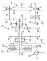
- the schematic drawing shows a speed change transmission for motor vehicles with a double friction clutch, a first drive train with a belt drive as a variator, a second drive train with two constant ratios and an integrated differential.
- the speed change gearbox 10 for motor vehicles which is shown only schematically as a block diagram, is arranged in a gear housing, not shown, and has a first input shaft 12, a designed as a hollow shaft 14 second input shaft space and variator achsabstands Struktur, a countershaft 16 and a common output shaft 18 on.
- the said waves are rotatably mounted in the not shown gear housing.
- the countershaft 16 may optionally be omitted.
- the hollow shaft 14 carries two switchable Los gears 20,22, which form fixed gearwheels 24, 26 on the output shaft 18 two constant gear ratios, namely the gears 20, 24, a starting gear ratio and the two gears 22, 26 a " long "economy translation, which reduces noise, fuel-saving and wear-reducing, especially in constant highway driving.
- the loose gears 20, 22 are coupled by means of a conventional synchronizer clutch S1 with a corresponding sliding sleeve with the hollow shaft 14 or decoupled from this.
- two loose gears 28, 30 are then mounted on the input shaft 12 axially to the hollow shaft 14, of which the gear 28 in conjunction with a reverse gear 32 and a fixed gear 34 on the output shaft 18 forms a reverse gear.
- the reversing gear 32 is mounted rotatably on a stub shaft 36 in the gear housing, not shown.
- the second idler gear 30 forms with a fixed gear 38 on the countershaft 16 a spur gear for the downstream variator or Umschlingungswandler 40, which consists of a pair of drive pulleys 42 on the countershaft 16, a seated on the output shaft 18 driven pulley pair 44 and a belt or a link chain 46 composed.
- the loose gears 28, 30 are in turn coupled via a synchronizer clutch S2 (or a dog clutch) with a corresponding sliding sleeve with the input shaft 12 or decoupled from this.
- a synchronizer clutch S2 or a dog clutch
- the input shaft 12 and the hollow shaft 14 are connected to a friction clutch double clutch K1, K2, on the other hand, for example, driven by the power output shaft 48 of an internal combustion engine of the motor vehicle.
- the dual clutch may be hydraulically controlled in a known manner and selectively couple the hollow shaft 14 or the input shaft 12 or both together with the power output shaft 48.
- clutches or synchronous clutches S1 and S2 are actuated in a manner not shown automatically via a corresponding control device or manually by means of a conventional selector lever.
- the output shaft 18 carries at its end opposite the variator 40, a drive pinion 50 for driving a differential 52, not shown, for example, a bevel gear differential for driving the front wheels of the motor vehicle.
- the synchronizer clutch S1 is switched so that the gear 20 is coupled to the hollow shaft 14 with open dual clutch K1, K2. Then, the friction clutch K2 is closed, and thus the starting process is initiated, wherein the power flow through the one drive train of the transmission 10, namely from the clutch K2 via the hollow shaft 14, the gears 20, 24 and the output shaft 18.
- the variator 40 is disconnected from the input shaft 12 due to the open synchronous clutch S2 and clutch K1 and transmits no drive power.
- the synchronizer clutch S2 is switched so that the gear 30 is coupled to the input shaft 12. Then, the clutch K2 is opened and at the same time the clutch K1 closed, which can be controlled by appropriate slip control of the clutches K1, K2 a jerk-free, comfortable change of power flow.
- the gearwheel 22 is coupled to the hollow shaft 14 by means of the synchronizer clutch S1, then the clutch K1 is opened and the clutch K2 is closed at the same time.
- the power flow is again via the above-described drive train with the hollow shaft 14, wherein the set constant gear can correspond to a so-called overdrive (or e-gear).
- the clutch K3 may be a hydraulically actuated multi-plate clutch. By opening the clutch K3 in economy mode, the variator 40 is stopped, reducing the wear and the efficiency of the transmission 10 is increased in economy mode.
- the reverse gear of the transmission 10 is switchable by the synchronizer clutch S2, the gear 28 with the input shaft 12 couples and the frictionally engaged clutch K1 is closed.
- the overall spread of the transmission 10 can be increased;
- the constant translations mentioned can also serve to cover the critical variator areas in the smallest and largest gear ratios in order to exclude impermissible wear and / or overloads.
- the variator could be designed as i 2 transmission, in which after passing through the Conversion region of the power flow reversed and quasi in the return using a spur gear with a defined ratio and corresponding switching of clutches of the conversion range can be quadrized or the variator 40 is correspondingly compact executable (eg reduction in the chain length).
- the portion 18b of the output shaft 18 could form another, connectable to a propeller shaft output (by appropriate implementation by the gear housing and arrangement of Abretesflansches), by means of which the rear wheels of the motor vehicle could be driven.
- a clutch K3 a slip-controlled clutch could be used to compensate for the speed differences resulting at the portions 18a and 18b of the output shaft 18.
Landscapes
- Engineering & Computer Science (AREA)
- General Engineering & Computer Science (AREA)
- Mechanical Engineering (AREA)
- Transmission Devices (AREA)
- Hybrid Electric Vehicles (AREA)
Claims (7)
- Boîte de vitesses, en particulier pour véhicules automobiles, avec un variateur à réglage continu et au moins un rapport de transmission constant ainsi qu'avec- une première chaîne cinématique avec un premier embrayage (K1) servant à activer le variateur (40), et- une deuxième chaîne cinématique avec un deuxième embrayage (K2) servant à activer l'au moins un rapport de transmission constant (20, 24 et 22, 26),caractérisée en ce que
la deuxième chaîne cinématique présente deux rapports de transmission constants (20, 24 et 22, 26), qui sont conçus comme un rapport de transmission de démarrage (20, 24) et un rapport de transmission pour des vitesses élevées du véhicule (22, 26) et qui sont embrayables dans la deuxième chaîne cinématique par le biais d'un troisième embrayage (S1),
la première chaîne cinématique présente un arbre d'entrée (12) agissant sur le variateur (40) et la deuxième chaîne cinématique, un arbre creux (14) agencé de manière coaxiale par rapport à la première, l'arbre creux (14) portant les roues dentées motrices (20, 22) des rapports de transmission constants, dont les roues dentées correspondantes (24, 26) sont fixées sur un arbre de sortie (18) commun aux deux chaînes cinématiques (12, 14) et
le premier et deuxième embrayages (K1, K2), qui activent les chaînes cinématiques, forment un double embrayage par friction disposé au niveau de l'arbre d'entrée (12) et au niveau de l'arbre creux (14). - Boîte de vitesses selon la revendication 1, caractérisée en ce qu'une chaîne cinématique présente un embrayage (S2) au moyen duquel le variateur (40) ou un rapport de marche arrière constant peut être connecté.
- Boîte de vitesses selon la revendication 1 ou 2, caractérisée en ce que le variateur est un convertisseur d'enroulement (40), dont la paire de disques d'entraînement (42) est reliée par entraînement à l'arbre d'entrée (12) par le biais d'un rapport intermédiaire (30, 38) et d'un arbre intermédiaire (16) et dont la paire de disques d'entraînement (44) est agencée directement sur l'arbre de sortie (18).
- Boîte de vitesses selon une ou plusieurs des revendications 1 à 3, caractérisée en ce que le variateur (40) est positionné axialement derrière l'arbre creux (14) de la deuxième chaîne cinématique.
- Boîte de vitesses selon une ou plusieurs des revendications 1 à 4, caractérisée en ce qu'un autre embrayage (K3) est prévu, côté sortie du variateur (40), dans l'arbre de sortie (18a, 18b), au moyen duquel le variateur (40) peut être désaccouplé lorsque la deuxième chaîne cinématique (14) est activée.
- Boîte de vitesses selon une ou plusieurs des revendications 1 à 5, caractérisée en ce que le variateur est réalisé sous forme de boîte de vitesses i2 pour passer deux fois la transmission continue.
- Boîte de vitesse selon une ou plusieurs des revendications 1 à 6, caractérisée en ce que dans une boîte de vitesses (10) avec une deuxième sortie, par exemple pour quatre roues motrices ou un entraînement à roues indépendantes d'un essieu d'entraînement, une des chaînes cinématiques (14) agit sur une des sorties (50) et l'autre chaîne cinématique (12) sur l'autre sortie, par exemple pour l'essieu arrière.
Applications Claiming Priority (2)
| Application Number | Priority Date | Filing Date | Title |
|---|---|---|---|
| DE10212790 | 2002-03-22 | ||
| DE2002112790 DE10212790B4 (de) | 2002-03-22 | 2002-03-22 | Geschwindigkeits-Wechselgetriebe |
Publications (3)
| Publication Number | Publication Date |
|---|---|
| EP1347209A2 EP1347209A2 (fr) | 2003-09-24 |
| EP1347209A3 EP1347209A3 (fr) | 2007-03-14 |
| EP1347209B1 true EP1347209B1 (fr) | 2009-04-15 |
Family
ID=27771492
Family Applications (1)
| Application Number | Title | Priority Date | Filing Date |
|---|---|---|---|
| EP20030001076 Expired - Lifetime EP1347209B1 (fr) | 2002-03-22 | 2003-01-18 | Boîtes de vitesses |
Country Status (2)
| Country | Link |
|---|---|
| EP (1) | EP1347209B1 (fr) |
| DE (4) | DE10261990B4 (fr) |
Cited By (1)
| Publication number | Priority date | Publication date | Assignee | Title |
|---|---|---|---|---|
| KR20160036335A (ko) * | 2014-09-25 | 2016-04-04 | 현대자동차주식회사 | 차량용 변속장치 |
Families Citing this family (16)
| Publication number | Priority date | Publication date | Assignee | Title |
|---|---|---|---|---|
| DE102007031011B4 (de) * | 2007-07-04 | 2019-07-11 | Audi Ag | Antriebsstrang für ein Kraftfahrzeug |
| DE102013200843A1 (de) | 2012-02-14 | 2013-08-14 | Schaeffler Technologies AG & Co. KG | Mehrbereich-CVT |
| EP2853776B1 (fr) * | 2012-05-23 | 2019-10-09 | Toyota Jidosha Kabushiki Kaisha | Dispositif de transmission d'énergie pour véhicule |
| WO2013175584A1 (fr) * | 2012-05-23 | 2013-11-28 | トヨタ自動車株式会社 | Dispositif de transmission d'énergie de véhicule |
| US9791028B2 (en) | 2012-12-19 | 2017-10-17 | Schaeffler Technologies AG & Co. KG | Multi-range CVT |
| DE102014200944A1 (de) | 2013-01-24 | 2014-07-24 | Schaeffler Technologies Gmbh & Co. Kg | Hybridantriebsstrang |
| BR112015028922A2 (pt) * | 2013-05-28 | 2017-07-25 | Honda Motor Co Ltd | transmissões continuamente variáveis |
| JP5922843B2 (ja) * | 2013-05-28 | 2016-05-24 | 本田技研工業株式会社 | 無段変速機 |
| JP6494628B2 (ja) | 2013-12-09 | 2019-04-03 | シェフラー テクノロジーズ アー・ゲー ウント コー. カー・ゲーSchaeffler Technologies AG & Co. KG | Cvt伝動機構 |
| CN105813877B (zh) | 2013-12-09 | 2019-05-14 | 舍弗勒技术股份两合公司 | Cvt驱动系 |
| DE112014005603A5 (de) | 2013-12-09 | 2016-11-03 | Schaeffler Technologies AG & Co. KG | CVT-Antriebsstrang |
| JP6501780B2 (ja) | 2013-12-09 | 2019-04-17 | シェフラー テクノロジーズ アー・ゲー ウント コー. カー・ゲーSchaeffler Technologies AG & Co. KG | Cvt伝動機構 |
| WO2015146601A1 (fr) * | 2014-03-26 | 2015-10-01 | 本田技研工業株式会社 | Dispositif de commande de transmission variable en continu |
| US9765869B2 (en) * | 2015-07-09 | 2017-09-19 | GM Global Technology Operations LLC | Dual clutch continuously variable transmission |
| DE102015214975A1 (de) | 2015-08-06 | 2017-02-09 | Schaeffler Technologies AG & Co. KG | Mehrbereich-CVT |
| DE102016002220A1 (de) * | 2016-02-25 | 2017-08-31 | GM Global Technology Operations LLC (n. d. Gesetzen des Staates Delaware) | Kraftfahrzeug-Antriebsstrang |
Family Cites Families (14)
| Publication number | Priority date | Publication date | Assignee | Title |
|---|---|---|---|---|
| DE1655894A1 (de) * | 1966-02-22 | 1970-03-05 | Zahnradfabrik Friedrichshafen | Antriebsanlage fuer Kraftfahrzeuge,insbesondere fuer landwirtschaftliche Nutzfahrzeuge |
| FR2420062A1 (fr) * | 1978-03-16 | 1979-10-12 | Renault | Transmission a variateur |
| FR2520826B1 (fr) * | 1982-01-29 | 1987-04-30 | Renault | Transmission a variateur a deux modes de fonctionnement |
| JPS58193965A (ja) * | 1982-05-10 | 1983-11-11 | Aisin Seiki Co Ltd | 変速装置 |
| FR2543245B1 (fr) * | 1983-03-22 | 1988-02-19 | Renault | Transmission a variateur |
| JPS59205058A (ja) * | 1983-05-04 | 1984-11-20 | Toyota Motor Corp | 車輌用変速装置 |
| FR2548318B1 (fr) * | 1983-06-30 | 1985-12-13 | Renault | Transmission a variateur |
| JPS6231763A (ja) * | 1985-07-31 | 1987-02-10 | Daihatsu Motor Co Ltd | 変速機 |
| DE4234629C2 (de) * | 1991-10-25 | 2002-07-18 | Volkswagen Ag | Stufenloses Getriebe für Kraftfahrzeuge |
| JP3666879B2 (ja) * | 1991-12-05 | 2005-06-29 | 日本精工株式会社 | 四輪駆動車用トロイダル型無段変速機 |
| DE4207093A1 (de) * | 1992-03-06 | 1993-04-01 | Daimler Benz Ag | Wechselgetriebe fuer den antrieb eines fahrzeuges |
| DE19631072A1 (de) * | 1996-08-01 | 1998-02-05 | Zahnradfabrik Friedrichshafen | Wechselgetriebe für den Antrieb eines Fahrzeuges |
| US5937711A (en) * | 1998-03-19 | 1999-08-17 | Ford Global Technologies, Inc. | All wheel drive continuously variable transmission having dual mode operation |
| JP2001056045A (ja) * | 1999-08-13 | 2001-02-27 | Fuji Heavy Ind Ltd | 車両用ベルト式無段変速装置 |
-
2002
- 2002-03-22 DE DE10261990A patent/DE10261990B4/de not_active Expired - Fee Related
- 2002-03-22 DE DE10261989A patent/DE10261989B4/de not_active Expired - Fee Related
- 2002-03-22 DE DE10261991A patent/DE10261991B4/de not_active Expired - Fee Related
-
2003
- 2003-01-18 EP EP20030001076 patent/EP1347209B1/fr not_active Expired - Lifetime
- 2003-01-18 DE DE50311408T patent/DE50311408D1/de not_active Expired - Lifetime
Cited By (3)
| Publication number | Priority date | Publication date | Assignee | Title |
|---|---|---|---|---|
| KR20160036335A (ko) * | 2014-09-25 | 2016-04-04 | 현대자동차주식회사 | 차량용 변속장치 |
| US9616739B2 (en) | 2014-09-25 | 2017-04-11 | Hyundai Motor Company | Power transmission apparatus for hybrid electric vehicle |
| US10384529B2 (en) | 2014-09-25 | 2019-08-20 | Hyundai Motor Company | Power transmission apparatus for hybrid electric vehicle |
Also Published As
| Publication number | Publication date |
|---|---|
| DE10261990B4 (de) | 2004-06-03 |
| EP1347209A2 (fr) | 2003-09-24 |
| DE10261989B4 (de) | 2004-06-09 |
| EP1347209A3 (fr) | 2007-03-14 |
| DE10261990A1 (de) | 2004-02-05 |
| DE10261991B4 (de) | 2004-06-03 |
| DE10261989A1 (de) | 2004-01-29 |
| DE50311408D1 (de) | 2009-05-28 |
| DE10261991A1 (de) | 2004-01-29 |
Similar Documents
| Publication | Publication Date | Title |
|---|---|---|
| EP1347209B1 (fr) | Boîtes de vitesses | |
| EP0956467B1 (fr) | Boite de vitesses toroidale | |
| EP0195452B1 (fr) | Transmission hybride commutable sous charge, réglable continûment à division de puissance et commande par groupes-relais | |
| AT414345B (de) | Leistungsverzweigungsgetriebe für kraftfahrzeuge | |
| DE3118075C2 (de) | Getriebe für Kraftfahrzeuge | |
| DE19725834B4 (de) | Stufenlos schaltbares automatisches Getriebe für ein Fahrzeug | |
| DE3840543C2 (fr) | ||
| DE2757191C2 (de) | Stufenlos einstellbares hydrostatisch-mechanisches Verbundgetriebe | |
| EP0748954B1 (fr) | Transmission d'accouplement variable | |
| DE2757300A1 (de) | Stufenlos einstellbares hydrostatisch- mechanisches verbundgetriebe | |
| DE4308761A1 (de) | Stufenlos variables Getriebe mit großer Übersetzungsspreizung | |
| EP2487385A2 (fr) | Boîte de vitesse pour véhicules automobiles | |
| DE19747459C2 (de) | Hydrostatisch-mechanischer Fahrantrieb | |
| EP0476794A1 (fr) | Transmission de vitesse hydromécanique | |
| DE19628330A1 (de) | Hydrostatisch-mechanisch leistungsverzweigtes Lastschaltgetriebe | |
| DE19631072A1 (de) | Wechselgetriebe für den Antrieb eines Fahrzeuges | |
| DE10212790B4 (de) | Geschwindigkeits-Wechselgetriebe | |
| WO1990002893A1 (fr) | Transmission hydromecanique a variation continue avec repartition de puissance, notamment pour vehicules a moteur | |
| DE4119291A1 (de) | Stufenloses getriebe | |
| DE3605203A1 (de) | Stufenlos einstellbares, leistungsverzweigendes verbund-lastschaltgetriebe mit gruppenschaltungen | |
| DE3909940A1 (de) | Lastschaltgetriebe mit stufenlos einstellbarer uebersetzung | |
| DE10202754A1 (de) | Leistungsverzweigtes Umschlingungsgertiebe mit mehreren Fahrbereichen | |
| DE4042697C2 (de) | Stufenloses hydrostatisch-mechanisches Leistungsverzweigungsgetriebe, insbesondere für Kraftfahrzeuge | |
| DE10231516B3 (de) | Geschwindigkeits-Wechselgetriebe | |
| DE102008001689A1 (de) | Mehrgruppengetriebe eines Kraftfahrzeuges |
Legal Events
| Date | Code | Title | Description |
|---|---|---|---|
| PUAI | Public reference made under article 153(3) epc to a published international application that has entered the european phase |
Free format text: ORIGINAL CODE: 0009012 |
|
| AK | Designated contracting states |
Kind code of ref document: A2 Designated state(s): AT BE BG CH CY CZ DE DK EE ES FI FR GB GR HU IE IT LI LU MC NL PT SE SI SK TR |
|
| AX | Request for extension of the european patent |
Extension state: AL LT LV MK RO |
|
| PUAL | Search report despatched |
Free format text: ORIGINAL CODE: 0009013 |
|
| AK | Designated contracting states |
Kind code of ref document: A3 Designated state(s): AT BE BG CH CY CZ DE DK EE ES FI FR GB GR HU IE IT LI LU MC NL PT SE SI SK TR |
|
| AX | Request for extension of the european patent |
Extension state: AL LT LV MK RO |
|
| 17P | Request for examination filed |
Effective date: 20070914 |
|
| AKX | Designation fees paid |
Designated state(s): DE FR GB IT |
|
| 17Q | First examination report despatched |
Effective date: 20071105 |
|
| GRAP | Despatch of communication of intention to grant a patent |
Free format text: ORIGINAL CODE: EPIDOSNIGR1 |
|
| GRAS | Grant fee paid |
Free format text: ORIGINAL CODE: EPIDOSNIGR3 |
|
| GRAA | (expected) grant |
Free format text: ORIGINAL CODE: 0009210 |
|
| AK | Designated contracting states |
Kind code of ref document: B1 Designated state(s): DE FR GB IT |
|
| REG | Reference to a national code |
Ref country code: GB Ref legal event code: FG4D Free format text: NOT ENGLISH |
|
| REF | Corresponds to: |
Ref document number: 50311408 Country of ref document: DE Date of ref document: 20090528 Kind code of ref document: P |
|
| PLBE | No opposition filed within time limit |
Free format text: ORIGINAL CODE: 0009261 |
|
| STAA | Information on the status of an ep patent application or granted ep patent |
Free format text: STATUS: NO OPPOSITION FILED WITHIN TIME LIMIT |
|
| 26N | No opposition filed |
Effective date: 20100118 |
|
| PGFP | Annual fee paid to national office [announced via postgrant information from national office to epo] |
Ref country code: IT Payment date: 20120120 Year of fee payment: 10 |
|
| PGFP | Annual fee paid to national office [announced via postgrant information from national office to epo] |
Ref country code: GB Payment date: 20130128 Year of fee payment: 11 Ref country code: FR Payment date: 20130220 Year of fee payment: 11 Ref country code: DE Payment date: 20130131 Year of fee payment: 11 |
|
| REG | Reference to a national code |
Ref country code: DE Ref legal event code: R119 Ref document number: 50311408 Country of ref document: DE |
|
| GBPC | Gb: european patent ceased through non-payment of renewal fee |
Effective date: 20140118 |
|
| REG | Reference to a national code |
Ref country code: DE Ref legal event code: R119 Ref document number: 50311408 Country of ref document: DE Effective date: 20140801 |
|
| PG25 | Lapsed in a contracting state [announced via postgrant information from national office to epo] |
Ref country code: DE Free format text: LAPSE BECAUSE OF NON-PAYMENT OF DUE FEES Effective date: 20140801 |
|
| REG | Reference to a national code |
Ref country code: FR Ref legal event code: ST Effective date: 20140930 |
|
| PG25 | Lapsed in a contracting state [announced via postgrant information from national office to epo] |
Ref country code: GB Free format text: LAPSE BECAUSE OF NON-PAYMENT OF DUE FEES Effective date: 20140118 Ref country code: FR Free format text: LAPSE BECAUSE OF NON-PAYMENT OF DUE FEES Effective date: 20140131 |
|
| PG25 | Lapsed in a contracting state [announced via postgrant information from national office to epo] |
Ref country code: IT Free format text: LAPSE BECAUSE OF NON-PAYMENT OF DUE FEES Effective date: 20140118 |