EP1347258B1 - Echangeur de chaleur avec supports de tubes - Google Patents
Echangeur de chaleur avec supports de tubes Download PDFInfo
- Publication number
- EP1347258B1 EP1347258B1 EP03005710A EP03005710A EP1347258B1 EP 1347258 B1 EP1347258 B1 EP 1347258B1 EP 03005710 A EP03005710 A EP 03005710A EP 03005710 A EP03005710 A EP 03005710A EP 1347258 B1 EP1347258 B1 EP 1347258B1
- Authority
- EP
- European Patent Office
- Prior art keywords
- coil
- tubes
- tube
- coils
- heat exchanger
- Prior art date
- Legal status (The legal status is an assumption and is not a legal conclusion. Google has not performed a legal analysis and makes no representation as to the accuracy of the status listed.)
- Expired - Lifetime
Links
Images


Classifications
-
- F—MECHANICAL ENGINEERING; LIGHTING; HEATING; WEAPONS; BLASTING
- F28—HEAT EXCHANGE IN GENERAL
- F28F—DETAILS OF HEAT-EXCHANGE AND HEAT-TRANSFER APPARATUS, OF GENERAL APPLICATION
- F28F9/00—Casings; Header boxes; Auxiliary supports for elements; Auxiliary members within casings
- F28F9/007—Auxiliary supports for elements
- F28F9/013—Auxiliary supports for elements for tubes or tube-assemblies
- F28F9/0137—Auxiliary supports for elements for tubes or tube-assemblies formed by wires, e.g. helically coiled
Definitions
- the present invention relates generally to heat exchangers and more particularly to support structures for heat exchanger tubes within heat exchanger devices.
- Heat exchangers were developed many decades ago and they continue to be extremely useful in many applications requiring heat transfer. While many improvements to the basic design have been made, there still exist tradeoffs and design problems associated with the inclusion of heat exchangers within commercial processes.
- Fouling refers to the formation of various deposits and coatings on the surfaces of heat exchangers as a result of process fluid flow and heat transfer.
- fouling There are various types of fouling including corrosion, mineral deposits, polymerization, crystallization, coking, sedimentation and biological.
- corrosion the surfaces of the heat exchanger can become corroded as a result of the interaction between the process fluids and the materials used in the construction of the heat exchanger.
- Fouling can and does result in additional resistance with respect to the heat transfer and thus decreased performance with respect to heat transfer. Fouling also causes an increased pressure drop in connection with the fluid flowing on the inside of the exchanger.
- baffles are interposed in the fluid path in order to ensure that the fluid flowing on the outside the tubes flows across the tubes.
- baffles serve to increase the fouling problem because they create dead zones on the shell side of the exchanger.
- baffles are placed to support the tubes and to force the fluid across the tube bundle in a serpentine fashion.
- Fouling can be decreased through the use of higher fluid velocities.
- a reduction in fouling in excess of 50% can result from a doubling of fluid velocity.
- higher fluid velocities are unfortunately, generally unattainable on the shell side of conventional shell-and-tube heat exchangers because of excessive pressure drops which are created within the system by the baffles.
- Tube vibration damage is most intense and damage is most likely to occur in cross flow implementations where fluids flow is perpendicular to the tubes, although tube vibration damage can also occur in non-crossflow (i.e. axial) implementations in the case of very high fluid velocities.
- GB607717 discloses a heat exchanger with tube bundles with tube spaced apart from each other in which the tubes contain ribbed tubes serving to maintain the tubes in a uniform radically spaced relationship.
- a heat exchanger includes a tube support system that serves to replace the baffles present in typical shell-and-tube type exchangers.
- the invention accordingly provides a heat exchanger (100) comprising:
- the helically coiled wires form a support structure for the tubes contained within the heat exchanger shell.
- the coils in the support structure alternate between a clockwise and a counterclockwise rotation within the support structure.
- the coils forming the support structure overlap with one another.
- High velocity axial flow is used in order to eliminate dead zones and related fouling problems.
- Other advantages including a significant reduction of flow-induced tube vibration that can lead to tube damage, thermal expansion problems and dead zones that promote rapid fouling may be attained.
- Axial flow may be provided on the shell side to eliminate the dead zones which cause fouling and which are characteristic of known types of heat exchanger.
- the present heat exchanger design permits operation at high fluid velocities on the shell side of the exchanger to reduce fouling substantially. Velocities are essentially only limited by erosion limits and pump size.
- the use of the present tube support system of the present invention also makes it easier to predict the performance of the heat exchanger as the flow geometry is simple and has no bypass or leakage streams. As a result, simpler calculations may be used in order to design exchangers. In addition, baffles are not required to obtain the necessary heat transfer characteristics.
- FIG 1 the shell portion of a preferred form of'the heat exchanger is broken away to illustrate more clearly the tube bundle construction. While Figure 1 shows a shell-and-tube exchanger in the form of a single-pass embodiment, the invention is equally applicable to many other forms of shell-and-tube exchangers such as, for example, two or more tube passes, U-shaped tubes, removable tube bundle designs, and exchangers known as multi-tube double pipes.
- the heat exchanger 100 of Figure 1 includes a shell 150 and a tube bundle 160 in the shell.
- Tube bundle 160 includes a pair of tubesheets 180 and 190 located respectively at each end of the tube bundle 160.
- the tubes contained in tube bundle 160 are fastened to apertures contained within tubesheets 180 and 190 by means known in the art such as by welding and/or by expanding the tubes into tubesheets 180 and 190.
- Tube side inlet 140 and corresponding tube side outlet 130 provide a means for introducing a first fluid into the tubes in tube bundle 160, and for expelling the first fluid from exchanger 100, respectively.
- Shell side inlet 110 and shell side outlet 120 provide a means for a second fluid to enter and exit the shell side of heat exchanger 100, respectively, and thus pass over the outside of the tubes in tube bundle 160.
- the coils 170 of the present invention are shown in Figure 1 . These coils 170 contain tubes within their internal periphery and also serve to provide a support structure to allow tubes to be inserted between the outside peripheries of the coils 170. Coils 170 may extend fully from tubesheet 180 all the way to tubesheet 190, or alternatively, one or more coil structures may be intermittently spaced along the tubes. For example, a coil structure may begin about 30 cm (12 in.) from tubesheet 180 and then extend approximately 20 cm (8 in.). This could be followed by a gap of approximately 60 cm (24 in.) followed by another length of coil structure and so on. However, it is possible for the coil structure to extend the full length of the tubes without gaps.
- the support structures of the present invention may be preferably welded to tie rods or, in the alternative or in addition, to several tubes at the outer periphery of tube bundle 160 in order to prevent the support structure from moving.
- An axial flow configuration is preferably used for the shell side fluid.
- a countercurrent flow arrangement be employed as between the two different fluids although a non-countercurrent (i.e. cocurrent) flow or a combination of cocurrent and countercurrent flow may also be implemented.
- Figure 2 shows the support structure employed to support the tubes in tube bundle 160.
- Coiled wires which have a diameter that is substantially equal to the space between the tubes comprising tube bundle 160 are used.
- the wire material is preferably comprised of erosion-resistant material such as stainless steel, titanium or other materials with similar metallurgical characteristics.
- the term "wire” encompasses various wire cross-sections such as circular, square, elliptical, rectangular, or other suitable geometric shapes so that the wire may be a wire, rod, strip or bar, all of which may be implemented in constructing the coiled support structure.
- Figure 2 is an example of the use of an elliptical cross-section for coils 170.
- the wire material is wrapped around the tubes 230 to form coils that overlap with one another with the tubes are aligned with one another in horizontal rows and also in vertical rows thus comprising the known in-line arrangement for tubes.
- Other tube positioning arrangements are also possible.
- the coil structure is preferably constructed as follows.
- Coils 170 are prefabricated according to the specified diameter, tube pitch and coil pitch requirements.
- Coil pitch represents the axial distance along the tube length associated with one complete 360° turn around the tube. In a preferred embodiment the coil makes at least two complete turns around the length of the tube.
- Such prefabricated coils are generally available from coil manufacturers.
- Individual coils 170 are placed in a jig and adjacent coils are preferably fused together by welding. For example electrical arc welding may be used.
- the coil outer diameter must not exceed the tube pitch plus one intertube space and in addition, the inside diameter of the coils 170 must have sufficient clearance to allow for insertion of tubes 170.
- a series of coils 170 are connected together by welding to form the support structure.
- the coil wire thickness is substantially equal to the space that would otherwise exist between the tubes 230. This results in an overlapping arrangement as between the coils forming the framework of the support structure.
- Various portions of the support structure alternate between counterclockwise and clockwise wrappings (illustrated in Figure 2 as "CC" and "C” respectively). For example, in Figure 2 , the coil at the top left corner has a clockwise wrap while all coils in contact with that coil have a counterclockwise wrap.
- tube bundle 160 will preferably be fitted with sealing strips, rings or bands which are fastened to tube bundle 160 and extend toward the inner surface of shell 150 in order to avoid flow bypassing.
- Tubes 230 are interposed into the interior of coils 170 but are not physically attached (e.g. by welding) to each other. This provides the advantage that it is easier to fabricate the exchanger as well as service the exchanger by replacing damaged tubes.
- Figure 3 is a close up side view of the tube support structure including the tubes 230 and the coils 170.
- Coils 170 extend in the inter-tube space and coils 170 themselves overlap with one another when viewed from the axial direction as in Figure 2 . However, when viewed from the front as in Figure 3 , the coils 170 do not overlap with one another but instead make contact with one another via weld 310.
- the top coil 170 is wound in a clockwise fashion when viewed from the right while the bottom coil 170 is wound in a counterclockwise fashion when viewed from the right.
- Figure 4 shows another embodiment: an axial view of the heat exchanger 100 is illustrated.
- the thickness of coils 410 is substantially equal to one-half of the inter-tube spacing size.
- coils make point contact with one another, for example at point 430. It is preferable in this embodiment, as it is in the first embodiment, for the wrapping of coils to alternate as between clockwise and counterclockwise for adjacent coils.
- the two embodiments provided, namely using coil thicknesses of approximately 100% of the inter-tube spacing and approximately 50% of the inter-tube spacing are not the exclusive possibilities. In fact, any coil thickness which is at least 50% but no more than approximately 100% of the inter-tube spacing amount may normally be used.
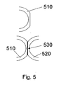
- Figure 5 illustrates the trimming or thinning requirements which may be undertaken in any embodiment in which the coil thickness is equal to any amount greater than one-half of the inter-tube spacing amount (i.e. any embodiment other than the above-described second embodiment).
- the thickness of coil wire 510 it is possible to trim the thickness of coil wire 510 so that it may make planar contact with its neighboring coil wire, for example in Figure 5 , coil wire 520.
- By employing trimming, and thus providing planar contact between coil wires 510 and 520 it is possible to create a larger contact area and thus provide a stronger weld.
- Coil wires should be trimmed down to approximately one-half of the inter-tube space. For example, if the coil thickness of coil wires 510 and 520 were 70% of the inter-tube space, each of coil wires 510 and 520 should be trimmed down to approximately 50% of the inter-tube space at the contact point at weld 530.
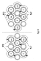
- Figure 6 is an end view of a third embodiment in which the tubes 610 are arranged in triangular pitch. In this case, some tubes 610 will be contained within the interior of coils 620 and others will not. The tubes 610 that are not contained within the interior of individual coils 620 are nonetheless supported by the exterior of the coils 620 around the adjacently disposed tube 610. Again, in this embodiment, it is preferable that coils which are adjacent to one another be wound in opposite directions (i.e. clockwise adjacent to counterclockwise).
- the coil thickness is equal to the inter-tube spacing which results in an overlap as between the adjacent coils when viewed from the end as in the Figure 6 view.
- coil thickness in the triangular pitch case can be anywhere from 50% of inter-tube spacing to 100% of inter-tube spacing. As discussed above, in the case of 50% of inter-tube spacing, the coils will make point contact and not overlap with one another.
- the tubes on the left half of Figure 6 represent the same tubes as is shown on the right half of Figure 6 .
- the tube 610 at the upper left hand corner of the left side coil structure and tubes is the same tube as is shown in the upper left hand corner of the right side coil structure and tubes illustrated in Figure 6 .
- multiple sections of coil structures are interspersed along the length of the tubes 610 with gaps between such coil structures.
- the coil structure it is possible for the coil structure to extend the full length of the tubes without gaps.
- the coil structure be produced such that individual segments with alternating designs are placed end to end to form a coil structure extending the full length of the tubes.
- each successive coil structure along the tube alternate with respect to which tubes are contained within the interior of the coils and which tubes are not.
- the tube at the upper left corner illustrated in the left side of Figure 6 is contained within a coil 610 at one point along the length of the tube while further down the tube, at the next successive coil structure segment (as shown on the right side of Figure 6 ), that same tube is supported by the exterior surfaces of the adjacent coils. It is preferable to form each coil structure so that successive coil structures alternate with respect to which tubes are enclosed internally and which are not as described above.
- a strainer of some form should normally be used at some point in the process line prior to reaching the heat exchanger. This is important in order to avoid any debris becoming trapped within the heat exchanger of the present invention either in a tube or on the shell side of the heat exchanger. If debris of a large enough size or of a large enough amount were to enter the heat exchanger of the present invention (or, in fact, any currently existing heat exchanger) fluid velocities can be reduced to the point of rendering the heat exchanger ineffective.
Landscapes
- Engineering & Computer Science (AREA)
- Physics & Mathematics (AREA)
- Thermal Sciences (AREA)
- Mechanical Engineering (AREA)
- General Engineering & Computer Science (AREA)
- Heat-Exchange Devices With Radiators And Conduit Assemblies (AREA)
Claims (4)
- Echangeur de chaleur (100) comprenant :(a) une pluralité de tubes (230) dans un faisceau de tubes (160) ayant des extrémités opposées en contact avec une plaque tubulaire (180, 190) et espacés suivant un espacement entre les tubes prédéterminé ;(b) une structure de support pour lesdits tubes (230), comprenant une pluralité de bobines de fil (170) en matériau en fil métallique enroulé en hélice, dans laquelle au moins une portion de la longueur des tubes (230) est contenue dans la circonférence interne d'une bobine (170),caractérisé en ce que chaque tube (230) est contenu dans la circonférence intérieure d'une bobine (170) et en ce que le diamètre du fil métallique formant chaque bobine (170) est essentiellement égal à l'espacement entre les tubes, chaque bobine (170) enroulée soit dans une orientation horaire (C) et anti-horaire (CC), les bobines (170) contenant des tubes adjacents (230) étant enveloppées dans une orientation qui est différente de la bobine adjacente (170), et les bobines adjacentes se chevauchant partiellement et venant en contact les unes avec les autres par le biais de soudures (310).
- Echangeur de chaleur selon la revendication 1, dans lequel chaque bobine (170) a essentiellement la même longueur longitudinale que chacun des tubes (230).
- Echangeur de chaleur selon la revendication 1, dans lequel chaque bobine (170) comprend une pluralité de bobines partielles s'étendant le long d'une portion de chacun des tubes (230), les bobines partielles étant positionnées de manière intermittente le long de la longueur du tube (170) avec des espaces entre les bobines partielles.
- Echangeur de chaleur selon la revendication 1, dans lequel chaque bobine (170) est formée de fil métallique avec une section transversale circulaire ou elliptique.
Applications Claiming Priority (4)
| Application Number | Priority Date | Filing Date | Title |
|---|---|---|---|
| US36691402P | 2002-03-22 | 2002-03-22 | |
| US366914P | 2002-03-22 | ||
| US10/209,126 US6874572B2 (en) | 2002-03-22 | 2002-07-31 | Heat exchanger flow-through tube supports |
| US209126 | 2002-07-31 |
Publications (3)
| Publication Number | Publication Date |
|---|---|
| EP1347258A2 EP1347258A2 (fr) | 2003-09-24 |
| EP1347258A3 EP1347258A3 (fr) | 2007-04-25 |
| EP1347258B1 true EP1347258B1 (fr) | 2009-06-24 |
Family
ID=27791370
Family Applications (1)
| Application Number | Title | Priority Date | Filing Date |
|---|---|---|---|
| EP03005710A Expired - Lifetime EP1347258B1 (fr) | 2002-03-22 | 2003-03-13 | Echangeur de chaleur avec supports de tubes |
Country Status (5)
| Country | Link |
|---|---|
| US (1) | US6874572B2 (fr) |
| EP (1) | EP1347258B1 (fr) |
| JP (1) | JP4268818B2 (fr) |
| CA (1) | CA2416970C (fr) |
| DE (1) | DE60328062D1 (fr) |
Families Citing this family (23)
| Publication number | Priority date | Publication date | Assignee | Title |
|---|---|---|---|---|
| JP3796034B2 (ja) | 1997-12-26 | 2006-07-12 | 株式会社ルネサステクノロジ | レベル変換回路および半導体集積回路装置 |
| NO20043150D0 (no) | 2004-07-23 | 2004-07-23 | Ntnu Technology Transfer As | "Fremgangsmate og utstyr for varmegjenvining" |
| US7117935B2 (en) * | 2004-10-12 | 2006-10-10 | Exxonmobil Research And Engineering Company | Support system for tube bundle devices |
| JP2006125654A (ja) * | 2004-10-26 | 2006-05-18 | Matsushita Electric Ind Co Ltd | ヒートポンプ給湯機 |
| EP1907992B1 (fr) | 2005-05-27 | 2010-09-15 | Semiconductor Energy Laboratory Co., Ltd. | Dispositif semi-conducteur |
| US9403204B2 (en) * | 2010-01-29 | 2016-08-02 | Modine Manufacturing Company | Heat exchanger assembly and method |
| US8978740B2 (en) * | 2006-06-22 | 2015-03-17 | Modine Manufacturing Company | Heat exchanger |
| US7670574B2 (en) * | 2007-01-19 | 2010-03-02 | General Electric Company | Methods and apparatus to facilitate cooling syngas in a gasifier |
| DE102009020306A1 (de) * | 2008-05-12 | 2010-02-11 | Modine Manufacturing Co., Racine | Wärmetauscher und Verfahren zum Zusammenbau |
| WO2010107881A1 (fr) * | 2009-03-17 | 2010-09-23 | Dow Global Technologies, Inc. | Appareil échangeur de chaleur à enveloppe et tube à écoulement pulsé séquentiellement côté tube, système et procédé |
| US20120312514A1 (en) * | 2011-06-13 | 2012-12-13 | Erickson Donald C | Dense twisted bundle heat exchanger |
| DE102012012939A1 (de) * | 2012-06-29 | 2014-04-24 | Mann + Hummel Gmbh | Wärmetauscher zur Kühlung eines Fluids einer Brennkraftmaschine, Anordnung mit wenigstens einem Wärmetauscher und Verfahren zur Herstellung eines Wärmetauschers |
| NL2009330C2 (en) * | 2012-08-16 | 2014-02-18 | X Flow Bv | Filter module and filter apparatus containing such filter module. |
| CN103512717A (zh) * | 2013-09-26 | 2014-01-15 | 中国石油集团工程设计有限责任公司 | 大型低温蒸发器在两相流作用下的管束振动预测方法 |
| EP3086075B1 (fr) * | 2015-04-20 | 2020-05-06 | Borgwarner Emissions Systems Spain, S.L.U. | Dispositif d'échange de chaleur |
| CN105674774B (zh) * | 2016-01-29 | 2018-04-06 | 浙江东氟塑料科技有限公司 | 烟气、烟气换热器 |
| CN107588676B (zh) * | 2016-07-06 | 2023-08-15 | 上海长园电子材料有限公司 | 一种换热管的限位装置及换热装置 |
| CN107726895A (zh) * | 2017-10-30 | 2018-02-23 | 佛山科学技术学院 | 异形管孔整圆形支撑板取代弓形折流板的管壳式换热器 |
| CN108007241A (zh) * | 2017-12-14 | 2018-05-08 | 佛山科学技术学院 | 一种折流栅支撑凹面换热管的管壳式换热器 |
| CN108007255A (zh) * | 2017-12-14 | 2018-05-08 | 佛山科学技术学院 | 一种折流栅支撑轴向凹槽换热管的管壳式换热器 |
| CN111141161A (zh) * | 2018-11-06 | 2020-05-12 | 金川集团股份有限公司 | 一种物料换热及回收热能的换热器 |
| CN109443072B (zh) * | 2018-11-16 | 2020-08-25 | 中国舰船研究设计中心 | 一种基于管壳式换热器结构的浮筏隔振装置 |
| CN115900397A (zh) * | 2022-12-30 | 2023-04-04 | 济南岳华节能设备有限公司 | 一种带内置独立冷却器的汽水换热器及方法 |
Family Cites Families (15)
| Publication number | Priority date | Publication date | Assignee | Title |
|---|---|---|---|---|
| US1777356A (en) * | 1927-05-17 | 1930-10-07 | Empire Gas And Fuel Company | Heat-interchange apparatus |
| US1946234A (en) * | 1931-05-19 | 1934-02-06 | Griscom Russell Co | Heat exchanger |
| GB607717A (en) * | 1945-12-13 | 1948-09-03 | Power Jets Res & Dev Ltd | Improvements relating to heat exchangers |
| US2774575A (en) * | 1952-03-07 | 1956-12-18 | Worthington Corp | Regenerator |
| US2749600A (en) * | 1954-02-18 | 1956-06-12 | Rosenblads Patenter Ab | Method of making heat exchangers |
| NL271716A (fr) * | 1960-11-23 | |||
| GB1081498A (en) * | 1965-02-08 | 1967-08-31 | Rosenblads Patenter Ab | Tubular heat exchangers |
| DE1261136B (de) * | 1965-03-31 | 1968-02-15 | Gutehoffnungshuette Sterkrade | Verfahren zum Aufbringen von als Abstandhalter dienenden Wendeln auf Waermetauscherrohre |
| DE1551050A1 (de) * | 1967-03-25 | 1970-02-05 | Siemens Ag | Dampferzeuger,insbesondere fuer Druckwasserkernreaktoren |
| FR2380700A7 (fr) * | 1977-02-11 | 1978-09-08 | Cliref | Perfectionnements a la realisation des faisceaux de tubes pour echangeurs de temperature et autres appareils assurant la mise en contact de deux fluides |
| US4450904A (en) * | 1978-03-31 | 1984-05-29 | Phillips Petroleum Company | Heat exchanger having means for supporting the tubes in spaced mutually parallel relation and suppressing vibration |
| NO148830C (no) * | 1979-10-15 | 1983-12-21 | Cinderella | Anordning til forvarming av vaeske, f.eks. vaeskeformig freon |
| US4428403A (en) * | 1980-12-19 | 1984-01-31 | Extracorporeal Medical Specialties, Inc. | Conduit having spirally wound monofilament material |
| JPS58184498A (ja) | 1982-04-21 | 1983-10-27 | Matsushita Electric Ind Co Ltd | 熱交換器 |
| WO2000065286A1 (fr) | 1999-04-22 | 2000-11-02 | Allan James Yeomans | Absorbeurs d'energie rayonnee |
-
2002
- 2002-07-31 US US10/209,126 patent/US6874572B2/en not_active Expired - Fee Related
-
2003
- 2003-01-22 CA CA2416970A patent/CA2416970C/fr not_active Expired - Fee Related
- 2003-03-10 JP JP2003063537A patent/JP4268818B2/ja not_active Expired - Fee Related
- 2003-03-13 EP EP03005710A patent/EP1347258B1/fr not_active Expired - Lifetime
- 2003-03-13 DE DE60328062T patent/DE60328062D1/de not_active Expired - Lifetime
Also Published As
| Publication number | Publication date |
|---|---|
| CA2416970C (fr) | 2010-08-03 |
| EP1347258A2 (fr) | 2003-09-24 |
| JP2003279288A (ja) | 2003-10-02 |
| DE60328062D1 (de) | 2009-08-06 |
| US20030178187A1 (en) | 2003-09-25 |
| US6874572B2 (en) | 2005-04-05 |
| CA2416970A1 (fr) | 2003-09-22 |
| JP4268818B2 (ja) | 2009-05-27 |
| EP1347258A3 (fr) | 2007-04-25 |
Similar Documents
| Publication | Publication Date | Title |
|---|---|---|
| EP1347258B1 (fr) | Echangeur de chaleur avec supports de tubes | |
| US6736199B2 (en) | Heat exchanger with floating head | |
| US4204570A (en) | Helical spacer for heat exchanger tube bundle | |
| US3610330A (en) | Heat exchanger | |
| CN105209843A (zh) | 用于管壳式热交换器的管束和构造所述管束的方法 | |
| CN107270741B (zh) | 多股流异径管绕管式换热器 | |
| US20120312514A1 (en) | Dense twisted bundle heat exchanger | |
| CN107228581A (zh) | 单股流异径管绕管式换热器 | |
| KR101967273B1 (ko) | 쉘 앤드 튜브 타입 열교환기 | |
| EP1347261B1 (fr) | Echangeur de chaleur à encrassement réduit | |
| US7117935B2 (en) | Support system for tube bundle devices | |
| CN109029052B (zh) | 立式绕管式换热器的管束支撑结构 | |
| CN207147275U (zh) | 多股流异径管绕管式换热器 | |
| US7322403B2 (en) | Heat exchanger with modified tube surface feature | |
| EP3781887B1 (fr) | Appareil d'échange de chaleur et procédé de support de groupe de tubes à l'intérieur d'un échangeur de chaleur | |
| US20150083382A1 (en) | Heat exchanger | |
| CN112082404B (zh) | 换热管、换热器管芯、换热器及制造方法 | |
| JPS6219676B2 (fr) |
Legal Events
| Date | Code | Title | Description |
|---|---|---|---|
| PUAI | Public reference made under article 153(3) epc to a published international application that has entered the european phase |
Free format text: ORIGINAL CODE: 0009012 |
|
| AK | Designated contracting states |
Kind code of ref document: A2 Designated state(s): AT BE BG CH CY CZ DE DK EE ES FI FR GB GR HU IE IT LI LU MC NL PT SE SI SK TR |
|
| AX | Request for extension of the european patent |
Extension state: AL LT LV MK |
|
| PUAL | Search report despatched |
Free format text: ORIGINAL CODE: 0009013 |
|
| AK | Designated contracting states |
Kind code of ref document: A3 Designated state(s): AT BE BG CH CY CZ DE DK EE ES FI FR GB GR HU IE IT LI LU MC NL PT SE SI SK TR |
|
| AX | Request for extension of the european patent |
Extension state: AL LT LV MK |
|
| 17P | Request for examination filed |
Effective date: 20070518 |
|
| 17Q | First examination report despatched |
Effective date: 20070626 |
|
| AKX | Designation fees paid |
Designated state(s): BE DE FR GB IT NL |
|
| GRAP | Despatch of communication of intention to grant a patent |
Free format text: ORIGINAL CODE: EPIDOSNIGR1 |
|
| RTI1 | Title (correction) |
Free format text: HEAT EXCHANGER WITH TUBE SUPPORTS |
|
| GRAS | Grant fee paid |
Free format text: ORIGINAL CODE: EPIDOSNIGR3 |
|
| GRAA | (expected) grant |
Free format text: ORIGINAL CODE: 0009210 |
|
| AK | Designated contracting states |
Kind code of ref document: B1 Designated state(s): BE DE FR GB IT NL |
|
| REG | Reference to a national code |
Ref country code: GB Ref legal event code: FG4D |
|
| REF | Corresponds to: |
Ref document number: 60328062 Country of ref document: DE Date of ref document: 20090806 Kind code of ref document: P |
|
| PLBE | No opposition filed within time limit |
Free format text: ORIGINAL CODE: 0009261 |
|
| STAA | Information on the status of an ep patent application or granted ep patent |
Free format text: STATUS: NO OPPOSITION FILED WITHIN TIME LIMIT |
|
| 26N | No opposition filed |
Effective date: 20100325 |
|
| PGFP | Annual fee paid to national office [announced via postgrant information from national office to epo] |
Ref country code: FR Payment date: 20120328 Year of fee payment: 10 |
|
| PGFP | Annual fee paid to national office [announced via postgrant information from national office to epo] |
Ref country code: GB Payment date: 20120227 Year of fee payment: 10 Ref country code: IT Payment date: 20120316 Year of fee payment: 10 Ref country code: BE Payment date: 20120328 Year of fee payment: 10 |
|
| PGFP | Annual fee paid to national office [announced via postgrant information from national office to epo] |
Ref country code: DE Payment date: 20120330 Year of fee payment: 10 Ref country code: NL Payment date: 20120322 Year of fee payment: 10 |
|
| BERE | Be: lapsed |
Owner name: EXXONMOBIL RESEARCH AND ENGINEERING CY Effective date: 20130331 |
|
| REG | Reference to a national code |
Ref country code: NL Ref legal event code: V1 Effective date: 20131001 |
|
| GBPC | Gb: european patent ceased through non-payment of renewal fee |
Effective date: 20130313 |
|
| REG | Reference to a national code |
Ref country code: FR Ref legal event code: ST Effective date: 20131129 |
|
| REG | Reference to a national code |
Ref country code: DE Ref legal event code: R119 Ref document number: 60328062 Country of ref document: DE Effective date: 20131001 |
|
| PG25 | Lapsed in a contracting state [announced via postgrant information from national office to epo] |
Ref country code: FR Free format text: LAPSE BECAUSE OF NON-PAYMENT OF DUE FEES Effective date: 20130402 Ref country code: GB Free format text: LAPSE BECAUSE OF NON-PAYMENT OF DUE FEES Effective date: 20130313 Ref country code: DE Free format text: LAPSE BECAUSE OF NON-PAYMENT OF DUE FEES Effective date: 20131001 Ref country code: BE Free format text: LAPSE BECAUSE OF NON-PAYMENT OF DUE FEES Effective date: 20130331 |
|
| PG25 | Lapsed in a contracting state [announced via postgrant information from national office to epo] |
Ref country code: IT Free format text: LAPSE BECAUSE OF NON-PAYMENT OF DUE FEES Effective date: 20130313 Ref country code: NL Free format text: LAPSE BECAUSE OF NON-PAYMENT OF DUE FEES Effective date: 20131001 |