EP1347266A2 - Dispositif de mesure d' un objet - Google Patents
Dispositif de mesure d' un objet Download PDFInfo
- Publication number
- EP1347266A2 EP1347266A2 EP03004878A EP03004878A EP1347266A2 EP 1347266 A2 EP1347266 A2 EP 1347266A2 EP 03004878 A EP03004878 A EP 03004878A EP 03004878 A EP03004878 A EP 03004878A EP 1347266 A2 EP1347266 A2 EP 1347266A2
- Authority
- EP
- European Patent Office
- Prior art keywords
- measurement
- measurement object
- optical sensor
- receiver
- light beam
- Prior art date
- Legal status (The legal status is an assumption and is not a legal conclusion. Google has not performed a legal analysis and makes no representation as to the accuracy of the status listed.)
- Granted
Links
Images


Classifications
-
- G—PHYSICS
- G01—MEASURING; TESTING
- G01B—MEASURING LENGTH, THICKNESS OR SIMILAR LINEAR DIMENSIONS; MEASURING ANGLES; MEASURING AREAS; MEASURING IRREGULARITIES OF SURFACES OR CONTOURS
- G01B11/00—Measuring arrangements characterised by the use of optical techniques
- G01B11/002—Measuring arrangements characterised by the use of optical techniques for measuring two or more coordinates
- G01B11/005—Measuring arrangements characterised by the use of optical techniques for measuring two or more coordinates coordinate measuring machines
-
- G—PHYSICS
- G01—MEASURING; TESTING
- G01B—MEASURING LENGTH, THICKNESS OR SIMILAR LINEAR DIMENSIONS; MEASURING ANGLES; MEASURING AREAS; MEASURING IRREGULARITIES OF SURFACES OR CONTOURS
- G01B11/00—Measuring arrangements characterised by the use of optical techniques
- G01B11/02—Measuring arrangements characterised by the use of optical techniques for measuring length, width or thickness
- G01B11/026—Measuring arrangements characterised by the use of optical techniques for measuring length, width or thickness by measuring distance between sensor and object
-
- G—PHYSICS
- G01—MEASURING; TESTING
- G01B—MEASURING LENGTH, THICKNESS OR SIMILAR LINEAR DIMENSIONS; MEASURING ANGLES; MEASURING AREAS; MEASURING IRREGULARITIES OF SURFACES OR CONTOURS
- G01B11/00—Measuring arrangements characterised by the use of optical techniques
- G01B11/24—Measuring arrangements characterised by the use of optical techniques for measuring contours or curvatures
Definitions
- the present invention relates to a device for measuring a measurement object, more precisely the surface of a measurement object, according to the preamble of patent claim 1.
- measuring devices are only for one-dimensional measurement in a coordinate axis (z-axis) as well as for multi-coordinate measurement in the form of 2D or 3D measuring devices, in which in addition to the z coordinate of the measuring point its x and / or y coordinate is also recorded on the measurement object can, known.
- Such a multi-coordinate measuring device is, for example, from DE 38 06 686 A1 known.
- a Multisensor touch systems are both non-contact and mechanically probing Measurement of a measurement object possible.
- the measuring quill of the optical sensor for the non-contact measurement and the mechanical probe for mechanically probing Measurements are on a common or on two separate, in x and Mounted carriage movable in the y coordinate direction.
- the optical sensor has a laser sensor.
- the laser sensor disclosed in DE 38 06 686 A1 follows the surface contour of the Measurement object at a constant distance and thus achieves contour detection in real time with high accuracy and high scanning speed.
- This principle of measurement lies so-called light section method in which the reflective surface of the Target as reference for focusing, i.e. the focus is used.
- the Laser sensor directs a light beam through a lens onto the surface to be measured of the measurement object, from which the light beam reflects and via an optics onto a several differential diodes equipped receiver device is conducted. Because of the in this system, the imaging process migrates from the receiver device received signal when the light beam is defocused on the surface of the measurement object and generates a difference signal, which a feed device is supplied in the form of a servo motor.
- the feed device positions the optical sensor according to the difference signal in the z coordinate direction such that the surface of the measurement object to be measured is again in the Focal plane of the lens is.
- the position of the optical sensor in the z coordinate direction is recorded using a suitable measuring system and fed to an evaluation unit.
- this system is the one determined z coordinate of a measuring point on the measuring object with a so-called lag error afflicted.
- This lag error arises because the mechanical readjustment of the Position of the optical sensor in the z-coordinate direction not exactly at the same time as the Read command from the receiver device, i.e. the receiver device reads one Measured value for the z coordinate, which is not exactly an exact focusing of the measurement object equivalent.
- This error is particularly dependent on the resolution of the measuring system, the scan speed and the geometric errors z-axis.
- the object of the present invention to provide a device for the contactless measurement of a measurement object, in which the following error explained above is avoided or at least clearly is reduced.
- the device for non-contact measurement of a measurement object has an optical sensor, the optical sensor being an optical sensor Pushbuttons (especially laser pushbuttons) with a light source and a measuring lens for Directing a light beam onto a measurement object and a receiver device for Detecting a light beam reflected by the measurement object and generating a corresponding one electronic measurement signal; a feed device for changing the distance between the optical sensor and the measurement object in the z coordinate direction depending on that generated by the receiver device Measuring signal; and an evaluation unit for determining the coordinates of the measuring point on the measurement object.
- Pushbuttons especially laser pushbuttons
- the receiver device with a position sensitive Provide the receiver within a specified measurement window generated by the evaluation unit evaluable measurement signal, and the feed device sets the distance between the optical sensor and the measurement object such that the receiver of the receiver device receives the light beam reflected by the measurement object receives within the measurement window so that the evaluation unit receives the coordinates the measurement point on the measurement object from the position of the optical sensor and the measurement signal generated by the receiver device can be determined.
- the focus of the measurement object must be during a scanning process are not continuously readjusted since the evaluation unit detects the measurement signals can evaluate within the entire measurement window of the receiver device. This eliminates the following error described above, provided that this is from the measurement object reflected light received by the receiver device within the measurement window becomes. Only when the reflected light migrates out of the measuring window does the Focus of the measurement object can be readjusted.
- the measuring device is therefore suitable the invention especially for measuring objects with very flat and flat Surfaces that are common in the semiconductor industry. At one constant High scanning accuracy can significantly increase the scanning speed because the mechanical refocusing of the focusing is completely eliminated or is at least minimized, which leads to significantly reduced measurement times.
- the position-sensitive receiver of the receiver device generates, for example within the measurement window a measurement signal with a linear characteristic with respect to the Receiving position of the reflected light within the programmed measuring window, which can be divided into digital measuring steps in the evaluation unit, from which the measured values can be derived to generate.
- Scan mode is the distance between the optical sensor and the measurement object continuously set such that the receiver of the receiver device is the one of the light beam reflected from the measurement object in the center of gravity within the measurement window receives.
- This operating mode corresponds essentially to that in the beginning described measuring device known from the prior art.
- autofocus single point measurements are also possible, in which the distance between the optical sensor and the measurement object for each measurement point individually is set so that the receiver of the receiver device detects that of the measurement object reflected light beam basically anywhere in the measurement window receives.
- the transmission power of the light source is also preferably dependent on the light intensity of the measurement object received by the receiver device reflected light beam controllable.
- the optical sensor can automatically for example on different reflection properties of the measurement object react and ensure a sufficiently strong reception signal at all times.
- the optical sensor in addition to the explained optical button in the form of a laser button, a video sensor for measuring points on the measurement object.
- the laser button and the video sensor is preferably optionally individually independent of one another can be controlled or used one after the other, combined in any order.
- the video sensor in the optical axis of the focusing device on the same beam path as the laser scanner is set up, i.e. the laser beam of the Laser button and the light of the video sensor through the same measuring lens with the same optical axis and the center of the laser spot on the measurement object is adjusted exactly in the center of the video measuring range and the video sensor always has the same measurement point on the measurement object.
- the measuring device can be a mechanical probe for mechanical have probing detection of measurement points on the measurement object.
- mechanical probes are already well known from the prior art.
- the mechanical probe and the laser probe and the video sensor are preferred of the optical sensor can be controlled independently or alternatively can be controlled in succession in combinations of two or three as a multi-sensor system can be used with each other in any changing order.
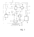
- the optical sensor 10 shown in FIG. 1 for measuring a measurement object 12 or the surface 14 of a measurement object 12 on the measurement device is preferably such attached that it is in the x-y plane, i.e. the plane perpendicular to the drawing plane, can be moved.
- a fixed measuring table for the measurement object 12 shows a relative movement between the optical sensor 10 and the measurement object 12 both in the x-coordinate direction as well as in the y-coordinate direction.
- equivalent to this construction is a measuring device in which the optical sensor 10 is in the x-y plane fixed, but the measuring table is movable in the x-y plane, so that in turn the desired relative movements between the measurement object 12 and the optical sensor 10 are realizable.
- the optical sensor 10 is also by means of a feed device 16, such as of a servo motor, displaceable in the z coordinate direction.
- a feed device 16 such as of a servo motor, displaceable in the z coordinate direction.
- the position of the optical sensor 10 in the z-coordinate direction by means of a suitable measuring device 18 detected and via a signal line a of an evaluation and / or control unit 20 fed.
- An optical device for example, is suitable as the measuring device 18 Measuring system with glass scale or any other position measuring system.
- the optical sensor 10 of the measuring device of FIG. 1 contains a first optical Probe in the form of a laser probe, in particular a light source 22, a measuring lens 24 and a receiver device 26.
- the laser beam reflected at the half mirror 30 28 becomes with appropriately set positioning of the optical sensor 10 through the feed device 16 in the z-coordinate direction through the measurement objective 24 focused on the surface 14 of the measurement object 12.
- the laser beam 28 directed onto the surface 14 of the measurement object 12 is on the latter reflected and again directed in parallel by the measuring lens 24.
- the one on the measurement object 12 reflected light beam 32 then passes the half mirror 30 unhindered and strikes an optic or lens 34. This optic 34 focuses the reflected light beam 32 to a catch area of the receiver device 26.
- the measurement objective 24 is preferably interchangeable is attached to the optical sensor 10, so that depending on the application different measuring lenses with different optical properties are used can be. If necessary, the other optical elements of the optical sensor in their arrangement adapted to the exchanged measuring lens are so that the beam path illustrated in Fig. 1 is guaranteed.
- Differential diodes is the receiver device 26 of the measuring device according to FIG Invention with a position sensitive receiver formed within a programmable measurement window within its capture range by the evaluation unit 20 evaluable measurement signal generated.
- a position sensitive Receiver used within the measurement window depending on the received position of the reflected light beam 32 a measurement signal with linear Characteristic generated with respect to the receiving position.
- the position sensitive For example, the receiver can also be a CCD chip that directly receives digital measurement data generated.
- the receiver device 26 With exact focusing of the surface 14 of the measurement object 12 by the focusing device 24, i.e. with exact positioning of the optical sensor 10 in the z-coordinate direction and thus exact distance between the optical sensor 10 and the measurement object 12, the receiver device 26 receives that from the measurement object 12 reflected light 32 exactly in the center of gravity of the programmed measuring window Receiver device. If the measurement object 12 moves somewhat out of focus, so The light 32 reflected by the measurement object 12 also migrates from the center of gravity of the Measurement window. Due to the special choice of the receiver device 26 with a position-sensitive receiver, the receiver device 26 can transmit a measurement signal generate that is a measure of the deviation of the reception position of the reflected Indicates light 32 from the center of gravity within the measurement window.
- the measurement signal generated in this way is sent via a signal line b to the evaluation and / or Control unit 20 passed.
- the evaluation and / or control unit 20 is such programmed that from the measurement signal supplied to it the extent of the deviation the receiving position of the reflected light 32 within the measurement window of the Can determine the center of gravity of the measurement window of the receiver device 26.
- This evaluation is a linear characteristic of the measurement signal with regard to this position deviation particularly simple and precise.
- the present invention is a matter of course not only on receiver devices 26 with such a linear characteristic limited; for example, characteristic curves with quadratic, logarithmic or the like functionality can be used. From the extent of the position deviation The evaluation and / or control unit 20 then determines the deviation in z coordinate direction from the z position and detected by the measuring device 18 thus the exact z coordinate of the measurement point on the measurement object 12.
- the size of the measurement window and the capture range of the receiver device 26 can either predefined or freely selectable by the user within certain limits or be programmable. Depending on the embodiment of the receiver device 26 and of the optical elements of the optical sensor 10, the size of the measurement window can be one Correspond to the displacement range in the z-coordinate direction of up to 2,000 ⁇ m.
- the receiver device 26 is also via a signal line c to a control unit 38 for the feed device 16 connected in the z-coordinate direction. If the light 32 reflected by the measurement object 12 from the receiver device 26 does not more is received within the specified measurement window, the z-positioning of the optical sensor 10 by a corresponding control signal from the Receiver device 26 are readjusted. In contrast to the ones described at the beginning Conventional measuring devices do not need continuous readjustment focusing so that the following errors described above are avoided or can be at least significantly reduced. This applies in particular to measurement objects 12 with flat or very flat surfaces 14, since readjustments of the Focus are required. Due to the lack of continuous readjustments the scan speed and the accuracy of the measurement are also significantly increased.
- the receiver device 26 is also connected to the light source 22 via a signal line d connected to the laser button. In this way, the transmission power of the light source 22 on the reflectivity of the surface 14 of the measurement object 12 depending on the light intensity of the reflected light received by the receiver device 26 32 are regulated automatically.
- the evaluation and / or control unit 20 processes when determining the z coordinate of the measuring point on the measuring object additional data, such as reflection properties and special material characteristics of the measurement object and characteristics of the optical elements used in the optical sensor 10. Beyond that the evaluation and / or control unit 20 via signal lines e and f to the control unit 38 of the feed device 16, the receiver device 26 and the light source 22 connected to control the operation of the measuring device. Even if this is shown in FIG. 1 is not shown, the evaluation and / or control unit 20 with a Input device 40, a display device (monitor) 42 and an output device (Printer) 44 connected as shown in Figs. 3 and 4 described later is shown.
- the Measuring device in addition to the measurement method described above, in which the focus of the measurement object 12 is only readjusted when scanning, when the reflected light 32 migrates out of the measurement window of the receiver device 26 and which is also referred to here as " 1st scan mode", with the Measuring device according to the present invention also other operating modes, such as the “ 2nd scan mode” and the “ single point measurement” possible.
- the focus of the measurement object 12 is continuously readjusted, similar to the conventional measurement devices.
- the distance between the optical sensor 10 and the measurement object 12, ie the z-positioning of the optical sensor 10 is continuously set such that the receiver of the receiver device 26 receives the light beam 32 reflected by the measurement object 12 in the center of gravity within the programmed measurement window.
- the distance between the optical sensor 10 and the measurement object 12 is set individually for each measurement point in such a way that the receiver of the receiver device 26 receives the light beam 32 reflected by the measurement object at an arbitrary reception position within the programmed measurement window.
- FIG. 2 a second embodiment of a measuring device according to the present invention.
- the measuring device from FIG. 2 essentially differs from the measuring device shown in FIG. 1 in that the optical sensor 10 now also has a video sensor in addition to the laser button having.
- the optical sensor 10 of the second embodiment additionally a camera 46 and one with the evaluation and / or control unit 20 a signal line g connected image processing device 48, the components of the video sensor.
- the video sensor of the optical sensor 10 further includes the semi-transparent mirror 30 inclined by 45 °, measuring objective 24 and optics 50.
- the light 28 emitted by the camera 46 strikes the semitransparent mirror 30 and runs through it to the measuring lens 24.
- the measuring lens 24 focuses the light beam from the camera 46 when the optical sensor is positioned accordingly 10 in the z-coordinate direction on the surface 14 of the measurement object 12 to be measured.
- the light 33 reflected by the measurement object 12 is again through the measurement objective 24 directed parallel and then runs through the 45 ° inclined semitransparent mirror 30 unhindered and then meets the optics or lens 50.
- This optics 50 focuses the reflected light beam 33 onto the camera 46.
- the determination of the individual measurement points of a measurement object 12 to be measured takes place, for example, on the basis of one prepared by the image processing device 48 and a video processor of the evaluation unit 20 digitized gray image of the measurement object section.
- the measuring points are on the outer contour of the measurement object recorded, and the respective contours in the x and y coordinate directions are detected by edge finder routines in the gray image while in the z coordinate direction the measuring points through the determined z coordinates and with the help of the Camera image and / or determined by the laser button.
- the laser scanner of the optical sensor 10 of FIG. 2 points as in the first exemplary embodiment 1 shows a laser light source 22, a semitransparent mirror 30, a measuring lens 24, an optics 34 and a receiver device 26.
- the laser beam 28 of the light source 22 is over the 45 ° inclined, semi-transparent mirror 30 in the beam path of the video sensor mirrored so that the measuring lens 24 from both the laser scanner and the Video sensor with a common optical axis 52 can be used.
- To this Way of the laser scanner and the video sensor of the optical sensor 10 is always the same measurement point is detected on the measurement object 12, so that an offset is compensated between the two sensors in the evaluation and / or control unit 20 is omitted.
- This Structure is already known from DE 38 06 686 A1 and explained in more detail there.
- a half mirror 54 inclined by 45 ° is provided in order to ensure that the measurement object 12 and the semitransparent mirror 30 reflected light 32 in the direction of the optics 34 or the receiver device 26 of the To redirect the laser button.
- a semi-transparent mirror instead of the half mirror 54 shown here a semi-transparent mirror can also be used.
- the operation of the laser probe corresponds to that of the measuring device shown in FIG. 1.
- the receiver device 26 likewise has a position-sensitive receiver with a programmable measurement window and the above-described operating mode " 1st scan mode" can be carried out.
- the laser button and video sensor of the optical sensor 10 of FIG. 2 can be operated either independently of one another or in combination, that is to say they can be operated in succession in any order.
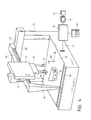
- the measuring device is a measuring machine built in portal construction with a fixed portal, the is formed from two side supports 56, a traverse 58 and a measuring table 60.
- the Traverse 58 also forms the guideway 62 for a cross member 64, which is with a support 66 on a second guideway 68 on the edge of the measuring table 60 supported.
- the cross member 64 is along the two parallel guideways 62 and 68 to against end stops (not shown) in the x coordinate direction above the Measuring table 60 movable.
- the measuring table 60 is, for example, a rotary measuring table trained and fixed in the x-y plane.
- the measuring machine is connected to a signal line 70, which is, for example, the signal lines a to g includes, connected to the evaluation and / or control unit 20.
- a signal line 70 which is, for example, the signal lines a to g includes, connected to the evaluation and / or control unit 20.
- the evaluation and / or control unit 20 With of the evaluation and / or control unit 20 are also an input device 40 for connected to the user, a monitor 42 and a printer 44.
- the control of the Components of the measuring machine and the evaluation of the measurement signals is carried out by the Evaluation and / or control unit 20 in the above with reference to that shown in FIGS. 1 and 2 Embodiments explained way.
- a carriage 72 On the cross member 64 of the measuring machine, a carriage 72 is attached, which along the Cross member 64 is movable in the y coordinate direction.
- This carriage 72 takes two Slidable sleeves 74 and 76 on the z-coordinate direction.
- two separate, movable in the y-coordinate direction provided be, each receiving one of the two quill 74, 76.
- the two sledges can be controlled independently of each other in this case.
- the multi-coordinate measuring device with a measuring table 60 which can be moved in the x-y plane and in the x-y plane fixed quills 64, 76 to provide the same relative movements between the measurement object 12 and the optical sensor 10 and / or the mechanical button 78 are realizable.
- the optical sensor 10 is attached, which in particular according to one of the exemplary embodiments of FIGS. 1 and 2 described above can be built.
- a mechanical probe 78 is attached to the second sleeve 76. This mechanical probe 78 points in order to probe the measurement object 12 known manner on at least one stylus 80 with a stylus ball 82.
- the structure and mode of operation of the mechanical probe are part of the present invention no restrictions.
- the mechanical probe 78 can optionally be independent of the optical sensor 10 controlled or combined with this, i.e. in any changing order to be controlled.
- the Laser probe and the mechanical probe can either be independent of each other or operated in combination.
- the optical sensor 10 of the second Embodiment of Fig. 2 used, the laser button, the video sensor and the mechanical probe either either independently or in any combination of two or three can be combined to create one to ensure great flexibility with regard to the measurement tasks to be accomplished.
- the combined use of the individual sensors or buttons can also be complicated Measurement tasks carried out in a short time and the measurement results of the individual systems be checked against each other.
- FIG. 4 finally shows a fourth exemplary embodiment of a multi-coordinate measuring device according to the present invention.
- buttons or sensors 78, 10 are not attached to two separate quills, but form a single multi-sensor probe that is connected to a common, Adjustable quill 84 is attached in the z-coordinate direction. Even with this design the laser scanner, the video sensor and the mechanical probe can either be used independently of one another or in any combination of two or three be combined.
Landscapes
- Physics & Mathematics (AREA)
- General Physics & Mathematics (AREA)
- Length Measuring Devices By Optical Means (AREA)
- Measurement Of Optical Distance (AREA)
Applications Claiming Priority (2)
| Application Number | Priority Date | Filing Date | Title |
|---|---|---|---|
| DE10211070 | 2002-03-13 | ||
| DE10211070A DE10211070A1 (de) | 2002-03-13 | 2002-03-13 | Vorrichtung zum Vermessen eines Messobjekts |
Publications (3)
| Publication Number | Publication Date |
|---|---|
| EP1347266A2 true EP1347266A2 (fr) | 2003-09-24 |
| EP1347266A3 EP1347266A3 (fr) | 2006-05-31 |
| EP1347266B1 EP1347266B1 (fr) | 2008-04-02 |
Family
ID=27771246
Family Applications (1)
| Application Number | Title | Priority Date | Filing Date |
|---|---|---|---|
| EP03004878A Expired - Lifetime EP1347266B1 (fr) | 2002-03-13 | 2003-03-06 | Dispositif de mesure d' un objet |
Country Status (3)
| Country | Link |
|---|---|
| US (1) | US6927863B2 (fr) |
| EP (1) | EP1347266B1 (fr) |
| DE (2) | DE10211070A1 (fr) |
Cited By (3)
| Publication number | Priority date | Publication date | Assignee | Title |
|---|---|---|---|---|
| CN103557799A (zh) * | 2013-11-20 | 2014-02-05 | 哈尔滨工业大学 | 激光瞬态位移测量装置 |
| CN103760816A (zh) * | 2013-12-30 | 2014-04-30 | 哈尔滨工业大学深圳研究生院 | 基于任务极坐标系的伺服系统轮廓控制方法 |
| DE102008059359B4 (de) * | 2007-12-18 | 2017-10-12 | Disco Corp. | Vorrichtung zum Detektieren der Kanten eines Werkstückes sowie Laserstrahlbearbeitungsmaschine |
Families Citing this family (21)
| Publication number | Priority date | Publication date | Assignee | Title |
|---|---|---|---|---|
| EP1407224B1 (fr) * | 2001-07-16 | 2005-12-28 | Werth Messtechnik GmbH | Procede pour mesurer des proprietes superficielles et dispositif de mesure de coordonnees |
| DE10211760A1 (de) * | 2002-03-14 | 2003-10-02 | Werth Messtechnik Gmbh | Anordnung und Verfahren zum Messen von Geometrien bzw. Strukturen von im Wesentlichen zweidimensionalen Objekten mittels Bildverarbeitungssenorik |
| JP3867230B2 (ja) * | 2002-09-26 | 2007-01-10 | 本田技研工業株式会社 | メカニカルスクライブ装置 |
| US7372581B2 (en) * | 2005-04-11 | 2008-05-13 | Faro Technologies, Inc. | Three-dimensional coordinate measuring device |
| DE102005048134B3 (de) * | 2005-10-06 | 2007-02-08 | Benteler Automobiltechnik Gmbh | Vorrichtung und Verfahren zur optischen Vermessung und/oder Überprüfung von Schweißbaugruppen |
| US20070260420A1 (en) * | 2006-05-03 | 2007-11-08 | Data I/O Corporation | Automated calibration system |
| US7768655B2 (en) * | 2006-12-20 | 2010-08-03 | General Electric Company | Methods and system for measuring an object |
| US7876454B2 (en) * | 2006-12-20 | 2011-01-25 | General Electric Company | Method and system for measurement of a cutting tool |
| CN101275831B (zh) * | 2007-03-26 | 2011-06-22 | 鸿富锦精密工业(深圳)有限公司 | 图像离线处理系统及方法 |
| DE102007019453B4 (de) * | 2007-04-25 | 2012-07-12 | Leica Geosystems Ag | Koordinatenmessgerät mit zwei Schlitten auf gemeinsamer Führung |
| DE102007031346A1 (de) | 2007-07-05 | 2009-01-08 | Carl Mahr Holding Gmbh | Koordinatenmessgerät mit beweglichem Portal |
| DE102008024811A1 (de) * | 2008-05-23 | 2009-11-26 | Volkswagen Ag | Vorrichtung und Verfahren zur Prüfung von Zylinderbohrungen |
| US7924439B2 (en) * | 2008-09-29 | 2011-04-12 | General Electric Company | Method and system for parameter extraction of a cutting tool |
| US10274263B2 (en) * | 2009-04-09 | 2019-04-30 | General Electric Company | Method and apparatus for improved cooling of a heat sink using a synthetic jet |
| US9615482B2 (en) * | 2009-12-11 | 2017-04-04 | General Electric Company | Shaped heat sinks to optimize flow |
| US9478479B2 (en) | 2010-10-26 | 2016-10-25 | General Electric Company | Thermal management system and method |
| US8112172B2 (en) * | 2009-04-29 | 2012-02-07 | General Electric Company | Method and system for gash parameter extraction of a cutting tool |
| JP5870576B2 (ja) * | 2011-09-22 | 2016-03-01 | オムロン株式会社 | 光学計測装置 |
| US11480742B1 (en) * | 2019-11-11 | 2022-10-25 | Apple Inc. | Micro device mass transfer tool |
| DE102021115046A1 (de) | 2021-06-10 | 2022-12-15 | Hans-Georg Grün | Messkopf für ein taktiles Koordinatenmessgerät, Verfahren zum Vermessen eines Werkstücks mit einem taktilen Koordinatenmessgerät sowie Koordinatenmessgerät |
| DE102023131814B3 (de) | 2023-11-15 | 2025-02-20 | Koenig & Bauer Ag | Vorrichtung zum Ausführen von Messaufgaben an einer Oberfläche eines Druckbogens |
Family Cites Families (10)
| Publication number | Priority date | Publication date | Assignee | Title |
|---|---|---|---|---|
| FR2572515B1 (fr) * | 1984-10-25 | 1993-06-18 | Canon Kk | Dispositif de detection de position |
| EP0248479B1 (fr) * | 1986-06-04 | 1991-11-27 | Koninklijke Philips Electronics N.V. | Dispositif de mesure optique d'une distance entre une surface et un plan de référence |
| JPH0652171B2 (ja) * | 1987-02-10 | 1994-07-06 | 株式会社オカダ | 光学式非接触位置測定装置 |
| DE3743363A1 (de) * | 1987-12-21 | 1989-07-06 | Zeiss Carl Fa | Verfahren und einrichtung zur regelung der emissionslichtmenge in einem optischen tastkopf |
| DE3806686A1 (de) * | 1988-03-02 | 1989-09-14 | Wegu Messtechnik | Mehrkoordinatenmess- und -pruefeinrichtung |
| US5251156A (en) * | 1990-08-25 | 1993-10-05 | Carl-Zeiss-Stiftung, Heidenheim/Brenz | Method and apparatus for non-contact measurement of object surfaces |
| ATE137588T1 (de) * | 1990-11-10 | 1996-05-15 | Grosskopf Rudolf Dr Ing | Optische abtastvorrichtung mit konfokalem strahlengang, in der lichtquellen- und detektormatrix verwendet werden |
| DE4109483A1 (de) * | 1991-03-22 | 1992-09-24 | Zeiss Carl Fa | Verfahren und einrichtung zur detektion von kanten und bohrungen mit einem optischen tastkopf |
| DE4327250C5 (de) * | 1992-09-25 | 2008-11-20 | Carl Zeiss Industrielle Messtechnik Gmbh | Verfahren zur Koordinatenmessung an Werkstücken |
| DE4339710C2 (de) * | 1993-11-22 | 1997-02-13 | Univ Schiller Jena | Optoelektronische Abstandsmeßeinrichtung |
-
2002
- 2002-03-13 DE DE10211070A patent/DE10211070A1/de not_active Withdrawn
-
2003
- 2003-03-06 DE DE50309514T patent/DE50309514D1/de not_active Expired - Fee Related
- 2003-03-06 EP EP03004878A patent/EP1347266B1/fr not_active Expired - Lifetime
- 2003-03-11 US US10/386,295 patent/US6927863B2/en not_active Expired - Fee Related
Cited By (4)
| Publication number | Priority date | Publication date | Assignee | Title |
|---|---|---|---|---|
| DE102008059359B4 (de) * | 2007-12-18 | 2017-10-12 | Disco Corp. | Vorrichtung zum Detektieren der Kanten eines Werkstückes sowie Laserstrahlbearbeitungsmaschine |
| CN103557799A (zh) * | 2013-11-20 | 2014-02-05 | 哈尔滨工业大学 | 激光瞬态位移测量装置 |
| CN103760816A (zh) * | 2013-12-30 | 2014-04-30 | 哈尔滨工业大学深圳研究生院 | 基于任务极坐标系的伺服系统轮廓控制方法 |
| CN103760816B (zh) * | 2013-12-30 | 2016-07-13 | 哈尔滨工业大学深圳研究生院 | 基于任务极坐标系的伺服系统轮廓控制方法 |
Also Published As
| Publication number | Publication date |
|---|---|
| EP1347266B1 (fr) | 2008-04-02 |
| US20030184765A1 (en) | 2003-10-02 |
| EP1347266A3 (fr) | 2006-05-31 |
| US6927863B2 (en) | 2005-08-09 |
| DE50309514D1 (de) | 2008-05-15 |
| DE10211070A1 (de) | 2003-09-25 |
Similar Documents
| Publication | Publication Date | Title |
|---|---|---|
| EP1347266B1 (fr) | Dispositif de mesure d' un objet | |
| EP0330901B1 (fr) | Système de mesure et d'essai à plusieurs coordonnées | |
| EP1299691B1 (fr) | Procede de mesure sans contact de la geometrie d'objets | |
| EP3230683B1 (fr) | Machine de mesure de coordonnées et procédés de mesure de caractéristiques sur des pièces | |
| EP2284486B1 (fr) | Appareil de mesure de coordonnées et procédé de mesure à l'aide d'un appareil de mesure de coordonnées | |
| DE102008049821B4 (de) | Abstandssensor und Verfahren zur Ermittlung eines Abstands und/oder von Abstandsschwankungen zwischen einem Bearbeitungslaser und einem Werkstück | |
| DE102015217637C5 (de) | Betreiben eines konfokalen Weißlichtsensors an einem Koordinatenmessgerät und Anordnung | |
| EP2762832B1 (fr) | Mesure optique des points individuels | |
| DE102014108353A1 (de) | Verfahren und Vorrichtung zur Bestimmung von Geometrien an Messobjekten mittels eines kombinierten Sensorsystems | |
| DE202016006669U1 (de) | Optischer Sensor mit variierbaren Messkanälen | |
| DE102015121582A1 (de) | Verfahren und Vorrichtung zur Messung von Merkmalen an Werkstücken | |
| DE112014007223T5 (de) | Abstandssensor, Abstandserfassungsvorrichtung und Abstandserfassungsverfahren | |
| EP3569976B1 (fr) | Tête de mesure de rugosité, dispositif avec ladite tête de mesure et utilisation correspondante | |
| DE102015204796A1 (de) | Koordinatenmessgerät mit beweglichem Sensorträger und Positionsbestimmungseinrichtung, sowie Verfahren zum Betreiben eines Koordinatenmessgeräts | |
| DE102019103519A1 (de) | Vorrichtung zum Bestimmen von dimensionalen und/oder geometrischen Eigenschaften eines Messobjekts | |
| DE19747027A1 (de) | Multisensor-Tasteinrichtung | |
| EP1570234A2 (fr) | Procede pour mesurer un contour d'une piece par balayage | |
| DE102015217332A1 (de) | Positionsmessvorrichtung | |
| DE19816271C1 (de) | Verfahren und Vorrichtung zur Profilbestimmung einer Materialoberfläche | |
| DE4334060A1 (de) | Verfahren und Vorrichtung zur Bestimmung eines Lageparameters einer Meßstelle mittels eines Laserstrahls | |
| DE10337911A1 (de) | Multisensormesskopf für Mehrkoordinatenmess- und -prüfeinrichtungen | |
| DE19954684A1 (de) | Verfahren und Vorrichtung zum Vermessen von Oberflächen eines Messobjektes | |
| EP0092504A2 (fr) | Dispositif de mesure fibre-optique avec un capteur et électronique de mesure pour déterminer une position | |
| EP3855111B1 (fr) | Interféromètre pour l'interférométrie digitale ou holographie digitale, avec un miroir déflecteur | |
| DE10049303A1 (de) | Verfahren zum berührungslosen Messen von Geometrien von Gegenständen |
Legal Events
| Date | Code | Title | Description |
|---|---|---|---|
| PUAI | Public reference made under article 153(3) epc to a published international application that has entered the european phase |
Free format text: ORIGINAL CODE: 0009012 |
|
| AK | Designated contracting states |
Kind code of ref document: A2 Designated state(s): AT BE BG CH CY CZ DE DK EE ES FI FR GB GR HU IE IT LI LU MC NL PT RO SE SI SK TR |
|
| AX | Request for extension of the european patent |
Extension state: AL LT LV MK |
|
| PUAL | Search report despatched |
Free format text: ORIGINAL CODE: 0009013 |
|
| AK | Designated contracting states |
Kind code of ref document: A3 Designated state(s): AT BE BG CH CY CZ DE DK EE ES FI FR GB GR HU IE IT LI LU MC NL PT RO SE SI SK TR |
|
| AX | Request for extension of the european patent |
Extension state: AL LT LV MK |
|
| AKX | Designation fees paid | ||
| 17P | Request for examination filed |
Effective date: 20070207 |
|
| RBV | Designated contracting states (corrected) |
Designated state(s): CH DE FR GB LI |
|
| 17Q | First examination report despatched |
Effective date: 20070328 |
|
| GRAP | Despatch of communication of intention to grant a patent |
Free format text: ORIGINAL CODE: EPIDOSNIGR1 |
|
| GRAS | Grant fee paid |
Free format text: ORIGINAL CODE: EPIDOSNIGR3 |
|
| GRAA | (expected) grant |
Free format text: ORIGINAL CODE: 0009210 |
|
| AK | Designated contracting states |
Kind code of ref document: B1 Designated state(s): CH DE FR GB LI |
|
| REG | Reference to a national code |
Ref country code: GB Ref legal event code: FG4D Free format text: NOT ENGLISH |
|
| REG | Reference to a national code |
Ref country code: CH Ref legal event code: EP |
|
| REF | Corresponds to: |
Ref document number: 50309514 Country of ref document: DE Date of ref document: 20080515 Kind code of ref document: P |
|
| EN | Fr: translation not filed | ||
| PLBE | No opposition filed within time limit |
Free format text: ORIGINAL CODE: 0009261 |
|
| STAA | Information on the status of an ep patent application or granted ep patent |
Free format text: STATUS: NO OPPOSITION FILED WITHIN TIME LIMIT |
|
| 26N | No opposition filed |
Effective date: 20090106 |
|
| PGFP | Annual fee paid to national office [announced via postgrant information from national office to epo] |
Ref country code: GB Payment date: 20090324 Year of fee payment: 7 |
|
| PGFP | Annual fee paid to national office [announced via postgrant information from national office to epo] |
Ref country code: DE Payment date: 20090525 Year of fee payment: 7 |
|
| REG | Reference to a national code |
Ref country code: CH Ref legal event code: PL |
|
| PG25 | Lapsed in a contracting state [announced via postgrant information from national office to epo] |
Ref country code: LI Free format text: LAPSE BECAUSE OF NON-PAYMENT OF DUE FEES Effective date: 20090331 Ref country code: CH Free format text: LAPSE BECAUSE OF NON-PAYMENT OF DUE FEES Effective date: 20090331 |
|
| GBPC | Gb: european patent ceased through non-payment of renewal fee |
Effective date: 20100306 |
|
| PG25 | Lapsed in a contracting state [announced via postgrant information from national office to epo] |
Ref country code: DE Free format text: LAPSE BECAUSE OF NON-PAYMENT OF DUE FEES Effective date: 20101001 |
|
| PG25 | Lapsed in a contracting state [announced via postgrant information from national office to epo] |
Ref country code: GB Free format text: LAPSE BECAUSE OF NON-PAYMENT OF DUE FEES Effective date: 20100306 |
|
| PG25 | Lapsed in a contracting state [announced via postgrant information from national office to epo] |
Ref country code: FR Free format text: LAPSE BECAUSE OF FAILURE TO SUBMIT A TRANSLATION OF THE DESCRIPTION OR TO PAY THE FEE WITHIN THE PRESCRIBED TIME-LIMIT Effective date: 20090123 |