EP1347498A2 - Dispositif d'alignement d'un plateau et procédé de contrôle - Google Patents
Dispositif d'alignement d'un plateau et procédé de contrôle Download PDFInfo
- Publication number
- EP1347498A2 EP1347498A2 EP03250992A EP03250992A EP1347498A2 EP 1347498 A2 EP1347498 A2 EP 1347498A2 EP 03250992 A EP03250992 A EP 03250992A EP 03250992 A EP03250992 A EP 03250992A EP 1347498 A2 EP1347498 A2 EP 1347498A2
- Authority
- EP
- European Patent Office
- Prior art keywords
- moving member
- posture
- controls
- stage
- control section
- Prior art date
- Legal status (The legal status is an assumption and is not a legal conclusion. Google has not performed a legal analysis and makes no representation as to the accuracy of the status listed.)
- Withdrawn
Links
Images




Classifications
-
- H—ELECTRICITY
- H10—SEMICONDUCTOR DEVICES; ELECTRIC SOLID-STATE DEVICES NOT OTHERWISE PROVIDED FOR
- H10P—GENERIC PROCESSES OR APPARATUS FOR THE MANUFACTURE OR TREATMENT OF DEVICES COVERED BY CLASS H10
- H10P76/00—Manufacture or treatment of masks on semiconductor bodies, e.g. by lithography or photolithography
-
- H—ELECTRICITY
- H10—SEMICONDUCTOR DEVICES; ELECTRIC SOLID-STATE DEVICES NOT OTHERWISE PROVIDED FOR
- H10P—GENERIC PROCESSES OR APPARATUS FOR THE MANUFACTURE OR TREATMENT OF DEVICES COVERED BY CLASS H10
- H10P72/00—Handling or holding of wafers, substrates or devices during manufacture or treatment thereof
- H10P72/06—Apparatus for monitoring, sorting, marking, testing or measuring
- H10P72/0612—Production flow monitoring, e.g. for increasing throughput
-
- G—PHYSICS
- G03—PHOTOGRAPHY; CINEMATOGRAPHY; ANALOGOUS TECHNIQUES USING WAVES OTHER THAN OPTICAL WAVES; ELECTROGRAPHY; HOLOGRAPHY
- G03F—PHOTOMECHANICAL PRODUCTION OF TEXTURED OR PATTERNED SURFACES, e.g. FOR PRINTING, FOR PROCESSING OF SEMICONDUCTOR DEVICES; MATERIALS THEREFOR; ORIGINALS THEREFOR; APPARATUS SPECIALLY ADAPTED THEREFOR
- G03F7/00—Photomechanical, e.g. photolithographic, production of textured or patterned surfaces, e.g. printing surfaces; Materials therefor, e.g. comprising photoresists; Apparatus specially adapted therefor
- G03F7/70—Microphotolithographic exposure; Apparatus therefor
- G03F7/70691—Handling of masks or workpieces
- G03F7/70716—Stages
- G03F7/70725—Stages control
-
- G—PHYSICS
- G03—PHOTOGRAPHY; CINEMATOGRAPHY; ANALOGOUS TECHNIQUES USING WAVES OTHER THAN OPTICAL WAVES; ELECTROGRAPHY; HOLOGRAPHY
- G03F—PHOTOMECHANICAL PRODUCTION OF TEXTURED OR PATTERNED SURFACES, e.g. FOR PRINTING, FOR PROCESSING OF SEMICONDUCTOR DEVICES; MATERIALS THEREFOR; ORIGINALS THEREFOR; APPARATUS SPECIALLY ADAPTED THEREFOR
- G03F7/00—Photomechanical, e.g. photolithographic, production of textured or patterned surfaces, e.g. printing surfaces; Materials therefor, e.g. comprising photoresists; Apparatus specially adapted therefor
- G03F7/70—Microphotolithographic exposure; Apparatus therefor
- G03F7/70691—Handling of masks or workpieces
- G03F7/70775—Position control, e.g. interferometers or encoders for determining the stage position
-
- H—ELECTRICITY
- H10—SEMICONDUCTOR DEVICES; ELECTRIC SOLID-STATE DEVICES NOT OTHERWISE PROVIDED FOR
- H10P—GENERIC PROCESSES OR APPARATUS FOR THE MANUFACTURE OR TREATMENT OF DEVICES COVERED BY CLASS H10
- H10P72/00—Handling or holding of wafers, substrates or devices during manufacture or treatment thereof
- H10P72/50—Handling or holding of wafers, substrates or devices during manufacture or treatment thereof for positioning, orientation or alignment
- H10P72/57—Mask-wafer alignment
Definitions
- the present invention relates to a stage alignment apparatus for driving a stage and its control method, exposure apparatus, and semiconductor device manufacturing method.
- the two moving members may thermally expand, each moving member and its motors may be different in parallelism, or the moving member may rotate in the horizontal direction.
- the moving members and stage which can inherently move relative to each other, are likely to excessively constrain each other.
- the moving members and stage fall into this excessive constraint state, they may come in contact with each other to restrict mutual movement, or the alignment precision of the stage may degrade due to vibrations caused by interference between the two moving members.
- the present invention has been made in consideration of the above-mentioned problems, and has as its object to provide a stage alignment apparatus and its control method, exposure apparatus, and semiconductor device manufacturing method by, e.g., controlling the posture of the second moving member on the basis of a signal which controls the posture of the first moving member.
- a stage alignment apparatus characterized by comprising a first moving member which can move in a first direction, a second moving member which can move in a second direction different from the first direction, a stage which is slidably supported by the first moving member and second moving member and is guided in the first and second directions, a first control section which controls a posture, in a third direction different from the first and second directions, of the first moving member, and a second control section which controls a posture, in the third direction, of the second moving member on the basis of a signal which controls the posture of the first moving member.
- each of the first control section and second control section has a measurement section which measures the posture of the moving member, and an actuator which drives the moving member on the basis of a measurement result obtained by the measurement section.
- the actuator comprises a linear motor.
- the second control section controls the posture of the second moving member on the basis of a signal which controls the posture of the first moving member filtered by a predetermined filter.
- the first and second directions are perpendicular to each other, and the third direction is a rotation angle about an axis perpendicular to the first and second directions.
- the first moving member and second moving member are supported by guides arranged such that their ends are parallel to the first and second directions, respectively, and a bearing which slides with a predetermined gap that allows rotational displacement in the third direction with respect to the guides and are guided in the first and second directions through the guides and bearing.
- the first control section performs calculations of a proportional term, integral term, and derivative term to obtain a signal which controls the posture of the first moving member
- the second control section performs calculations of a proportional term and derivative term to obtain the posture of the second moving member
- the first control section controls the posture of the first moving member on the basis of a signal which controls the posture of the second moving member.
- a method of controlling a stage alignment apparatus for guiding a stage in a first direction and a second direction different from the first direction by a first moving member which can move in the first direction and a second moving member which can move in the second direction characterized by comprising the first control step of controlling a posture, in a third direction different from the first and second directions, of the first moving member, and the second control step of controlling the posture in the third direction of the second moving member on the basis of a signal which controls a posture of the first moving member.
- the posture of the first moving member is controlled on the basis of a signal which controls a posture of the second moving member.
- an exposure apparatus characterized in that the exposure apparatus uses a stage alignment apparatus controlled by the above-described control method to transfer a pattern.
- a semiconductor device manufacturing method characterized by comprising the coating step of coating a substrate with a photosensitive member, the exposure step of transferring a pattern onto the substrate coated with the photosensitive member in the coating step using an exposure apparatus as described above, the development step of developing the photosensitive member of the substrate on which the pattern is transferred in the exposure step; and the step of fabricating a semiconductor device from the exposed and developed substrate.
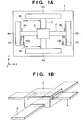
- Figs. 1A and 1B are views showing the schematic arrangement of a stage alignment apparatus according to a preferred embodiment of the present invention.
- Fig. 1A is a plan view of the stage alignment apparatus
- Fig. 1B a perspective view of the stage alignment apparatus.
- the stage alignment apparatus has a surface plate 1, a stage 2 which moves on the surface plate 1 through the surface plate 1 and a bearing (not shown) (e.g., a hydrostatic bearing), a beam-like X moving member 3 which guides the stage 2 in the Y direction, a beam-like Y moving member 4 which guides the stage 2 in the X direction and is substantially perpendicular to the X moving member 3, and a control section which controls the postures (e.g., the rotational displacements, translational displacements, and the like) of the X moving member 3 and Y moving member 4.
- a bearing not shown
- a beam-like X moving member 3 which guides the stage 2 in the Y direction
- a beam-like Y moving member 4 which guides the stage 2 in the X direction and is substantially perpendicular to the X moving member 3
- a control section which controls the postures (e.g., the rotational displacements, translational displacements, and the like) of the X moving member 3 and Y moving member
- the control section includes linear motors 5a and 5b which are arranged at the two ends of the X moving member 3 to drive the X moving member 3 in the X direction, linear motors 6a and 6b which are arranged at the two ends of the Y moving member 4 to drive the Y moving member 4 in the Y direction, Y guides 7a and 7b which guide the Y moving member 4 in the Y direction through hydrostatic pads 8a and 8b, respectively, laser interferometers 9a and 9b which measure the posture (e.g., the displacement in the X direction, the rotational displacement in the ⁇ z direction, and the like) of the X moving member 3, and laser interferometers 10a and 10b which measure the posture (e.g., the displacement in the Y direction, the rotational displacement in the ⁇ z direction, and the like) of the Y moving member 4.
- linear motors 5a and 5b which are arranged at the two ends of the X moving member 3 to drive the X moving member 3 in the X direction
- the stage 2 includes, e.g., the arrangement shown in Fig. 1B.
- the stage 2 is slidably supported by the X moving member 3 and guided along the X moving member 3 to move in the Y direction.
- the stage 2 is also slidably supported by the Y moving member 4 and moves in the X direction along the Y moving member 4.
- the Y moving member 4 with the hydrostatic pads 8a and 8b mounted thereon moves in the Y direction along the Y guides 7a and 7b.
- the Y guides 7a and 7b are fixed on the surface plate 1. Permanent magnets are fixed at the two ends of the X moving member 3, and the X moving member 3 can be driven in the X direction by supplying an electric current to the coils of the linear motors 5a and 5b.
- the Y moving member 4 can rotate in the ⁇ z direction by the gap.
- the X moving member 3 can rotate in the ⁇ z direction by a gap between the stage 2 and the bearing.
- Fig. 2 is a block diagram illustrating the arrangement of a control section which controls the Z-axis rotational displacements of the X moving member 3 and Y moving member 4 in the stage alignment apparatus according to the preferred embodiment of the present invention.
- this control section includes, e.g., a PID controller 11 which performs control calculation such that the Y moving member 4 forms a predetermined target rotation angle ⁇ z0, a PID controller 12 which performs control calculation such that the X moving member 3 forms a predetermined target rotation angle ⁇ z0', amplifiers 13 and 14 which amplify electric currents, and a filter 15 which has a predetermined frequency characteristic.
- a PID controller 11 which performs control calculation such that the Y moving member 4 forms a predetermined target rotation angle ⁇ z0
- PID controller 12 which performs control calculation such that the X moving member 3 forms a predetermined target rotation angle ⁇ z0'
- amplifiers 13 and 14 which amplify electric currents
- a filter 15 which has a predetermined frequency characteristic.
- a rotation angle ⁇ z of the Y moving member 4 is measured by the laser interferometers 10a and 10b.
- the difference between the measured rotation angle ⁇ z and the target rotation angle ⁇ z0 is input to the PID controller 11.
- the PID controller 11 performs control signal calculation (PID calculation) for this input using a proportional term, integral term, and derivative term.
- the amplifier 13 amplifies the output from the PID controller 11.
- the linear motors 6a and 6b drive the Y moving member 4 on the basis of the output from the amplifier 13.
- the rotation angle ⁇ z when the Y moving member 4 is driven is measured by the laser interferometers 10a and 10b, and the measurement result is fed back to the PID controller 11.
- the difference between the rotation angle ⁇ z, which has been measured by the laser interferometers 10a and 10b and the target rotation angle ⁇ z0 is also input to the filter 15.
- the input is subjected to predetermined filtering and calculation (to be described later) and then added to an input to the PID controller 12.
- the rotation angle ⁇ z' of the X moving member 3 is measured by the laser interferometers 9a and 9b.
- the difference between the measured rotation angle ⁇ z' of the X moving member 3 and the target rotation angle ⁇ Z0', and that between the rotation angle ⁇ z of the Y moving member 4 after the predetermined filtering and calculation (to be described later) and the target rotation angle ⁇ z0 are input to the PID controller 12.
- the PID controller 12 performs PID calculation for this input.
- the amplifier 14 amplifies the output from the PID controller 12.
- the linear motors 5a and 5b drive the X moving member 3 on the basis of the output from the amplifier 14.
- the rotation angle ⁇ z' when the X moving member 3 is driven is measured by the laser interferometers 9a and 9b, and the measurement result is fed back to the PID controller 12. In this manner, since the difference between the rotation angle ⁇ z of the Y moving member 4 and the target rotation angle ⁇ z0 is input to the PID controller 12, the X moving member 3 can move in accordance with the control result for the Y moving member 4.
- calculation by the PID controllers 11 and 12 are implemented as software on a computer, the present invention is not limited to this. Part or all of these calculations may be implemented by hardware including at least one of an analog arithmetic element and a digital arithmetic element.
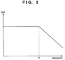
- Fig. 3 is a graph showing a frequency characteristic of the filter 15 shown in Fig. 2.
- the filter 15 is designed to suppress, e.g., frequency components higher than a predetermined frequency f0 of a signal indicating the rotational displacement of the Y moving member 4. This can eliminate extra high-frequency components generated in a signal indicating the rotational displacement of the Y moving member 4 to control the X moving member 3 more precisely.
- Fig. 4 is a graph showing a frequency characteristic of the filter 15, which is different from that shown in Fig. 3.
- the filter 15 can cause the X moving member 3 to track the Y moving member 4 at further higher precision by setting a peak value h1 and a frequency f1 of a frequency response in accordance with the values h1 and f1 of the frequency response of a signal indicating the target rotation angle of the X moving member 3.
- a controller according to the preferred embodiment of the present invention can be implemented at a low cost by software.
- a signal for controlling the posture (e.g., the rotational displacement, translational displacement, and the like) of the first moving member is input to a control system which controls the posture (e.g., the rotational displacement, translational displacement, and the like) of the second moving member to allow a change in tracking performance of the second moving member.
- the frequency response of a filter is set in accordance with the peak value and the frequency of the frequency response in an output signal from the control system which controls the second moving member, so that the second moving member can follow the first moving member further precisely.
- Fig. 5 is a block diagram showing the arrangement of a control section which controls the Z-axis rotational displacements of an X moving member 3 and a Y moving member 4 in a stage alignment apparatus according to the second preferred embodiment of the present invention.
- the same reference numerals denote the parts similar to those in the first embodiment.
- the difference from the first embodiment lies in that a filter 16 with a predetermined frequency characteristic is provided.
- the filter 16 performs predetermined calculation for a signal indicating the difference between a rotation angle ⁇ z' of the X moving member 3 and a target rotation angle ⁇ z0', and the calculation result is added to an input to a PID controller 11.
- stage alignment apparatus An embodiment in which a stage alignment apparatus according to the present invention is applied to an exposure apparatus used in the manufacturing process of a semiconductor device will be described next.
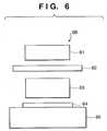
- Fig. 6 shows the concept of an exposure apparatus used when a stage alignment apparatus according to the present invention is applied to the manufacturing process of a semiconductor device.
- An exposure apparatus 60 is comprised of an illumination optical system 61,. a reticle 62, a projection optical system 63, a substrate 64, and a stage 65.
- the illumination optical system 61 can employ, as exposure light, e.g., ultraviolet rays which use an excimer laser, fluorine excimer laser, or the like as a light source.
- Exposure light e.g., ultraviolet rays which use an excimer laser, fluorine excimer laser, or the like as a light source.
- Light emitted from the illumination optical system 61 illuminates the reticle 62.
- the light having passed through the reticle 62 is focused on the substrate 64 through the projection optical system 63 to expose a photosensitive member applied on the substrate 64.
- the substrate 64 is moved to a predetermined position by the stage 65 using the stage alignment apparatus according to the preferred embodiment of the present invention.
- Fig. 7 shows the flow of the whole manufacturing process of the semiconductor device using the above-mentioned exposure apparatus.
- step 1 circuit design
- step 2 mask formation
- step 3 wafer manufacture
- step 4 wafer process
- step 5 assembly
- step 6 post-process
- step 6 the semiconductor device manufactured in step 5 undergoes inspections such as an operation confirmation test and durability test. After these steps, the semiconductor device is completed and shipped (step 7).
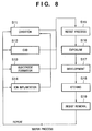
- Fig. 8 shows the detailed flow of the above-mentioned wafer process.
- step 11 oxidation
- step 12 CVD
- step 13 electrode formation
- step 14 ion implantation
- step 15 resist processing
- step 16 exposure
- step 18 etching
- step 18 etching
- step 19 resist removal
- a stage alignment apparatus which precisely moves a stage and its control method, exposure apparatus, and semiconductor device manufacturing method can be provided.
Landscapes
- Physics & Mathematics (AREA)
- General Physics & Mathematics (AREA)
- Exposure And Positioning Against Photoresist Photosensitive Materials (AREA)
- Exposure Of Semiconductors, Excluding Electron Or Ion Beam Exposure (AREA)
- Container, Conveyance, Adherence, Positioning, Of Wafer (AREA)
- Machine Tool Units (AREA)
- Automatic Control Of Machine Tools (AREA)
Applications Claiming Priority (2)
| Application Number | Priority Date | Filing Date | Title |
|---|---|---|---|
| JP2002050289A JP3679767B2 (ja) | 2002-02-26 | 2002-02-26 | ステージ位置決め装置及びその制御方法、露光装置、半導体デバイスの製造方法 |
| JP2002050289 | 2002-02-26 |
Publications (2)
| Publication Number | Publication Date |
|---|---|
| EP1347498A2 true EP1347498A2 (fr) | 2003-09-24 |
| EP1347498A3 EP1347498A3 (fr) | 2004-09-29 |
Family
ID=27784572
Family Applications (1)
| Application Number | Title | Priority Date | Filing Date |
|---|---|---|---|
| EP03250992A Withdrawn EP1347498A3 (fr) | 2002-02-26 | 2003-02-18 | Dispositif d'alignement d'un plateau et procédé de contrôle |
Country Status (6)
| Country | Link |
|---|---|
| US (2) | US6975383B2 (fr) |
| EP (1) | EP1347498A3 (fr) |
| JP (1) | JP3679767B2 (fr) |
| KR (1) | KR100560221B1 (fr) |
| CN (1) | CN1240120C (fr) |
| TW (1) | TWI228206B (fr) |
Cited By (1)
| Publication number | Priority date | Publication date | Assignee | Title |
|---|---|---|---|---|
| EP1494078A1 (fr) * | 2003-07-01 | 2005-01-05 | ASML Netherlands B.V. | Appareil lithographique et méthode de fabrication d'un dispositif |
Families Citing this family (12)
| Publication number | Priority date | Publication date | Assignee | Title |
|---|---|---|---|---|
| JP3679767B2 (ja) * | 2002-02-26 | 2005-08-03 | キヤノン株式会社 | ステージ位置決め装置及びその制御方法、露光装置、半導体デバイスの製造方法 |
| JP4478435B2 (ja) * | 2003-11-17 | 2010-06-09 | キヤノン株式会社 | 露光装置、およびデバイス製造方法 |
| JP4478470B2 (ja) * | 2004-01-26 | 2010-06-09 | キヤノン株式会社 | 位置決めステージ装置 |
| JP2006222312A (ja) * | 2005-02-10 | 2006-08-24 | Canon Inc | ステージ制御装置及びその方法、ステージ装置並びに露光装置 |
| JP4701008B2 (ja) * | 2005-05-25 | 2011-06-15 | 東芝機械株式会社 | ジンバル機構を備えた転写装置 |
| US7782446B2 (en) * | 2007-03-01 | 2010-08-24 | Asml Netherlands B.V. | Stage system and lithographic apparatus comprising such stage system |
| US8285418B2 (en) * | 2009-07-23 | 2012-10-09 | Kla-Tencor Corporation | Dual scanning stage |
| JP5651323B2 (ja) * | 2009-11-09 | 2015-01-07 | 富士機械製造株式会社 | プラズマ処理装置およびプラズマ処理方法 |
| KR101410071B1 (ko) * | 2009-11-09 | 2014-06-25 | 엔에스케이 테쿠노로지 가부시키가이샤 | 마스크 유지 기구 |
| US9864279B2 (en) | 2010-08-05 | 2018-01-09 | Asml Netherlands B.V. | Imprint lithography |
| KR101885749B1 (ko) * | 2013-12-20 | 2018-08-06 | 에이에스엠엘 네델란즈 비.브이. | 리소그래피 장치 및 디바이스 제조 방법 |
| US11720034B2 (en) | 2017-04-11 | 2023-08-08 | Asml Netherlands B.V. | Lithographic apparatus and cooling method |
Family Cites Families (18)
| Publication number | Priority date | Publication date | Assignee | Title |
|---|---|---|---|---|
| US5523843A (en) * | 1990-07-09 | 1996-06-04 | Canon Kabushiki Kaisha | Position detecting system |
| JP2887033B2 (ja) | 1992-11-19 | 1999-04-26 | キヤノン株式会社 | 精密位置決め装置 |
| US5760564A (en) * | 1995-06-27 | 1998-06-02 | Nikon Precision Inc. | Dual guide beam stage mechanism with yaw control |
| US5936710A (en) | 1996-01-05 | 1999-08-10 | Canon Kabushiki Kaisha | Scanning type exposure apparatus, position control apparatus, and method therefor |
| JP3907252B2 (ja) | 1996-12-05 | 2007-04-18 | キヤノン株式会社 | 露光装置およびデバイス製造方法ならびにステージ装置および原点出し方法 |
| JP4146952B2 (ja) * | 1999-01-11 | 2008-09-10 | キヤノン株式会社 | 露光装置およびデバイス製造方法 |
| JP3312297B2 (ja) * | 1999-07-02 | 2002-08-05 | 住友重機械工業株式会社 | ステージ位置制御装置 |
| EP1107067B1 (fr) | 1999-12-01 | 2006-12-27 | ASML Netherlands B.V. | Appareil de positionnement et appareil lithographique muni de celui-ci |
| DE60032568T2 (de) | 1999-12-01 | 2007-10-04 | Asml Netherlands B.V. | Positionierungsapparat und damit versehener lithographischer Apparat |
| EP1111469B1 (fr) | 1999-12-21 | 2007-10-17 | ASML Netherlands B.V. | Appareil lithographique avec un système de positionnement équilibré |
| TWI264617B (en) | 1999-12-21 | 2006-10-21 | Asml Netherlands Bv | Balanced positioning system for use in lithographic apparatus |
| TW546551B (en) | 1999-12-21 | 2003-08-11 | Asml Netherlands Bv | Balanced positioning system for use in lithographic apparatus |
| JP3814453B2 (ja) * | 2000-01-11 | 2006-08-30 | キヤノン株式会社 | 位置決め装置、半導体露光装置およびデバイス製造方法 |
| JP2001284437A (ja) * | 2000-03-30 | 2001-10-12 | Canon Inc | 移動案内装置と移動案内方法及びそれを用いた露光装置 |
| US6593997B1 (en) * | 2000-11-16 | 2003-07-15 | Nikon Corporation | Stage assembly including a reaction assembly |
| US6603531B1 (en) * | 2000-11-16 | 2003-08-05 | Nikon Corporation | Stage assembly including a reaction assembly that is connected by actuators |
| JP2002242983A (ja) | 2001-02-19 | 2002-08-28 | Canon Inc | 能動的除振装置 |
| JP3679767B2 (ja) * | 2002-02-26 | 2005-08-03 | キヤノン株式会社 | ステージ位置決め装置及びその制御方法、露光装置、半導体デバイスの製造方法 |
-
2002
- 2002-02-26 JP JP2002050289A patent/JP3679767B2/ja not_active Expired - Fee Related
-
2003
- 2003-02-18 EP EP03250992A patent/EP1347498A3/fr not_active Withdrawn
- 2003-02-20 US US10/368,621 patent/US6975383B2/en not_active Expired - Fee Related
- 2003-02-24 TW TW092103801A patent/TWI228206B/zh not_active IP Right Cessation
- 2003-02-26 KR KR1020030011989A patent/KR100560221B1/ko not_active Expired - Fee Related
- 2003-02-26 CN CNB031063934A patent/CN1240120C/zh not_active Expired - Fee Related
-
2005
- 2005-07-26 US US11/188,620 patent/US7119879B2/en not_active Expired - Fee Related
Cited By (1)
| Publication number | Priority date | Publication date | Assignee | Title |
|---|---|---|---|---|
| EP1494078A1 (fr) * | 2003-07-01 | 2005-01-05 | ASML Netherlands B.V. | Appareil lithographique et méthode de fabrication d'un dispositif |
Also Published As
| Publication number | Publication date |
|---|---|
| KR20030070854A (ko) | 2003-09-02 |
| US20030164930A1 (en) | 2003-09-04 |
| EP1347498A3 (fr) | 2004-09-29 |
| TW200307189A (en) | 2003-12-01 |
| JP2003249439A (ja) | 2003-09-05 |
| CN1441476A (zh) | 2003-09-10 |
| US6975383B2 (en) | 2005-12-13 |
| US7119879B2 (en) | 2006-10-10 |
| US20060044537A1 (en) | 2006-03-02 |
| JP3679767B2 (ja) | 2005-08-03 |
| TWI228206B (en) | 2005-02-21 |
| CN1240120C (zh) | 2006-02-01 |
| KR100560221B1 (ko) | 2006-03-10 |
Similar Documents
| Publication | Publication Date | Title |
|---|---|---|
| US6570645B2 (en) | Stage system and stage driving method for use in exposure apparatus | |
| US6396566B2 (en) | Stage system for exposure apparatus and device manufacturing method in which a stage supporting member and a countermass supporting member provide vibration isolation | |
| US7443619B2 (en) | Optical element holding apparatus, exposure apparatus and device manufacturing method | |
| US7280185B2 (en) | Stage system including fine-motion cable unit, exposure apparatus, and method of manufacturing device | |
| US6975383B2 (en) | Stage alignment apparatus and its control method, exposure apparatus, and semiconductor device manufacturing method | |
| JP3155936B2 (ja) | リニアモータとステージ装置及びこれを用いた走査型露光装置やデバイス製造方法 | |
| US7586218B2 (en) | Moving apparatus, exposure apparatus, and device manufacturing method | |
| JP3984841B2 (ja) | 歪み計測装置、歪み抑制装置、及び露光装置、並びにデバイス製造方法 | |
| US5574556A (en) | Stage mechanism in exposure apparatus | |
| JP3919592B2 (ja) | ステージ装置及びその制御方法並びに露光装置 | |
| JP4541849B2 (ja) | 位置決め装置 | |
| US7239051B2 (en) | Driving apparatus and exposure apparatus | |
| JP3938110B2 (ja) | 基板受渡機構 | |
| JP2006156554A (ja) | ステージ装置およびそれを用いた露光装置、デバイス製造方法 | |
| JPH09306815A (ja) | 露光装置とこれを利用したデバイス生産方法 |
Legal Events
| Date | Code | Title | Description |
|---|---|---|---|
| PUAI | Public reference made under article 153(3) epc to a published international application that has entered the european phase |
Free format text: ORIGINAL CODE: 0009012 |
|
| AK | Designated contracting states |
Kind code of ref document: A2 Designated state(s): AT BE BG CH CY CZ DE DK EE ES FI FR GB GR HU IE IT LI LU MC NL PT SE SI SK TR |
|
| AX | Request for extension of the european patent |
Extension state: AL LT LV MK RO |
|
| PUAL | Search report despatched |
Free format text: ORIGINAL CODE: 0009013 |
|
| AK | Designated contracting states |
Kind code of ref document: A3 Designated state(s): AT BE BG CH CY CZ DE DK EE ES FI FR GB GR HU IE IT LI LU MC NL PT SE SI SK TR |
|
| AX | Request for extension of the european patent |
Extension state: AL LT LV MK RO |
|
| RIC1 | Information provided on ipc code assigned before grant |
Ipc: 7G 03F 7/20 B Ipc: 7H 01L 21/00 A |
|
| 17P | Request for examination filed |
Effective date: 20050214 |
|
| AKX | Designation fees paid |
Designated state(s): DE IT NL |
|
| 17Q | First examination report despatched |
Effective date: 20050705 |
|
| RIC1 | Information provided on ipc code assigned before grant |
Ipc: H01L 21/68 20060101ALI20140527BHEP Ipc: H01L 21/67 20060101ALI20140527BHEP Ipc: G03F 7/20 20060101AFI20140527BHEP |
|
| GRAP | Despatch of communication of intention to grant a patent |
Free format text: ORIGINAL CODE: EPIDOSNIGR1 |
|
| INTG | Intention to grant announced |
Effective date: 20140704 |
|
| STAA | Information on the status of an ep patent application or granted ep patent |
Free format text: STATUS: THE APPLICATION HAS BEEN WITHDRAWN |
|
| 18W | Application withdrawn |
Effective date: 20141107 |