EP1347703B1 - Laryngoskop - Google Patents
Laryngoskop Download PDFInfo
- Publication number
- EP1347703B1 EP1347703B1 EP01272074A EP01272074A EP1347703B1 EP 1347703 B1 EP1347703 B1 EP 1347703B1 EP 01272074 A EP01272074 A EP 01272074A EP 01272074 A EP01272074 A EP 01272074A EP 1347703 B1 EP1347703 B1 EP 1347703B1
- Authority
- EP
- European Patent Office
- Prior art keywords
- blade
- laryngoscope
- handle
- light source
- mounting means
- Prior art date
- Legal status (The legal status is an assumption and is not a legal conclusion. Google has not performed a legal analysis and makes no representation as to the accuracy of the status listed.)
- Revoked
Links
- 239000011248 coating agent Substances 0.000 claims description 4
- 238000000576 coating method Methods 0.000 claims description 4
- 239000000463 material Substances 0.000 claims description 4
- 238000005286 illumination Methods 0.000 claims description 3
- 238000003384 imaging method Methods 0.000 claims description 2
- 230000006978 adaptation Effects 0.000 abstract 1
- 230000008901 benefit Effects 0.000 description 6
- 238000000926 separation method Methods 0.000 description 5
- 238000003780 insertion Methods 0.000 description 4
- 230000037431 insertion Effects 0.000 description 4
- 230000007246 mechanism Effects 0.000 description 3
- 238000000034 method Methods 0.000 description 3
- 238000004140 cleaning Methods 0.000 description 2
- 239000013536 elastomeric material Substances 0.000 description 2
- 230000000452 restraining effect Effects 0.000 description 2
- 210000003437 trachea Anatomy 0.000 description 2
- 208000003443 Unconsciousness Diseases 0.000 description 1
- 230000004075 alteration Effects 0.000 description 1
- 239000008280 blood Substances 0.000 description 1
- 210000004369 blood Anatomy 0.000 description 1
- 210000001124 body fluid Anatomy 0.000 description 1
- 239000010839 body fluid Substances 0.000 description 1
- 238000011109 contamination Methods 0.000 description 1
- 238000012864 cross contamination Methods 0.000 description 1
- 239000000835 fiber Substances 0.000 description 1
- 208000015181 infectious disease Diseases 0.000 description 1
- 210000000867 larynx Anatomy 0.000 description 1
- 238000012986 modification Methods 0.000 description 1
- 230000004048 modification Effects 0.000 description 1
- 230000008569 process Effects 0.000 description 1
- 210000004872 soft tissue Anatomy 0.000 description 1
- 238000002627 tracheal intubation Methods 0.000 description 1
- 230000000007 visual effect Effects 0.000 description 1
Images



Classifications
-
- A—HUMAN NECESSITIES
- A61—MEDICAL OR VETERINARY SCIENCE; HYGIENE
- A61B—DIAGNOSIS; SURGERY; IDENTIFICATION
- A61B1/00—Instruments for performing medical examinations of the interior of cavities or tubes of the body by visual or photographical inspection, e.g. endoscopes; Illuminating arrangements therefor
- A61B1/267—Instruments for performing medical examinations of the interior of cavities or tubes of the body by visual or photographical inspection, e.g. endoscopes; Illuminating arrangements therefor for the respiratory tract, e.g. laryngoscopes, bronchoscopes
-
- A—HUMAN NECESSITIES
- A61—MEDICAL OR VETERINARY SCIENCE; HYGIENE
- A61B—DIAGNOSIS; SURGERY; IDENTIFICATION
- A61B1/00—Instruments for performing medical examinations of the interior of cavities or tubes of the body by visual or photographical inspection, e.g. endoscopes; Illuminating arrangements therefor
- A61B1/06—Instruments for performing medical examinations of the interior of cavities or tubes of the body by visual or photographical inspection, e.g. endoscopes; Illuminating arrangements therefor with illuminating arrangements
- A61B1/07—Instruments for performing medical examinations of the interior of cavities or tubes of the body by visual or photographical inspection, e.g. endoscopes; Illuminating arrangements therefor with illuminating arrangements using light-conductive means, e.g. optical fibres
Definitions
- the present invention relates to laryngoscopes and relates particularly to laryngoscopes to assist intubation of a tracheal tube.
- Insertion of a tracheal tube is an important procedure in providing an airway to an anaesthetist prior to a surgical operation. Tracheal tubes also often need to be inserted in an emergency situation into the airway of an unconscious patient by paramedics or doctors. Insertion of a tracheal tube requires significant skill, and laryngoscopes are generally used to assist the insertion of the tube by restraining the patient's tongue and allowing a clear view of the larynx and the entrance to the trachea. Considerable skill and care is required in carrying out this procedure in order to avoid damage to the patient's teeth and soft tissue of the throat.
- a known laryngoscope is disclosed in US Patent No 5036835 .
- This known laryngoscope comprises an elongate blade for insertion into the patient's mouth and which is attached in use to a handle extending generally at right angles to the blade such that the blade and handle lie generally in the same plane.
- prior art laryngoscopes are of the type described above in which the blade and handle lie generally in the same plane.
- These known laryngoscopes suffer from the drawback that because the blade and handle occupy the same plane, the user's hand obscures the view into the patient's throat, making the laryngoscope more difficult to use.
- known laryngoscopes are usually stored in a folded condition in which the handle extends generally parallel to the blade. This frequently results in the drawback that blood and other body fluids on the blade come into contact with the handle, causing a risk of cross contamination when the handle subsequently comes into contact with the sterilised blade, thus potentially transferring infection between patients.
- prior art laryngoscopes often require a series of blades of different sizes to accommodate different sizes of patient.
- An object of the present invention is to obviate or mitigate the aforesaid problems.
- a laryngoscope including a handle provided with a blade adapted to be inserted into a patient's mouth, wherein the laryngoscope has mounting means for attaching the blade to the handle, and wherein the mounting means is adapted to slidably and adjustably receive a portion of the blade to provide a desirable working length of blade, and the mounting means offsets the blade with respect to the handle along an axis that is substantially perpendicular to an axis defined by the central length of the handle.
- This invention offers the advantage that the effective length of the blade in use can be adjusted so that a set of separate blades of different lengths is not required.
- the blade in use is gripped by said means for receiving a blade.
- the receiving means for a blade preferably further comprises cam means and a set of jaws for gripping a said blade, wherein movement of the handle about a pivot axis moves said jaws further apart.
- the blade may be gripped by said receiving portion in said folded condition.
- movement of said handle from said at least one orientation into said folded condition moves said jaws closer together.
- the means for receiving a blade is able to receive an elongate blade at a number of different points along the length of the blade.
- the laryngoscope further comprises an image gathering facility.
- the laryngoscope further comprises a viewing means.
- the laryngoscope further comprises illumination means or light source located in said elongate blade
- the laryngoscope further comprises light guide means for directing light from said light source to a location adjacent to the distal end of the elongate blade.
- the laryngoscope further comprises a power supply provided in the body portion for supplying electrical power to said light source, imaging gathering means or viewing means.
- the laryngoscope further comprises a plurality of electrical terminals provided on said blade for connecting said light source, image gathering means or viewing means to said power supply.
- a laryngoscope handle may have a coating of elastomeric and/or polymeric material.
- the laryngoscope preferably further comprises a plurality of electrical terminals provided on at least one said blade for connecting said light source to said power supply.
- the laryngoscope further comprises a camera facility in at least one blade.
- the laryngoscope also comprises a viewing screen.
- the handle may have a coating of elastomeric and/or polymeric material.
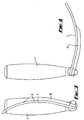
- a laryngoscope 1 has a body portion 2 and a blade 3.
- the body portion 2 includes a handle 4 having a coating of rubber or similar elastomeric and/or polymeric material to enable the handle 4 to be gripped by a user and to be cleaned, and a pair of jaws 5 for receiving the blade 3.
- the jaws 5 are pivotable about axis 6 relative to the handle 4 between a working condition (as shown in Figure 2 ) in which the handle 4 extends generally at right angles to the blade 3 and a folded condition (shown in Figure 1 ) in which the handle 4 extends generally parallel to the blade 3.
- a cam mechanism (not shown) provided on the body portion 2 adjusts the separation of the jaws 5 such that the jaws 5 are further apart when the blade received between the jaws 5 is at an orientation between the working and folded conditions than they are when the handle 4 is in the working or folded condition. The operation of the cam mechanism will be described in greater detail below.
- the blade 3 has an elongate curved surface 7 for restraining the tongue of a patient and providing visual access to the opening of the trachea, and a light source comprising a bulb 8 connected to a series of electrical pick-ups 9 on the edge of the blade 3 and connected via a fibre optic tube 10 to a light outlet 11 near the distal end of the blade 3.
- the blade 3 is adjustably received between jaws 5 such that an electrical pick-up 9 can be aligned with a corresponding electrical terminal (not shown) on the body portion 2 which is in turn connected to a power supply such as a battery located in the handle 4. This enables the light source to illuminate a patient's throat, but the separation of the bulb 8 and outlet 11 avoids burning of the patient's throat by the bulb 8.
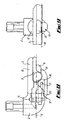
- the jaws 5 comprise an upper clamp arm 12 and a moveable lever 13, the blade 3 being clamped between the underside of the clamp arm 12 and the upper surface of the lever 13.
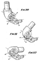
- the clamp arm 12 and lever 13 are pivotably attached to the body portion 2 by means of an interlocking key mechanism 14 having a key surface 15 ( Figures 10 to 12 ) such that the jaws 5 can rotate about axis 6 through a maximum of 90 degrees, i.e., between the working and folded conditions.
- the lever 13 and clamp arm 12 are attached to each other by means of a hook 16 and bar 17, so that the lever 13 can pivot about axis 18 ( Figures 10 to 12 ) relative to clamp arm 12.
- the end 19 of the lever 13 facing the body portion 2 co-operates with a cam surface 20 on the underside of the body portion 2, such that as the handle 4 is rotated relative to the jaws 5, the separation between the end 19 of the lever 13 and the corresponding surface of the clamp arm 12 varies.
- the cam surface 20 is so shaped that when the handle 4 is in the working and folded conditions, the separation between the end 19 of the lever 13 and the corresponding surface of the clamp arm 12 is a maximum, thus causing the jaws 5 to grip the blade 3, while at orientations between the working and folded conditions, the separation between the jaws 5 is sufficient that the position of the blade 3 can be adjusted relative to the body portion 2.
- the blade 3 In its storage (i.e., folded) condition, as shown in Figure 5 , the blade 3 extends generally parallel to the handle 4, but is displaced from the handle in the direction of pivot axis 6. While the laryngoscope is in its folded condition, the blade 3 and handle 4 are sufficiently far apart in the direction of the axis 6 to avoid contact between the handle and the blade. As described above with reference to Figures 8 to 12 , in the folded condition, the jaws 5 are urged towards each other to grip to blade 3.
- the cam surface 20 engaging the end 19 of lever 13 enables the jaws 5 to move sufficiently far apart that the blade 3 can slide in the direction of arrow A in Figure 6 between the jaws 5.
- the blade length is selected such that one of the electrical pick-ups 9 is placed in contact aligned with the electrical terminal provided on the body portion 2 to connect the light source to the power supply in the handle 4, while a length of blade 3 suitable for the size of patient protrudes from the jaws 5.
- handle 4 When the desired working length of blade 3 protrudes from jaws 5, then handle 4 is then rotated in the direction of arrow B shown in Figure 7 about axis 6 until the handle 4 is generally at right angles to the blade 3. As the handle rotates about axis 6, the cam surface 20 causes the jaws 5 to move closer together to hold the blade 3 in the set position. The blade 3 is then held in position, but because the handle 4 is displaced from the blade 3 in the direction of axis 6 as shown in Figure 7 , an unobstructed view into the patient's throat is provided.
- a laryngoscope 1 is provided that has a body portion 2 and blade 3.
- the body portion 2 comprises a receiving jaw portion 5 which is only slightly offset from the handle 4. The slight offset means that the laryngoscope is comfortable in use.
- the laryngoscope 1 may be provided with an image gathering facility and viewing means.
- the viewing means may be attached to the laryngoscope 1, wired to the laryngoscope or completely separate from the laryngoscope.
- the laryngoscope may be designed so that the blade is not gripped in the folded condition.
Landscapes
- Health & Medical Sciences (AREA)
- Life Sciences & Earth Sciences (AREA)
- Surgery (AREA)
- Engineering & Computer Science (AREA)
- Heart & Thoracic Surgery (AREA)
- Pulmonology (AREA)
- Biophysics (AREA)
- Nuclear Medicine, Radiotherapy & Molecular Imaging (AREA)
- Optics & Photonics (AREA)
- Pathology (AREA)
- Radiology & Medical Imaging (AREA)
- Physiology (AREA)
- Otolaryngology (AREA)
- Biomedical Technology (AREA)
- Physics & Mathematics (AREA)
- Medical Informatics (AREA)
- Molecular Biology (AREA)
- Animal Behavior & Ethology (AREA)
- General Health & Medical Sciences (AREA)
- Public Health (AREA)
- Veterinary Medicine (AREA)
- Endoscopes (AREA)
- Eye Examination Apparatus (AREA)
- External Artificial Organs (AREA)
- Polysaccharides And Polysaccharide Derivatives (AREA)
Claims (11)
- Ein Laryngoskop (1) einschließlich eines Griffs (4), der mit einem Spatel (3) versehen ist, welcher angepasst ist, um in den Mund eines Patienten eingeführt zu werden, wobei das Laryngoskop ein Befestigungsmittel (5) zum Anbringen des Spatels an dem Griff aufweist, dadurch gekennzeichnet, dass das Befestigungsmittel angepasst ist, um einen Abschnitt (A) des Spatels verschiebbar und einstellbar zu empfangen, um eine gewünschte Arbeitslänge des Spatels bereitzustellen, und dass das Befestigungsmittel den Spatel mit Bezug auf den Griff entlang einer Achse (6), die zu einer durch die zentrale Länge des Griffs definierten Achse im Wesentlichen senkrecht ist, versetzt.
- Laryngoskop gemäß Anspruch 1, wobei das Befestigungsmittel den Spatel in Verwendung greift.
- Laryngoskop wie in einem der vorhergehenden Ansprüche beschrieben, wobei das Befestigungsmittel zum verschiebbaren und einstellbaren Empfangen eines Spatels angepasst ist, um den Spatel bei einer Anzahl an unterschiedlichen Punkten entlang der Länge des Spatels zu greifen.
- Laryngoskop gemäß einem der vorhergehenden Ansprüche, wobei das Befestigungsmittel zum verschiebbaren und einstellbaren Empfangen eines Spatels eine Reihe von Backen (5) zum Greifen des länglichen Spatels beinhaltet.
- Laryngoskop gemäß einem der vorhergehenden Ansprüche, das ferner eine Bilderfassungsvorrichtung beinhaltet.
- Laryngoskop wie in Anspruch 5 beschrieben, das ferner ein Betrachtungsmittel beinhaltet.
- Laryngoskop gemäß einem der vorhergehenden Ansprüche, das ferner ein Beleuchtungsmittel einschließlich einer Lichtquelle (8) beinhaltet, das in dem Spatel liegt.
- Laryngoskop gemäß Anspruch 7, wobei das Beleuchtungsmittel von dem distalen Ende des länglichen Spatels entfernt liegt, und wobei das Laryngoskop ferner ein Lichtführungsmittel (10) zum Lenken von Licht von der Lichtquelle zu einer Stelle (11) angrenzend an das distale Ende des länglichen Spatels beinhaltet.
- Laryngoskop gemäß einem der vorhergehenden Ansprüche, das ferner eine in einem Körperabschnitt (2) bereitgestellte Stromversorgung beinhaltet, um die Lichtquelle, das Abbildungserfassungsmittel oder das Betrachtungsmittel mit elektrischem Strom zu versorgen.
- Laryngoskop (1) gemäß Anspruch 9, das ferner eine Vielzahl von elektrischen Endstellen beinhaltet, die an dem Spatel bereitgestellt sind, um die Lichtquelle, das Bilderfassungsmittel oder das Betrachtungsmittel mit der Stromversorgung zu verbinden.
- Laryngoskop gemäß einem der vorhergehenden Ansprüche, wobei der Griff (4) eine Beschichtung aus elastomerem und/oder polymerem Material aufweist.
Applications Claiming Priority (3)
| Application Number | Priority Date | Filing Date | Title |
|---|---|---|---|
| GBGB0031621.6A GB0031621D0 (en) | 2000-12-23 | 2000-12-23 | Laryngoscope |
| GB0031621 | 2000-12-23 | ||
| PCT/GB2001/005611 WO2002051304A1 (en) | 2000-12-23 | 2001-12-21 | Laryngoscope |
Publications (2)
| Publication Number | Publication Date |
|---|---|
| EP1347703A1 EP1347703A1 (de) | 2003-10-01 |
| EP1347703B1 true EP1347703B1 (de) | 2008-08-06 |
Family
ID=9905870
Family Applications (1)
| Application Number | Title | Priority Date | Filing Date |
|---|---|---|---|
| EP01272074A Revoked EP1347703B1 (de) | 2000-12-23 | 2001-12-21 | Laryngoskop |
Country Status (8)
| Country | Link |
|---|---|
| US (2) | US20020082478A1 (de) |
| EP (1) | EP1347703B1 (de) |
| AT (1) | ATE403394T1 (de) |
| CA (1) | CA2432897A1 (de) |
| DE (1) | DE60135246D1 (de) |
| ES (1) | ES2312398T3 (de) |
| GB (1) | GB0031621D0 (de) |
| WO (1) | WO2002051304A1 (de) |
Families Citing this family (26)
| Publication number | Priority date | Publication date | Assignee | Title |
|---|---|---|---|---|
| US20010042089A1 (en) * | 1996-01-22 | 2001-11-15 | Tobin William J. | Method and system for customizing marketing services on networks Communicating with hypertext tagging conventions |
| CN100528069C (zh) | 2003-04-29 | 2009-08-19 | 航空医学有限公司 | 具有照相机附装件的喉镜 |
| US8142353B2 (en) | 2004-02-29 | 2012-03-27 | Truphatek International Ltd. | Metal laryngoscope blade with illumination assembly |
| WO2006056976A2 (en) * | 2004-11-23 | 2006-06-01 | Truphatek International Ltd | Handheld penknife-like laryngoscope |
| USD590501S1 (en) * | 2004-11-30 | 2009-04-14 | Aircraft Medical Limited | Laryngoscope handle |
| US10299668B2 (en) * | 2005-10-21 | 2019-05-28 | Physio-Control, Inc. | Laryngoscope with handle-grip activated recording |
| CA2544455A1 (en) * | 2006-04-21 | 2007-10-21 | Garant Gp | Hand tool |
| CA2655378A1 (en) * | 2006-06-20 | 2007-12-27 | Swirl Technologies Pty Ltd | A laryngoscope |
| US20080045801A1 (en) * | 2006-08-15 | 2008-02-21 | M.S. Vision Ltd. | Intubation laryngoscope with detachable blades |
| IL181851A0 (en) * | 2007-03-11 | 2007-07-04 | Truphatek Int Ltd | Laryngoscope handle and accessories therefor |
| CA2625548C (en) | 2007-08-04 | 2012-04-10 | John A. Law | An airway intubation device |
| IL185112A0 (en) * | 2007-08-07 | 2008-01-06 | Truphatek Int Ltd | Laryngoscope apparatus |
| PT2414015T (pt) * | 2009-03-31 | 2021-12-06 | Dilon Tech Inc | Laringoscópio e sistema |
| GB0915107D0 (en) * | 2009-08-28 | 2009-10-07 | Indian Ocean Medical Inc | Laryngoscope |
| CA134823S (en) | 2009-10-02 | 2010-10-25 | Indian Ocean Medical Inc | Laryngoscope with screen |
| US9179831B2 (en) | 2009-11-30 | 2015-11-10 | King Systems Corporation | Visualization instrument |
| US9289114B2 (en) * | 2010-07-30 | 2016-03-22 | Nilesh R. Vasan | Disposable, self-contained laryngoscope and method of using same |
| IL212204A0 (en) | 2011-04-07 | 2011-06-30 | Truphatek Int Ltd | Laryngoscope assembly with enhanced viewing capability |
| CN102525390A (zh) * | 2012-01-20 | 2012-07-04 | 陆惠元 | 便携式麻醉咽喉镜 |
| WO2015033334A1 (en) | 2013-09-03 | 2015-03-12 | Truphatek International Ltd | Single use laryngoscope handle |
| US11166628B2 (en) | 2016-02-02 | 2021-11-09 | Physio-Control, Inc. | Laryngoscope with handle-grip activated recording |
| USD876625S1 (en) | 2018-08-07 | 2020-02-25 | Adroit Surgical, Llc | Laryngoscope |
| CN119488268A (zh) | 2019-03-14 | 2025-02-21 | 泰利福医疗公司 | 通用喉镜窥视片 |
| US20210378499A1 (en) * | 2020-06-05 | 2021-12-09 | Children's Hospital Medical Center Of Akron | Laryngoscope |
| CN118697266B (zh) * | 2024-08-30 | 2024-11-15 | 江苏永乐医疗科技有限公司 | 一种可折叠撑开的麻醉咽喉镜 |
| US12599738B1 (en) * | 2025-04-01 | 2026-04-14 | Joshua Anthony Stramiello | Oral and nasal tracheal intubation assistance device |
Family Cites Families (33)
| Publication number | Priority date | Publication date | Assignee | Title |
|---|---|---|---|---|
| US1908010A (en) * | 1931-06-01 | 1933-05-09 | William J Cameron | Blade holder for tongue depressors |
| US2649087A (en) * | 1951-02-12 | 1953-08-18 | Welch Allyn Inc | Folding laryngoscope and angularly adjustable and detachable joint therefor |
| US3900924A (en) * | 1974-09-16 | 1975-08-26 | Steven D Meltzner | Adjustable oral examination assistance device |
| DE2738202C2 (de) | 1977-08-24 | 1984-03-29 | Heine Optotechnik Gmbh & Co Kg, 8036 Herrsching | Laryngoskop |
| US4213451A (en) * | 1978-08-21 | 1980-07-22 | Swenson Rudolph E | Tongue blade for mouth gag for adults |
| US4384570A (en) * | 1979-01-02 | 1983-05-24 | Roberts James T | Laryngoscope |
| US4337761A (en) * | 1979-11-28 | 1982-07-06 | Upsher Michael S | Laryngoscope |
| US4425909A (en) * | 1982-01-04 | 1984-01-17 | Rieser Michael J | Laryngoscope |
| EP0125687A1 (de) * | 1983-05-17 | 1984-11-21 | GUSTAV MÜLLER GmbH & Co., KG. Fabrik für chirurgische Instrumente | Gerät für medizinische visuelle Untersuchungen von Körperhöhlen oder -gängen mit einem Handgriff |
| US4546762A (en) * | 1983-06-06 | 1985-10-15 | Upsher Michael S | Laryngoscope including a laterally offset blade |
| US4574784A (en) * | 1984-09-04 | 1986-03-11 | Soloway David J | Laryngoscope |
| US4669449A (en) * | 1986-02-18 | 1987-06-02 | Jack Bauman | Submergible laryngoscope metallic housing for fiber optics power source |
| GB8615884D0 (en) * | 1986-06-30 | 1986-08-06 | Yentis S M | Laryngoscopes |
| US5003963A (en) * | 1987-09-28 | 1991-04-02 | James Roger Bullard | Laryngoscope |
| US4947829A (en) * | 1988-05-10 | 1990-08-14 | Bullard James R | Modular blade laryngoscope |
| US5263472A (en) * | 1989-05-26 | 1993-11-23 | Ough Yon D | Laryngoscope blade |
| US5036835A (en) | 1990-04-27 | 1991-08-06 | Mesoud Filli | Adjustable sliding laryngoscope blade |
| US5381787A (en) * | 1990-05-04 | 1995-01-17 | Bullard; James R. | Extendable and retractable laryngoscope |
| US5092314A (en) * | 1990-05-08 | 1992-03-03 | Zeitels Steven M | Adjustable supraglottiscope and methods therefor |
| US5060633A (en) * | 1990-08-31 | 1991-10-29 | Gibson Michael S | Laryngoscope blade |
| US5184603A (en) * | 1991-02-15 | 1993-02-09 | Stone J Gilbert | Automatic intubating laryngoscope |
| US5287848A (en) * | 1991-09-30 | 1994-02-22 | Anthony Cubb | Easy intubator |
| US5645519A (en) * | 1994-03-18 | 1997-07-08 | Jai S. Lee | Endoscopic instrument for controlled introduction of tubular members in the body and methods therefor |
| US5651760A (en) | 1995-03-20 | 1997-07-29 | Upsher Laryngoscope Corporation | Laryngoscope including means for locking the blade in an operative position |
| DE19618291A1 (de) | 1996-05-07 | 1998-01-29 | Storz Karl Gmbh & Co | Instrument mit einem abwinkelbaren Handgriff |
| US5800344A (en) * | 1996-10-23 | 1998-09-01 | Welch Allyn, Inc. | Video laryngoscope |
| US5827178A (en) * | 1997-01-02 | 1998-10-27 | Berall; Jonathan | Laryngoscope for use in trachea intubation |
| US6217512B1 (en) * | 1997-12-12 | 2001-04-17 | Program For Appropriate Technology In Health | Self-illuminated, non-invasive, visual cervical inspection apparatus and method |
| US6123666A (en) * | 1998-04-29 | 2000-09-26 | Vanderbilt University | Laryngoscope blade with fiberoptic scope for remote viewing and method for teaching the proper insertion of a laryngoscope blade into the airway of a patient |
| US6095972A (en) * | 1998-12-18 | 2000-08-01 | Sakamoto; Carl Kaoru | Laryngoscope |
| US6354993B1 (en) * | 1999-06-21 | 2002-03-12 | Karl Storz Gmbh & Co. Kg | Rigid intubating laryngoscope with interchangeable blade and video display |
| GB9917597D0 (en) * | 1999-07-28 | 1999-09-29 | Watson Geoffrey W | Improved laryngoscope |
| US6520909B1 (en) * | 2000-05-16 | 2003-02-18 | Robert C. Rankins | Adjustable tongue blade holder for endoscope |
-
2000
- 2000-12-23 GB GBGB0031621.6A patent/GB0031621D0/en not_active Ceased
-
2001
- 2001-04-06 US US09/827,316 patent/US20020082478A1/en not_active Abandoned
- 2001-12-21 CA CA002432897A patent/CA2432897A1/en not_active Abandoned
- 2001-12-21 ES ES01272074T patent/ES2312398T3/es not_active Expired - Lifetime
- 2001-12-21 WO PCT/GB2001/005611 patent/WO2002051304A1/en not_active Ceased
- 2001-12-21 DE DE60135246T patent/DE60135246D1/de not_active Expired - Lifetime
- 2001-12-21 EP EP01272074A patent/EP1347703B1/de not_active Revoked
- 2001-12-21 AT AT01272074T patent/ATE403394T1/de not_active IP Right Cessation
- 2001-12-21 US US10/451,421 patent/US8740782B2/en not_active Expired - Fee Related
Also Published As
| Publication number | Publication date |
|---|---|
| US20040127770A1 (en) | 2004-07-01 |
| WO2002051304A1 (en) | 2002-07-04 |
| US8740782B2 (en) | 2014-06-03 |
| ATE403394T1 (de) | 2008-08-15 |
| GB0031621D0 (en) | 2001-02-07 |
| EP1347703A1 (de) | 2003-10-01 |
| ES2312398T3 (es) | 2009-03-01 |
| HK1059555A1 (en) | 2004-07-09 |
| US20020082478A1 (en) | 2002-06-27 |
| CA2432897A1 (en) | 2002-07-04 |
| DE60135246D1 (en) | 2008-09-18 |
Similar Documents
| Publication | Publication Date | Title |
|---|---|---|
| EP1347703B1 (de) | Laryngoskop | |
| US5038766A (en) | Blind orolaryngeal and oroesophageal guiding and aiming device | |
| US7946981B1 (en) | Two-piece video laryngoscope | |
| EP0610206B1 (de) | Intubationsvorrichtung | |
| EP1534119B1 (de) | Laryngoskop mit multidirektionalem okular | |
| CN102448361B (zh) | 带有管引导件的喉镜插入区段 | |
| CN102448363B (zh) | 带有侧向管引导件的用于喉镜的插入区段 | |
| EP1307131B1 (de) | Intubationsinstrument | |
| US20050090712A1 (en) | Res-Q-Scope | |
| US7608040B1 (en) | Device to aid in placing tracheal tubes | |
| US12539029B2 (en) | Intubation device | |
| US6090040A (en) | Periscope and retracting laryngoscope for intubation | |
| HK1059555B (en) | Laryngoscope | |
| AU2019295408A1 (en) | Airway manipulator devices | |
| HK1057323B (en) | Intubation instrument | |
| HK1078757B (en) | Laryngoscope with multi-directional eyepiece |
Legal Events
| Date | Code | Title | Description |
|---|---|---|---|
| PUAI | Public reference made under article 153(3) epc to a published international application that has entered the european phase |
Free format text: ORIGINAL CODE: 0009012 |
|
| 17P | Request for examination filed |
Effective date: 20030723 |
|
| AK | Designated contracting states |
Kind code of ref document: A1 Designated state(s): AT BE CH CY DE DK ES FI FR GB GR IE IT LI LU MC NL PT SE TR |
|
| AX | Request for extension of the european patent |
Extension state: AL LT LV MK RO SI |
|
| REG | Reference to a national code |
Ref country code: HK Ref legal event code: DE Ref document number: 1059555 Country of ref document: HK |
|
| RIN1 | Information on inventor provided before grant (corrected) |
Inventor name: MCGRATH, MATTHEW J.R. |
|
| GRAP | Despatch of communication of intention to grant a patent |
Free format text: ORIGINAL CODE: EPIDOSNIGR1 |
|
| GRAS | Grant fee paid |
Free format text: ORIGINAL CODE: EPIDOSNIGR3 |
|
| GRAA | (expected) grant |
Free format text: ORIGINAL CODE: 0009210 |
|
| RAP1 | Party data changed (applicant data changed or rights of an application transferred) |
Owner name: AIRCRAFT MEDICAL LIMITED |
|
| RIN1 | Information on inventor provided before grant (corrected) |
Inventor name: MATHEW JR MCGRATH |
|
| AK | Designated contracting states |
Kind code of ref document: B1 Designated state(s): AT BE CH CY DE DK ES FI FR GB GR IE IT LI LU MC NL PT SE TR |
|
| REG | Reference to a national code |
Ref country code: GB Ref legal event code: FG4D |
|
| REG | Reference to a national code |
Ref country code: CH Ref legal event code: EP |
|
| REG | Reference to a national code |
Ref country code: IE Ref legal event code: FG4D |
|
| REF | Corresponds to: |
Ref document number: 60135246 Country of ref document: DE Date of ref document: 20080918 Kind code of ref document: P |
|
| PG25 | Lapsed in a contracting state [announced via postgrant information from national office to epo] |
Ref country code: AT Free format text: LAPSE BECAUSE OF FAILURE TO SUBMIT A TRANSLATION OF THE DESCRIPTION OR TO PAY THE FEE WITHIN THE PRESCRIBED TIME-LIMIT Effective date: 20080806 Ref country code: FI Free format text: LAPSE BECAUSE OF FAILURE TO SUBMIT A TRANSLATION OF THE DESCRIPTION OR TO PAY THE FEE WITHIN THE PRESCRIBED TIME-LIMIT Effective date: 20080806 |
|
| REG | Reference to a national code |
Ref country code: ES Ref legal event code: FG2A Ref document number: 2312398 Country of ref document: ES Kind code of ref document: T3 |
|
| PG25 | Lapsed in a contracting state [announced via postgrant information from national office to epo] |
Ref country code: BE Free format text: LAPSE BECAUSE OF FAILURE TO SUBMIT A TRANSLATION OF THE DESCRIPTION OR TO PAY THE FEE WITHIN THE PRESCRIBED TIME-LIMIT Effective date: 20080806 |
|
| PG25 | Lapsed in a contracting state [announced via postgrant information from national office to epo] |
Ref country code: DK Free format text: LAPSE BECAUSE OF FAILURE TO SUBMIT A TRANSLATION OF THE DESCRIPTION OR TO PAY THE FEE WITHIN THE PRESCRIBED TIME-LIMIT Effective date: 20080806 |
|
| PLBI | Opposition filed |
Free format text: ORIGINAL CODE: 0009260 |
|
| PG25 | Lapsed in a contracting state [announced via postgrant information from national office to epo] |
Ref country code: PT Free format text: LAPSE BECAUSE OF FAILURE TO SUBMIT A TRANSLATION OF THE DESCRIPTION OR TO PAY THE FEE WITHIN THE PRESCRIBED TIME-LIMIT Effective date: 20090106 |
|
| PLAX | Notice of opposition and request to file observation + time limit sent |
Free format text: ORIGINAL CODE: EPIDOSNOBS2 |
|
| REG | Reference to a national code |
Ref country code: HK Ref legal event code: GR Ref document number: 1059555 Country of ref document: HK |
|
| 26 | Opposition filed |
Opponent name: VERATHON MEDICAL (CANADA) ULC Effective date: 20090506 |
|
| PG25 | Lapsed in a contracting state [announced via postgrant information from national office to epo] |
Ref country code: MC Free format text: LAPSE BECAUSE OF NON-PAYMENT OF DUE FEES Effective date: 20081231 |
|
| REG | Reference to a national code |
Ref country code: CH Ref legal event code: PL |
|
| NLR1 | Nl: opposition has been filed with the epo |
Opponent name: VERATHON MEDICAL (CANADA) ULC |
|
| PLAF | Information modified related to communication of a notice of opposition and request to file observations + time limit |
Free format text: ORIGINAL CODE: EPIDOSCOBS2 |
|
| PG25 | Lapsed in a contracting state [announced via postgrant information from national office to epo] |
Ref country code: LI Free format text: LAPSE BECAUSE OF NON-PAYMENT OF DUE FEES Effective date: 20081231 Ref country code: CH Free format text: LAPSE BECAUSE OF NON-PAYMENT OF DUE FEES Effective date: 20081231 |
|
| PLAF | Information modified related to communication of a notice of opposition and request to file observations + time limit |
Free format text: ORIGINAL CODE: EPIDOSCOBS2 |
|
| PG25 | Lapsed in a contracting state [announced via postgrant information from national office to epo] |
Ref country code: SE Free format text: LAPSE BECAUSE OF FAILURE TO SUBMIT A TRANSLATION OF THE DESCRIPTION OR TO PAY THE FEE WITHIN THE PRESCRIBED TIME-LIMIT Effective date: 20081106 |
|
| PGFP | Annual fee paid to national office [announced via postgrant information from national office to epo] |
Ref country code: ES Payment date: 20091218 Year of fee payment: 9 Ref country code: IE Payment date: 20091215 Year of fee payment: 9 |
|
| PLBB | Reply of patent proprietor to notice(s) of opposition received |
Free format text: ORIGINAL CODE: EPIDOSNOBS3 |
|
| PGFP | Annual fee paid to national office [announced via postgrant information from national office to epo] |
Ref country code: NL Payment date: 20090612 Year of fee payment: 9 |
|
| PGFP | Annual fee paid to national office [announced via postgrant information from national office to epo] |
Ref country code: IT Payment date: 20091224 Year of fee payment: 9 |
|
| PG25 | Lapsed in a contracting state [announced via postgrant information from national office to epo] |
Ref country code: LU Free format text: LAPSE BECAUSE OF NON-PAYMENT OF DUE FEES Effective date: 20081221 Ref country code: CY Free format text: LAPSE BECAUSE OF FAILURE TO SUBMIT A TRANSLATION OF THE DESCRIPTION OR TO PAY THE FEE WITHIN THE PRESCRIBED TIME-LIMIT Effective date: 20080806 |
|
| PG25 | Lapsed in a contracting state [announced via postgrant information from national office to epo] |
Ref country code: TR Free format text: LAPSE BECAUSE OF FAILURE TO SUBMIT A TRANSLATION OF THE DESCRIPTION OR TO PAY THE FEE WITHIN THE PRESCRIBED TIME-LIMIT Effective date: 20080806 |
|
| PG25 | Lapsed in a contracting state [announced via postgrant information from national office to epo] |
Ref country code: GR Free format text: LAPSE BECAUSE OF FAILURE TO SUBMIT A TRANSLATION OF THE DESCRIPTION OR TO PAY THE FEE WITHIN THE PRESCRIBED TIME-LIMIT Effective date: 20081107 |
|
| PGFP | Annual fee paid to national office [announced via postgrant information from national office to epo] |
Ref country code: FR Payment date: 20110110 Year of fee payment: 10 |
|
| REG | Reference to a national code |
Ref country code: DE Ref legal event code: R064 Ref document number: 60135246 Country of ref document: DE Ref country code: DE Ref legal event code: R103 Ref document number: 60135246 Country of ref document: DE |
|
| PGFP | Annual fee paid to national office [announced via postgrant information from national office to epo] |
Ref country code: GB Payment date: 20101223 Year of fee payment: 10 |
|
| RDAF | Communication despatched that patent is revoked |
Free format text: ORIGINAL CODE: EPIDOSNREV1 |
|
| PGFP | Annual fee paid to national office [announced via postgrant information from national office to epo] |
Ref country code: DE Payment date: 20110103 Year of fee payment: 10 |
|
| REG | Reference to a national code |
Ref country code: NL Ref legal event code: V1 Effective date: 20110701 |
|
| RDAG | Patent revoked |
Free format text: ORIGINAL CODE: 0009271 |
|
| STAA | Information on the status of an ep patent application or granted ep patent |
Free format text: STATUS: PATENT REVOKED |
|
| 27W | Patent revoked |
Effective date: 20110302 |
|
| GBPR | Gb: patent revoked under art. 102 of the ep convention designating the uk as contracting state |
Effective date: 20110302 |
|
| REG | Reference to a national code |
Ref country code: DE Ref legal event code: R107 Ref document number: 60135246 Country of ref document: DE Effective date: 20111117 |
|
| PG25 | Lapsed in a contracting state [announced via postgrant information from national office to epo] |
Ref country code: IT Free format text: LAPSE BECAUSE OF NON-PAYMENT OF DUE FEES Effective date: 20101221 |
|
| PG25 | Lapsed in a contracting state [announced via postgrant information from national office to epo] |
Ref country code: ES Free format text: LAPSE BECAUSE OF NON-PAYMENT OF DUE FEES Effective date: 20101222 |