EP1348333A2 - Outil de traite - Google Patents
Outil de traite Download PDFInfo
- Publication number
- EP1348333A2 EP1348333A2 EP03076788A EP03076788A EP1348333A2 EP 1348333 A2 EP1348333 A2 EP 1348333A2 EP 03076788 A EP03076788 A EP 03076788A EP 03076788 A EP03076788 A EP 03076788A EP 1348333 A2 EP1348333 A2 EP 1348333A2
- Authority
- EP
- European Patent Office
- Prior art keywords
- liner
- teat cup
- milking
- milking member
- filling material
- Prior art date
- Legal status (The legal status is an assumption and is not a legal conclusion. Google has not performed a legal analysis and makes no representation as to the accuracy of the status listed.)
- Withdrawn
Links
Images


Classifications
-
- A—HUMAN NECESSITIES
- A01—AGRICULTURE; FORESTRY; ANIMAL HUSBANDRY; HUNTING; TRAPPING; FISHING
- A01J—MANUFACTURE OF DAIRY PRODUCTS
- A01J5/00—Milking machines or devices
- A01J5/04—Milking machines or devices with pneumatic manipulation of teats
- A01J5/08—Teat-cups with two chambers
Definitions
- the invention relates to a milking member according to the preamble of claim 1.
- the invention further relates to a milking robot provided with such a milking member.
- Such a milking member is known.
- the filling material consists predominantly of a soft material, such as foam rubber or a soft synthetic material. According to a still further inventive feature, the filling material is porous.
- the milking member can be applied in a very advantageous manner in an automatic milking implement or milking robot in which, of course, milking members are used intensively and almost continuously.
- the prevention of wear is of major importance in such an implement.
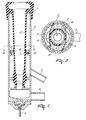
- FIG. 1 shows a schematic longitudinal section of a first embodiment of the milking member according to the invention.
- the milking member comprises a teat cup 1 for collecting and conveying the milk yielded, which teat cup 1 consists e.g. of metal or synthetic material and whose inner side is provided with a liner 2 whose upper side is connected to the teat cup 1 via a nozzle 3.
- the teat cup 1 is connected to a milk line 4 in which there is a permanent vacuum. Via this vacuum line 4 the milk is discharged from the teat cup 1 in order to be processed further.
- a pulsation line 5 is also connected to the teat cup 1 and is adapted to realize changes in pressure in the space between the outer wall of the teat cup 1 and the liner 2, by means of which at milking the flexible, deformable liner 2 repeatedly collapses or is squeezed in a release phase and is reopened in a subsequent suction phase.
- the teat cup 1 is further connected to a non-shown milking cluster or a robot arm via positioning means 6 known per se.
- the liner 2 is e.g. made of rubber and is substantially cylindrical or slightly conical.
- kinking points or places i.e. parts of the liner 2 where a sharp twist or bend in the material is formed.
- the milking member is provided with means for influencing the positions on the circumference of the liner 2 of kinking places which are formed in the liner 2 when it is squeezed.
- the positions of the kinking points which are formed on the circumference of the liner 2 when it is squeezed can be altered. Altering each time the positions of the kinking places (i.e. changing the direction in which the liner 2 is squeezed) prevents the kinking places from being formed each time at the same spots.
- Figure 2 is a schematic cross section of the milking member of Figure 1 taken on the line II - II.
- the means comprise a disc 7 which is provided in its centre with an oval or elongated aperture.
- the means are further adapted to rotate said disc 7 periodically.
- the means comprise a toothing 8 that is rigidly connected to the teat cup 1, as well as at least one pushing element 9 that is connected to the disc 7 and cooperates with the toothing 8.
- the pushing elements 9 are each constituted by a resilient pin or strip (such as a leaf spring) , whose one end is connected to the disc 7 and whose other end extends into the toothing 8.
- the pin or strip 9 is adapted, at squeezing of the liner 2, to be deformed by said liner substantially perpendicular to the longitudinal direction of the pin or strip and thus to be put under tension. From the position of Figure 2, when being squeezed the liner 2 will bulge to the left and the right, so that the pushing elements 9 will be somewhat more curved and thus slightly be put under tension, while the end extending into the toothing 8 each time moves up a tine. When subsequently the liner reassumes the form and position shown in Figure 2, the pin or strip 9 will release, so that the disc 7 is rotated somewhat in the direction of the arrow shown in Figure 2. In a next suction phase the process is repeated, so that the disc 7 is each time rotated further. Of course, the oval aperture in the disc 7 rotates along, so that the direction in which the liner 2 is allowed to bulge each time changes. Around its central aperture the disc 7 is furthermore provided with apertures 10 for air transmission.
- the positions of the kinking places in the liner 2 are altered periodically (each time before a suction phase). In this manner not only the load of the material of the liner 2 is spread efficiently, but milking a teat will also entail a stimulating, massaging effect because the teat is slightly squeezed by the liner 2, each time from an other direction.
- FIG 3 is a schematic longitudinal section of a second embodiment according to the invention of the milking member and Figure 4 is a schematic cross section of the milking member of Figure 3 taken on the line IV - IV.
- the disc 7 provided with an oval aperture again comprises two pushing elements 9 which are now each constituted by a casing fixed on the disc 7 and accommodating a closed bellows or balloon 11 one end of which is provided with a slightly resilient pin or strip (such as a leaf spring) whose end extends into the toothing 8 that is rigidly connected to the teat cup 1.
- the bellows 11 is adapted to move the pin or strip substantially in longitudinal direction under the influence of the changes in pressure caused by the pulsation line 5. From the position shown in Figure 4, at increasing the pressure with the aid of the pulsation line 5, not only the liner 2 will collapse, but the bellows 11 will withdraw the pin or strip 9 whose end will be inserted into a next tine of the toothing 8 because of the slightly resilient effect of the pin or strip. When, at decreasing the pressure the liner 2 subsequently reassumes the form and position shown in Figure 4, the pressure in the bellows 11 will ensure that the pin or strip 9 will be stretched out again, so that the disc 7 is rotated somewhat in the direction of the arrow shown in Figure 4.
- the space between the outer wall of the teat cup 1 and the liner 2 can partially be filled with a filling material 12. Consequently the amount of fluid required for the increase and decrease of pressure is smaller, so that a smaller pulsation line 5 will suffice.
- the filling material 12 consists substantially of a soft material, such as foam rubber or a soft synthetic material.
- the filling material 12 may also be porous.
- Figure 5 is a schematic longitudinal section of a third embodiment of the milking member and Figure 6 is a schematic cross section of the milking member of Figure 5 taken on the line VI - VI.
- the means comprise an intermediate casing 14 which is rotatably bearing-supported in the teat cup 1 with the aid of bearings 13 and which is rotatable as a whole, e.g. by means of a (non-shown) cleaning device which is connectable to the nozzle 3 of the teat cup 1.
- the intermediate casing 14 is provided on all sides with apertures 15, so that the space between the liner 2 and the intermediate casing 14 is constantly in connection with the pulsation line 5.
- the liner 2 is rotated as a whole at each cleaning run, so that the position of the kinking places which are formed is influenced.
- the space between the intermediate casing 14 and the liner 2 can partially be filled with a filling material 12.
- FIG. 7 is a schematic cross section of a fourth embodiment of the milking member. In this embodiment it is possible to determine at random where the kinking places of the liner 2 will be formed.
- a teat cup 1 which roughly equals the teat cup 1 represented in Figure 3.
- the teat cup 1 comprises a bearing edge 16 on which a disc 7 provided with an oval aperture is rotatably disposed.
- the disc 7 comprises a toothing 8 that engages with a gear wheel of a motor 17 and is rigidly connected to the liner of the teat cup 1.
- the motor 17 can be designed e.g. as an electric motor or a pneumatic motor.
- a value by means of a (non-shown) random generator, which value corresponds to a certain period of time during which the motor 17 is energized.
- the disc 7 will undergo a certain angular rotation.
- the value each time being determined at random it is never certain where the kinking places of the liner 2 will be formed. With the latter measure it is achieved that the animal does not get accustomed to a certain rhythm in the formation of the kinking places. Determining the kinking place at random has the advantage that the teat is additionally stimulated.
Landscapes
- Life Sciences & Earth Sciences (AREA)
- Animal Husbandry (AREA)
- Environmental Sciences (AREA)
- External Artificial Organs (AREA)
Applications Claiming Priority (3)
| Application Number | Priority Date | Filing Date | Title |
|---|---|---|---|
| NL1008671A NL1008671C2 (nl) | 1998-03-23 | 1998-03-23 | Melkorgaan. |
| NL1008671 | 1998-03-23 | ||
| EP99200604A EP0945056B1 (fr) | 1998-03-23 | 1999-03-03 | Outil de traite |
Related Parent Applications (1)
| Application Number | Title | Priority Date | Filing Date |
|---|---|---|---|
| EP99200604A Division EP0945056B1 (fr) | 1998-03-23 | 1999-03-03 | Outil de traite |
Publications (2)
| Publication Number | Publication Date |
|---|---|
| EP1348333A2 true EP1348333A2 (fr) | 2003-10-01 |
| EP1348333A3 EP1348333A3 (fr) | 2003-11-19 |
Family
ID=19766790
Family Applications (2)
| Application Number | Title | Priority Date | Filing Date |
|---|---|---|---|
| EP99200604A Expired - Lifetime EP0945056B1 (fr) | 1998-03-23 | 1999-03-03 | Outil de traite |
| EP03076788A Withdrawn EP1348333A3 (fr) | 1998-03-23 | 1999-03-03 | Outil de traite |
Family Applications Before (1)
| Application Number | Title | Priority Date | Filing Date |
|---|---|---|---|
| EP99200604A Expired - Lifetime EP0945056B1 (fr) | 1998-03-23 | 1999-03-03 | Outil de traite |
Country Status (4)
| Country | Link |
|---|---|
| EP (2) | EP0945056B1 (fr) |
| AT (1) | ATE252819T1 (fr) |
| DE (1) | DE69912337T2 (fr) |
| NL (1) | NL1008671C2 (fr) |
Cited By (2)
| Publication number | Priority date | Publication date | Assignee | Title |
|---|---|---|---|---|
| AU2008202821B2 (en) * | 2008-01-17 | 2010-07-01 | Richard Paul Wallace | Teat Cup Assembly |
| RU2647877C1 (ru) * | 2017-03-29 | 2018-03-21 | Федеральное государственное бюджетное образовательное учреждение высшего образования "Калмыцкий государственный университет имени Б.Б. Городовикова" | Доильный стакан |
Families Citing this family (3)
| Publication number | Priority date | Publication date | Assignee | Title |
|---|---|---|---|---|
| SE512852C2 (sv) * | 1998-09-04 | 2000-05-22 | Alfa Laval Agri Ab | Spenkopp för mjölkning av kor eller andra djur |
| DE10143086A1 (de) * | 2001-09-03 | 2003-03-20 | Bayer Cropscience Ag | Verwendung von Calciumformiat in Pflanzenbehandlungsmitteln |
| US10285378B2 (en) * | 2016-01-28 | 2019-05-14 | Technologies Holdings Corp. | Milking cup with rotating shell |
Family Cites Families (4)
| Publication number | Priority date | Publication date | Assignee | Title |
|---|---|---|---|---|
| US3874338A (en) * | 1972-10-09 | 1975-04-01 | Fritz Happel | Milking cup |
| DE2720856A1 (de) * | 1977-05-09 | 1978-11-23 | Fritz Happel | Verfahren und vorrichtung zum maschinellen melken |
| US4315480A (en) * | 1980-06-30 | 1982-02-16 | Noorlander Daniel O | Teat cups for milking machines |
| NL9101636A (nl) * | 1991-09-27 | 1993-04-16 | Lely Nv C Van Der | Werkwijze voor het automatisch melken van dieren. |
-
1998
- 1998-03-23 NL NL1008671A patent/NL1008671C2/nl not_active IP Right Cessation
-
1999
- 1999-03-03 EP EP99200604A patent/EP0945056B1/fr not_active Expired - Lifetime
- 1999-03-03 DE DE69912337T patent/DE69912337T2/de not_active Expired - Lifetime
- 1999-03-03 AT AT99200604T patent/ATE252819T1/de not_active IP Right Cessation
- 1999-03-03 EP EP03076788A patent/EP1348333A3/fr not_active Withdrawn
Cited By (3)
| Publication number | Priority date | Publication date | Assignee | Title |
|---|---|---|---|---|
| AU2008202821B2 (en) * | 2008-01-17 | 2010-07-01 | Richard Paul Wallace | Teat Cup Assembly |
| AU2008202821C1 (en) * | 2008-01-17 | 2010-10-28 | Richard Paul Wallace | Teat Cup Assembly |
| RU2647877C1 (ru) * | 2017-03-29 | 2018-03-21 | Федеральное государственное бюджетное образовательное учреждение высшего образования "Калмыцкий государственный университет имени Б.Б. Городовикова" | Доильный стакан |
Also Published As
| Publication number | Publication date |
|---|---|
| ATE252819T1 (de) | 2003-11-15 |
| EP0945056A3 (fr) | 2000-01-19 |
| NL1008671C2 (nl) | 1999-09-24 |
| EP0945056B1 (fr) | 2003-10-29 |
| EP0945056A2 (fr) | 1999-09-29 |
| DE69912337T2 (de) | 2004-06-24 |
| EP1348333A3 (fr) | 2003-11-19 |
| DE69912337D1 (de) | 2003-12-04 |
Similar Documents
| Publication | Publication Date | Title |
|---|---|---|
| CA1289502C (fr) | Dispositif d'expansion pour trayeuse | |
| US3659558A (en) | Teat cup inflation | |
| CA1146108A (fr) | Coupelles de machine a traire | |
| EP1549134B1 (fr) | Tuyau court à lait | |
| US6308656B1 (en) | Modular teat cup assembly | |
| US3967587A (en) | Teat cup inflation | |
| EP0935916A1 (fr) | Manchon trayeur | |
| EP1348333A2 (fr) | Outil de traite | |
| JP2003517315A (ja) | 乳首カップアセンブリ | |
| DE3129972A1 (de) | "zitzensauger fuer eine melkmaschine" | |
| EP1084608A3 (fr) | Dispositif pour la traite d'animaux | |
| US4280446A (en) | Inflation for teat cup assembly | |
| CA1134771A (fr) | Fixation pour adaptateur de traite en caoutchouc | |
| US20070283892A1 (en) | Milking Cup Liner | |
| US10470429B2 (en) | Teat cup liner | |
| JP2008502394A (ja) | コンドーム | |
| US3949705A (en) | Manually operable vacuum milking system | |
| US6145471A (en) | Method of mechanically extracting milk | |
| AU749298B2 (en) | A teat cup and a milking robot comprising same | |
| SU1662444A1 (ru) | Доильна установка | |
| RU93054756A (ru) | Шланг | |
| RU2088077C1 (ru) | Доильный аппарат | |
| RU2180167C2 (ru) | Доильный стакан | |
| RU2056100C1 (ru) | Доильный стакан | |
| RU2120743C1 (ru) | Доильный стакан |
Legal Events
| Date | Code | Title | Description |
|---|---|---|---|
| PUAI | Public reference made under article 153(3) epc to a published international application that has entered the european phase |
Free format text: ORIGINAL CODE: 0009012 |
|
| AC | Divisional application: reference to earlier application |
Ref document number: 0945056 Country of ref document: EP Kind code of ref document: P |
|
| AK | Designated contracting states |
Kind code of ref document: A2 Designated state(s): DE DK FR GB NL SE |
|
| AX | Request for extension of the european patent |
Extension state: AL LT LV MK |
|
| PUAL | Search report despatched |
Free format text: ORIGINAL CODE: 0009013 |
|
| AK | Designated contracting states |
Kind code of ref document: A3 Designated state(s): DE DK FR GB NL SE |
|
| AX | Request for extension of the european patent |
Extension state: AL LT LV MK |
|
| RAP1 | Party data changed (applicant data changed or rights of an application transferred) |
Owner name: MAASLAND N.V. |
|
| AKX | Designation fees paid |
Designated state(s): DE DK FR GB NL SE |
|
| STAA | Information on the status of an ep patent application or granted ep patent |
Free format text: STATUS: THE APPLICATION IS DEEMED TO BE WITHDRAWN |
|
| 18D | Application deemed to be withdrawn |
Effective date: 20040520 |