EP1348383A1 - Retraktornavigation - Google Patents
Retraktornavigation Download PDFInfo
- Publication number
- EP1348383A1 EP1348383A1 EP02006574A EP02006574A EP1348383A1 EP 1348383 A1 EP1348383 A1 EP 1348383A1 EP 02006574 A EP02006574 A EP 02006574A EP 02006574 A EP02006574 A EP 02006574A EP 1348383 A1 EP1348383 A1 EP 1348383A1
- Authority
- EP
- European Patent Office
- Prior art keywords
- inner part
- outer part
- reference device
- implants
- navigation system
- Prior art date
- Legal status (The legal status is an assumption and is not a legal conclusion. Google has not performed a legal analysis and makes no representation as to the accuracy of the status listed.)
- Granted
Links
Images
Classifications
-
- A—HUMAN NECESSITIES
- A61—MEDICAL OR VETERINARY SCIENCE; HYGIENE
- A61B—DIAGNOSIS; SURGERY; IDENTIFICATION
- A61B17/00—Surgical instruments, devices or methods
- A61B17/16—Instruments for performing osteoclasis; Drills or chisels for bones; Trepans
- A61B17/17—Guides or aligning means for drills, mills, pins or wires
- A61B17/1739—Guides or aligning means for drills, mills, pins or wires specially adapted for particular parts of the body
- A61B17/1757—Guides or aligning means for drills, mills, pins or wires specially adapted for particular parts of the body for the spine
-
- A—HUMAN NECESSITIES
- A61—MEDICAL OR VETERINARY SCIENCE; HYGIENE
- A61B—DIAGNOSIS; SURGERY; IDENTIFICATION
- A61B17/00—Surgical instruments, devices or methods
- A61B17/02—Surgical instruments, devices or methods for holding wounds open, e.g. retractors; Tractors
-
- A—HUMAN NECESSITIES
- A61—MEDICAL OR VETERINARY SCIENCE; HYGIENE
- A61B—DIAGNOSIS; SURGERY; IDENTIFICATION
- A61B17/00—Surgical instruments, devices or methods
- A61B17/34—Trocars; Puncturing needles
- A61B17/3403—Needle locating or guiding means
-
- A—HUMAN NECESSITIES
- A61—MEDICAL OR VETERINARY SCIENCE; HYGIENE
- A61B—DIAGNOSIS; SURGERY; IDENTIFICATION
- A61B34/00—Computer-aided surgery; Manipulators or robots specially adapted for use in surgery
- A61B34/20—Surgical navigation systems; Devices for tracking or guiding surgical instruments, e.g. for frameless stereotaxis
- A61B2034/2046—Tracking techniques
- A61B2034/2055—Optical tracking systems
-
- A—HUMAN NECESSITIES
- A61—MEDICAL OR VETERINARY SCIENCE; HYGIENE
- A61B—DIAGNOSIS; SURGERY; IDENTIFICATION
- A61B34/00—Computer-aided surgery; Manipulators or robots specially adapted for use in surgery
- A61B34/20—Surgical navigation systems; Devices for tracking or guiding surgical instruments, e.g. for frameless stereotaxis
- A61B2034/2068—Surgical navigation systems; Devices for tracking or guiding surgical instruments, e.g. for frameless stereotaxis using pointers, e.g. pointers having reference marks for determining coordinates of body points
-
- A—HUMAN NECESSITIES
- A61—MEDICAL OR VETERINARY SCIENCE; HYGIENE
- A61B—DIAGNOSIS; SURGERY; IDENTIFICATION
- A61B34/00—Computer-aided surgery; Manipulators or robots specially adapted for use in surgery
- A61B34/20—Surgical navigation systems; Devices for tracking or guiding surgical instruments, e.g. for frameless stereotaxis
Definitions
- the present invention relates to a device for supporting the placement of implants or implantation aids on or in a bone structure, in particular on a vortex.
- Such devices are also called “retractors” and they serve, for example use pedicle screws in a minimally invasive manner.
- the most conventional method for placing implants or implantation aids is to cover the entire area over the bone structure in question, for example over a vertebra, exposing with a large skin incision and afterwards the implants to be used, for example screws, via threaded holes to be cut beforehand contribute.
- the treating surgeon must have extensive experience Physicians with less experience could drill into structures that are absolutely intact must be, for example the vertebral canal of a vertebral body.
- An additional one is that such an intervention is maximally invasive.
- Mechanical insertion aids which are intended to enable less invasive interventions, for example articulated arm arrangements, are mechanically extremely complex devices and also only with great experience can be handled correctly.
- a device for supporting the Placing implants or implantation aids on or in a bone structure, in particular on a vertebra with an outer part, which has a holding section and a guide section and an inner part that has a guide engagement portion and a Has implementation for an implant or an implant aid.
- a reference facility for navigating the device by means of a medical navigation system arranged on the outer part and / or on the inner part, whereby the placement of the implant or Implantation aids can be navigated.
- outer part is that part of the device which serves as a guide in which the "inner part” is moved and positioned in a directionally determined manner can be.
- Medical navigation systems as they are fundamentally within the scope of the present invention could be used, for example, from DE 196 39 615 C2 or from the US 6,285,902 known.
- a device according to the invention by means of its Reference device can be navigated in the medical navigation system, can Placement of implants or the use of implantation aids with the device be carried out very precisely and purposefully as well as controllably, which in turn it makes it possible to carry out the corresponding interventions in a minimally invasive manner. Trauma to the soft tissue in front of the bone to be treated can be kept to a minimum be reduced.
- Another advantage of the device according to the invention is that real-time tracking the device becomes possible, making the previously often used and in the meantime fluoroscopic images now only used as a supplementary navigation aid are needed and can be used. Fluoroscopy as sole navigation instrument was relatively unsuitable because new X-rays were constantly being taken had to be created, is now becoming a suitable supplementary tool for the Navigation, for example, bone structures in the layered images of the navigation system make it more visible.
- this term encompasses both permanently or over a long period in the Body remaining structures as well as those that reappear immediately after insertion be removed.
- it includes tools for drilling holes and channels are used in a bone structure and then removed again. It is possible to use tools, implants, but also substances such as liquids (for example Bone cement) with the help of the device according to the invention.
- the reference device is Device arranged on the inner part.
- the inner part can be constantly monitored by navigation remain, even if it is separated from the outer part after the setting process is, for example when the inner part is pulled off the outer part after this has been prepositioned. This enables the surgeon to have multiple, non-navigated Use external parts.
- the same work steps can be carried out on different Body parts can be done in advance, for example, several outer parts can be in their Position, then a nayigiert inner part each access to its To allow attachment point. The inner part is then made for the same work step removed from one outer part and inserted into the next outer part.
- the reference device the device arranged on the outer part.
- the device according to the present Invention provided several interior parts, the different sized bushings for Have implants or implantation aids with different dimensions. This makes it possible to use the instruments used in each case (e.g. milling cutter, thread cutting device, Implant), exactly and in exact external contact by the respective To carry out the inner part just used.
- instruments used in each case e.g. milling cutter, thread cutting device, Implant
- a setting tip can advantageously be provided on the inner part and / or on the outer part, the shape of which is adapted so that it is in a defined position in a suitable calibration holder a calibration instrument can be used.
- a calibration tool serves the navigation system at a time before using the Communicate device exactly their position and orientation. This is important if For example, removable reference devices can be used, which can be of any design Devices can be applied. If devices with inner and outer parts Finding use that are standardized is sufficient for the navigation system beforehand to communicate the type of device, which eliminates the need for calibration.
- a handle section can be arranged on it.
- the device according to the invention can be made of different materials getting produced.
- the inner part and the outer part can be made of metal, in particular made of steel (surgical steel). If a metal (steel) used to manufacture the device parts is used, a reference device with an optical is suitable based navigation system trackable reference device, in particular a reflector or Emitter array.
- the reference device a reference device that can be tracked with a magnetically based navigation system, is in particular a miniature coil arrangement.
- these are Inner part and / or the outer part made of a material that is transparent to X-rays, which can ensure that the instruments have no shadows take X-rays taken during treatment that cover parts of the structures, that should be made visible.
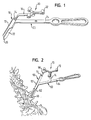
- the device according to the invention shown in FIG. 1 has an inner part 10 and an outer part 20 on.
- the guide engagement section 12 of the inner part 10 wherein the guide portion 22 is a kind of rail for the Guide engagement section 12 forms the lower part of the triangular guide engagement section 12 engages in the manner of a longitudinal guide.
- a continuous longitudinal bore or Implementation 14 through the instruments such as milling cutters or threading devices and for example, implants can also be inserted into a bone structure.
- a reference device 30 is on the inner part 10 or on the guide engagement section 12 attached, which consists of an arrangement of three reflectors 32, the position of one Navigation system can be captured.
- the reflectors 32 of the navigation star 30 have an arrangement which is characteristic of the inner part 10 and thus permits its position tracking anytime.
- the guide engagement portion 12 of the inner part 10 becomes in the guide portion 22 of the outer part 20 guided like a rail.
- the outer part 20 has on the front End of the guide section 22 on a setting tip 26, with which the outer part exactly the predetermined attachment point can be attached to the bone structure. in principle can such a setting tip on the inner part, d. H. provided at the forefront his.
- a holding section 24 which the surgeon at Can optimally use the device.
- the device shown in FIG. 2 differs from that from FIG. 1 in that that the reference device, that is, the reference star 70 not on the inner part 50, but on the Outer part 60, namely attached to the holding section 64 there. This is done using the Fastening rod 74, the reference star 70 with its reflectors at its upper end 72 wears. Otherwise, the outer part 60 of the device according to FIG. 2 again has one Holding section 64, a guide section 62 and a setting tip 66, during the Inner part 50 in turn has a guide engagement section 52 with a passage 54, that is includes a through hole 54. In this case, it is on the guide engagement portion 52 subsequent extension provided only as a handle 56 with which the inner part 50 can be handled.
- Figure 2 shows how the device according to the invention can be attached to a vertebra according to the second embodiment.
- a short skin incision is made in the middle over the vertebrae to be treated only a few centimeters long, which means it can be much shorter than conventional ones "open operations".
- the cut is deepened to the muscle packs and afterwards the skin that surrounds the muscle packs is opened.
- the pedicle, i.e. H. the area in the screw to be inserted is felt and the device according to the invention with outer part and inner part is inserted between the muscle packs until the setting tip is exactly where the screws are to enter.
- the Navigation system controls the intrusion position and corrects it if necessary, and the Entry tract is planned. Because the retractor according to the invention via the reference device can be navigated, for example, the trajectory from different angles calculated in the navigation system and displayed on a screen, and the The position of the retractor is corrected by aligning the outer part until a suitable penetration angle is ensured.
- a pedicle checker can be used to check whether there is a perforation of the pedicle towards the inner wall, which is appropriate Navigation should never occur.
- the inner part of the device according to the invention can be removed and the screw can be inserted along the guide section of the outer part into the prepared thread become.
- This process can work for multiple screws on overlying vertebrae that are not must necessarily be adjacent to each other, repeated until a sufficient number of screws are used, which are then connected with rods.
- some of the same work steps can be done directly on different vertebrae be carried out one after the other, followed by a second work step group.
- liquid implants bone craft
- a cannula is used as a guide.
Landscapes
- Health & Medical Sciences (AREA)
- Surgery (AREA)
- Orthopedic Medicine & Surgery (AREA)
- Life Sciences & Earth Sciences (AREA)
- Medical Informatics (AREA)
- Molecular Biology (AREA)
- Oral & Maxillofacial Surgery (AREA)
- Engineering & Computer Science (AREA)
- Biomedical Technology (AREA)
- Heart & Thoracic Surgery (AREA)
- Dentistry (AREA)
- Nuclear Medicine, Radiotherapy & Molecular Imaging (AREA)
- Animal Behavior & Ethology (AREA)
- General Health & Medical Sciences (AREA)
- Public Health (AREA)
- Veterinary Medicine (AREA)
- Surgical Instruments (AREA)
- Prostheses (AREA)
- Medicinal Preparation (AREA)
- Acyclic And Carbocyclic Compounds In Medicinal Compositions (AREA)
Abstract
Description
- Figur 1
- eine erfindungsgemäße Vorrichtung (Retraktor) mit einer Referenzeinrichtung am Innenteil; und
- Figur 2
- eine erfindungsgemäße Vorrichtung (Retraktor) mit einer Referenzeinrichtung am Außenteil.
Claims (12)
- Vorrichtung zur Unterstützung des Setzens von Implantaten bzw. Implantationshilfsmitteln an bzw. in einer Knochenstruktur, insbesondere an einem Wirbel, miteinem Außenteil (20, 60), das einen Halteabschnitt (24, 64) und einen Führungsabschnitt (22, 62) aufweist, undeinem Innenteil (10, 50), das einen Führungseingriffsabschnitt (12, 52) und eine Durchführung (14, 54) für ein Implantat bzw. ein Implantationshilfsmittel aufweist,wobeieine Referenzeinrichtung (30, 70) zur Navigation der Vorrichtung mittels eines medizinischen Navigationssystems am Außenteil (20, 60) und/oder am Innenteil (10, 30) angeordnet ist, wodurch das Setzen des Implantats bzw. des Implantationshilfsmittels navigationsgestützt erfolgen kann.
- Vorrichtung nach Anspruch 1, dadurch gekennzeichnet, dass die Referenzeinrichtung (30) am Innenteil (10) angeordnet ist.
- Vorrichtung nach Anspruch 1, dadurch gekennzeichnet, dass die Referenzeinrichtung (70) am Außenteil (60) angeordnet ist.
- Vorrichtung nach Anspruch 1, dadurch gekennzeichnet, dass am Innenteil (10, 50) und am Außenteil (20, 60) eine Referenzeinrichtung (30, 70) angeordnet ist.
- Vorrichtung nach einem der Ansprüche 1 bis 4, dadurch gekennzeichnet, dass sie mehrere Innenteile (10, 50) umfasst, die unterschiedlich große Durchführungen für Implantate bzw. Implantationshilfsmittel mit unterschiedlichen Abmessungen aufweisen.
- Vorrichtung nach einem der Ansprüche 1 bis 5, dadurch gekennzeichnet, dass am Innenteil und/ oder am Außenteil eine Setzspitze (26, 66) vorgesehen ist, deren Form so angepasst ist, dass sie in definierter Lage in eine passende Kalibrierungsaufnahme eines Kalibrierungsinstruments eingesetzt werden kann.
- Vorrichtung nach einem der Ansprüche 1 bis 6, dadurch gekennzeichnet, dass an dem Innenteil ein Griffabschnitt (16, 56) angeordnet ist.
- Vorrichtung nach einem der Ansprüche 1 bis 7, dadurch gekennzeichnet, dass das Innenteil (10, 50) und/oder das Außenteil aus Metall, insbesondere Stahl hergestellt sind.
- Vorrichtung nach Anspruch 8, dadurch gekennzeichnet, dass die Referenzeinrichtung eine mit einem optisch basierten Navigationssystem verfolgbare Referenzeinrichtung, insbesondere eine Reflektoren- oder Emitteranordnung ist.
- Vorrichtung nach einem der Ansprüche 1 bis 7, dadurch gekennzeichnet, dass das Innenteil (10, 50) und/oder das Außenteil aus Kunststoff, insbesondere aus Kevlar hergestellt sind.
- Vorrichtung nach Anspruch 10, dadurch gekennzeichnet, dass die Referenzeinrichtung eine mit einem magnetisch basierten Navigationssystem verfolgbare Referenzeinrichtung, insbesondere eine Miniaturspulenanordnung ist.
- Vorrichtung nach Anspruch 10 oder 11, dadurch gekennzeichnet, dass das Innenteil (10, 50) und/oder das Außenteil aus einem für Röntgenstrahlung durchlässigen Material hergestellt sind.
Priority Applications (5)
| Application Number | Priority Date | Filing Date | Title |
|---|---|---|---|
| AT02006574T ATE294536T1 (de) | 2002-03-21 | 2002-03-21 | Retraktornavigation |
| EP02006574A EP1348383B1 (de) | 2002-03-21 | 2002-03-21 | Retraktornavigation |
| DE50202992T DE50202992D1 (de) | 2002-03-21 | 2002-03-21 | Retraktornavigation |
| ES02006574T ES2241915T3 (es) | 2002-03-21 | 2002-03-21 | Dispositivo de navegacion para un retractor. |
| US10/395,019 US20030220689A1 (en) | 2002-03-21 | 2003-03-21 | Device and method for assisting in positioning implants |
Applications Claiming Priority (1)
| Application Number | Priority Date | Filing Date | Title |
|---|---|---|---|
| EP02006574A EP1348383B1 (de) | 2002-03-21 | 2002-03-21 | Retraktornavigation |
Publications (2)
| Publication Number | Publication Date |
|---|---|
| EP1348383A1 true EP1348383A1 (de) | 2003-10-01 |
| EP1348383B1 EP1348383B1 (de) | 2005-05-04 |
Family
ID=27798795
Family Applications (1)
| Application Number | Title | Priority Date | Filing Date |
|---|---|---|---|
| EP02006574A Expired - Lifetime EP1348383B1 (de) | 2002-03-21 | 2002-03-21 | Retraktornavigation |
Country Status (5)
| Country | Link |
|---|---|
| US (1) | US20030220689A1 (de) |
| EP (1) | EP1348383B1 (de) |
| AT (1) | ATE294536T1 (de) |
| DE (1) | DE50202992D1 (de) |
| ES (1) | ES2241915T3 (de) |
Cited By (2)
| Publication number | Priority date | Publication date | Assignee | Title |
|---|---|---|---|---|
| WO2008077927A3 (en) * | 2006-12-26 | 2009-05-28 | Solvay Advanced Polymers Llc | Orthopedic tool made of a plastic material |
| EP1811912A4 (de) * | 2004-11-18 | 2009-06-17 | Depuy Spine Inc | Werkzeug zur herstellung eines halswirbels und implantationsführungssysteme |
Families Citing this family (34)
| Publication number | Priority date | Publication date | Assignee | Title |
|---|---|---|---|---|
| US6159179A (en) | 1999-03-12 | 2000-12-12 | Simonson; Robert E. | Cannula and sizing and insertion method |
| JP2004516040A (ja) | 2000-06-30 | 2004-06-03 | リトラン、スティーブン | 多軸継手装置及び方法 |
| US6692434B2 (en) | 2000-09-29 | 2004-02-17 | Stephen Ritland | Method and device for retractor for microsurgical intermuscular lumbar arthrodesis |
| US7166073B2 (en) | 2000-09-29 | 2007-01-23 | Stephen Ritland | Method and device for microsurgical intermuscular spinal surgery |
| US6929606B2 (en) | 2001-01-29 | 2005-08-16 | Depuy Spine, Inc. | Retractor and method for spinal pedicle screw placement |
| WO2002060330A1 (en) | 2001-01-29 | 2002-08-08 | Stephen Ritland | Retractor and method for spinal pedicle screw placement |
| US6991632B2 (en) | 2001-09-28 | 2006-01-31 | Stephen Ritland | Adjustable rod and connector device and method of use |
| AU2002327801B2 (en) | 2001-09-28 | 2008-03-06 | Stephen Ritland | Connection rod for screw or hook polyaxial system and method of use |
| US7008431B2 (en) | 2001-10-30 | 2006-03-07 | Depuy Spine, Inc. | Configured and sized cannula |
| US7824410B2 (en) * | 2001-10-30 | 2010-11-02 | Depuy Spine, Inc. | Instruments and methods for minimally invasive spine surgery |
| US7763047B2 (en) | 2002-02-20 | 2010-07-27 | Stephen Ritland | Pedicle screw connector apparatus and method |
| US20090182341A1 (en) * | 2002-03-12 | 2009-07-16 | Cervitech, Inc. | Instrument set for fitting an intervertebral jont prosthesis |
| DE50213818D1 (de) * | 2002-03-12 | 2009-10-15 | Cervitech Inc | Intrumentarium zum Einsetzen einer Zwischenwirbelprothese |
| US7527629B2 (en) * | 2002-03-12 | 2009-05-05 | Cervitech, Inc. | Instrument set for fitting an intervertebral joint prosthesis |
| US6966910B2 (en) | 2002-04-05 | 2005-11-22 | Stephen Ritland | Dynamic fixation device and method of use |
| EP2457528A1 (de) | 2002-05-08 | 2012-05-30 | Stephen Ritland | Dynamische Befestigungsvorrichtung und Verwendungsverfahren dafür |
| US20070282347A9 (en) * | 2002-12-20 | 2007-12-06 | Grimm James E | Navigated orthopaedic guide and method |
| US8262571B2 (en) | 2003-05-22 | 2012-09-11 | Stephen Ritland | Intermuscular guide for retractor insertion and method of use |
| US7108698B2 (en) * | 2004-01-13 | 2006-09-19 | Zimmer Spine, Inc. | Combined distractor and retractor instrument and methods |
| US20050182317A1 (en) * | 2004-01-29 | 2005-08-18 | Haddad Souheil F. | Method and apparatus for locating medical devices in tissue |
| US7993341B2 (en) | 2004-03-08 | 2011-08-09 | Zimmer Technology, Inc. | Navigated orthopaedic guide and method |
| US8114086B2 (en) | 2004-03-08 | 2012-02-14 | Zimmer Technology, Inc. | Navigated cut guide locator |
| US20050203539A1 (en) * | 2004-03-08 | 2005-09-15 | Grimm James E. | Navigated stemmed orthopaedic implant inserter |
| US7909843B2 (en) | 2004-06-30 | 2011-03-22 | Thompson Surgical Instruments, Inc. | Elongateable surgical port and dilator |
| US7455639B2 (en) | 2004-09-20 | 2008-11-25 | Stephen Ritland | Opposing parallel bladed retractor and method of use |
| WO2007012025A2 (en) | 2005-07-19 | 2007-01-25 | Stephen Ritland | Rod extension for extending fusion construct |
| US7959564B2 (en) | 2006-07-08 | 2011-06-14 | Stephen Ritland | Pedicle seeker and retractor, and methods of use |
| US20080161824A1 (en) * | 2006-12-27 | 2008-07-03 | Howmedica Osteonics Corp. | System and method for performing femoral sizing through navigation |
| WO2009082656A1 (en) * | 2007-12-21 | 2009-07-02 | Smith & Nephew, Inc. | Cannula |
| WO2010078436A2 (en) * | 2008-12-30 | 2010-07-08 | Brandon Mark L | Minimally invasive endoscopic systems for placing intramedullary nails and methods therefor |
| US8828059B2 (en) | 2011-04-25 | 2014-09-09 | Warsaw Orthopedic, Inc. | Elongated connecting elements for minimally invasive surgical procedures |
| US20160120529A1 (en) * | 2014-10-31 | 2016-05-05 | Warsaw Orthopedic, Inc. | Surgical instrument and method |
| US20240307129A1 (en) * | 2021-08-04 | 2024-09-19 | University Of Florida Research Foundation, Incorporated | Neurosurgical navigation system reference array apparatus |
| USD1121826S1 (en) | 2023-08-18 | 2026-04-07 | Stryker European Operations Limited | Surgical tracker |
Citations (4)
| Publication number | Priority date | Publication date | Assignee | Title |
|---|---|---|---|---|
| DE19713416A1 (de) * | 1996-04-01 | 1997-10-30 | Asahi Optical Co Ltd | Führungsvorrichtung für ein Zwischenwirbelimplantat |
| WO1999029253A1 (en) * | 1997-12-12 | 1999-06-17 | Surgical Navigation Technologies, Inc. | Image guided spinal surgery guide, system, and method for use thereof |
| DE10005880A1 (de) * | 2000-02-10 | 2001-08-30 | Thomas Grieshammer | Vorrichtung zum Einbringen von Schrauben in einen Wirbel |
| US6351659B1 (en) * | 1995-09-28 | 2002-02-26 | Brainlab Med. Computersysteme Gmbh | Neuro-navigation system |
Family Cites Families (10)
| Publication number | Priority date | Publication date | Assignee | Title |
|---|---|---|---|---|
| US3868565A (en) * | 1973-07-30 | 1975-02-25 | Jack Kuipers | Object tracking and orientation determination means, system and process |
| US4305394A (en) * | 1980-12-22 | 1981-12-15 | Bertuch Jr Charles J | Acetabular cup positioning instrument |
| US5766221A (en) * | 1991-12-03 | 1998-06-16 | Boston Scientific Technology, Inc. | Bone anchor implantation device |
| US5320625A (en) * | 1993-01-21 | 1994-06-14 | Bertin Kim C | Apparatus and method for implanting a prosthetic acetabular cup and then testing the stability of the implant |
| US5662657A (en) * | 1996-01-17 | 1997-09-02 | Sunmed, Inc. | Intramedullary bone plug |
| US5921992A (en) * | 1997-04-11 | 1999-07-13 | Radionics, Inc. | Method and system for frameless tool calibration |
| US6235038B1 (en) * | 1999-10-28 | 2001-05-22 | Medtronic Surgical Navigation Technologies | System for translation of electromagnetic and optical localization systems |
| US6497134B1 (en) * | 2000-03-15 | 2002-12-24 | Image Guided Technologies, Inc. | Calibration of an instrument |
| US6929606B2 (en) * | 2001-01-29 | 2005-08-16 | Depuy Spine, Inc. | Retractor and method for spinal pedicle screw placement |
| EP1372516B1 (de) * | 2001-02-27 | 2009-05-13 | Smith & Nephew, Inc. | Chirurgisches navigationssystem zur teilweisen kniegelenkrekonstruktion |
-
2002
- 2002-03-21 DE DE50202992T patent/DE50202992D1/de not_active Expired - Lifetime
- 2002-03-21 ES ES02006574T patent/ES2241915T3/es not_active Expired - Lifetime
- 2002-03-21 EP EP02006574A patent/EP1348383B1/de not_active Expired - Lifetime
- 2002-03-21 AT AT02006574T patent/ATE294536T1/de not_active IP Right Cessation
-
2003
- 2003-03-21 US US10/395,019 patent/US20030220689A1/en not_active Abandoned
Patent Citations (4)
| Publication number | Priority date | Publication date | Assignee | Title |
|---|---|---|---|---|
| US6351659B1 (en) * | 1995-09-28 | 2002-02-26 | Brainlab Med. Computersysteme Gmbh | Neuro-navigation system |
| DE19713416A1 (de) * | 1996-04-01 | 1997-10-30 | Asahi Optical Co Ltd | Führungsvorrichtung für ein Zwischenwirbelimplantat |
| WO1999029253A1 (en) * | 1997-12-12 | 1999-06-17 | Surgical Navigation Technologies, Inc. | Image guided spinal surgery guide, system, and method for use thereof |
| DE10005880A1 (de) * | 2000-02-10 | 2001-08-30 | Thomas Grieshammer | Vorrichtung zum Einbringen von Schrauben in einen Wirbel |
Cited By (5)
| Publication number | Priority date | Publication date | Assignee | Title |
|---|---|---|---|---|
| EP1811912A4 (de) * | 2004-11-18 | 2009-06-17 | Depuy Spine Inc | Werkzeug zur herstellung eines halswirbels und implantationsführungssysteme |
| US7621916B2 (en) | 2004-11-18 | 2009-11-24 | Depuy Spine, Inc. | Cervical bone preparation tool and implant guide systems |
| US8298236B2 (en) | 2004-11-18 | 2012-10-30 | Depuy Spine, Inc. | Cervical bone preparation tool and implant guide systems |
| WO2008077927A3 (en) * | 2006-12-26 | 2009-05-28 | Solvay Advanced Polymers Llc | Orthopedic tool made of a plastic material |
| US9968367B2 (en) | 2006-12-26 | 2018-05-15 | Solvay Specialty Polymers Usa, L.L.C. | Orthopedic tool made of a plastic material |
Also Published As
| Publication number | Publication date |
|---|---|
| ATE294536T1 (de) | 2005-05-15 |
| DE50202992D1 (de) | 2005-06-09 |
| US20030220689A1 (en) | 2003-11-27 |
| EP1348383B1 (de) | 2005-05-04 |
| ES2241915T3 (es) | 2005-11-01 |
Similar Documents
| Publication | Publication Date | Title |
|---|---|---|
| EP1348383B1 (de) | Retraktornavigation | |
| EP1932483B1 (de) | Medizinische Einrichtung zur Lagebestimmung von intrakorporalen Implantaten | |
| EP3954312B3 (de) | Chirurgisches instrumtent | |
| EP1617792B1 (de) | Vorrichtung zur temporären schienung von zehen | |
| EP2096982B1 (de) | Vorrichtung und verfahren zum minimal-invasiven eingriff an der wirbelsäule | |
| EP2750617B1 (de) | Anatomisch angepasste, plantare knochenplatte sowie knochenplattensystem | |
| DE102007036943B4 (de) | Fußchirurgie-Knochenplatte | |
| DE4491034C2 (de) | Verschmelzungsstabilisierkammer | |
| DE69919857T2 (de) | Wirbelkörper-Distraktor | |
| DE68924114T2 (de) | Führungsinstrument zum Durchbohren der Knochenrinde, geeignet zum Auffinden der Löcher von Marknägeln. | |
| EP2214572B1 (de) | Knochennagel für die ferse | |
| EP1721583A2 (de) | Implantat zum Einsetzen zwischen Wirbelkörper sowie Operationsinstrument zum Betätigen des Implantats | |
| EP3641670B1 (de) | Instrumenten-set für wirbelsäulenoperationen | |
| DE10301444A1 (de) | Intramedullärer Nagel, Einrichtung zum Einführen einer Schraube in diesen, und zugehöriges Verfahren | |
| DE102008023760A1 (de) | Anordnung zur Bestimmung der Position und Lage eines an einem Objekt befindlichen Merkmals | |
| EP2106765B1 (de) | Bildliche Orientierungshilfe für medizinische Instrumente | |
| DE1260077B (de) | Instrument zur Durchfuehrung von Nagelungen bei Knochenbruechen | |
| EP1656071B1 (de) | Gebogenes positionier- und einführwerkzeug für das anbringen eines führungsdrahtes in den femur | |
| EP1675520A1 (de) | Vorrichtung zur platzierung von instrumenten oder implantaten in körperorgane | |
| DE102011007512B4 (de) | Vorrichtung zum Setzen eines Bohrlochs für Verriegelungselemente eines Marknagels | |
| WO2005004728A1 (de) | Zielvorrichtung | |
| DE10003051C2 (de) | Instrumentarium für die Lendenwirbelsäulenchirurgie | |
| DE202021105388U1 (de) | Endoskopisches Instrumentarium für die Bandscheibenchirurgie | |
| DE102018006442A1 (de) | Instrumenten-Set | |
| EP3095398B1 (de) | Patientenspezifisches instrument zur referenzierung von körperteilen |
Legal Events
| Date | Code | Title | Description |
|---|---|---|---|
| PUAI | Public reference made under article 153(3) epc to a published international application that has entered the european phase |
Free format text: ORIGINAL CODE: 0009012 |
|
| 17P | Request for examination filed |
Effective date: 20020321 |
|
| AK | Designated contracting states |
Kind code of ref document: A1 Designated state(s): AT BE CH CY DE DK ES FI FR GB GR IE IT LI LU MC NL PT SE TR |
|
| AX | Request for extension of the european patent |
Extension state: AL LT LV MK RO SI |
|
| AKX | Designation fees paid |
Designated state(s): AT BE CH CY DE DK ES FI FR GB GR IE IT LI LU MC NL PT SE TR |
|
| GRAP | Despatch of communication of intention to grant a patent |
Free format text: ORIGINAL CODE: EPIDOSNIGR1 |
|
| GRAS | Grant fee paid |
Free format text: ORIGINAL CODE: EPIDOSNIGR3 |
|
| GRAA | (expected) grant |
Free format text: ORIGINAL CODE: 0009210 |
|
| AK | Designated contracting states |
Kind code of ref document: B1 Designated state(s): AT BE CH CY DE DK ES FI FR GB GR IE IT LI LU MC NL PT SE TR |
|
| PG25 | Lapsed in a contracting state [announced via postgrant information from national office to epo] |
Ref country code: IE Free format text: LAPSE BECAUSE OF FAILURE TO SUBMIT A TRANSLATION OF THE DESCRIPTION OR TO PAY THE FEE WITHIN THE PRESCRIBED TIME-LIMIT Effective date: 20050504 Ref country code: NL Free format text: LAPSE BECAUSE OF FAILURE TO SUBMIT A TRANSLATION OF THE DESCRIPTION OR TO PAY THE FEE WITHIN THE PRESCRIBED TIME-LIMIT Effective date: 20050504 Ref country code: FI Free format text: LAPSE BECAUSE OF FAILURE TO SUBMIT A TRANSLATION OF THE DESCRIPTION OR TO PAY THE FEE WITHIN THE PRESCRIBED TIME-LIMIT Effective date: 20050504 |
|
| REG | Reference to a national code |
Ref country code: GB Ref legal event code: FG4D Free format text: NOT ENGLISH |
|
| REG | Reference to a national code |
Ref country code: CH Ref legal event code: EP |
|
| GBT | Gb: translation of ep patent filed (gb section 77(6)(a)/1977) |
Effective date: 20050504 |
|
| REG | Reference to a national code |
Ref country code: IE Ref legal event code: FG4D Free format text: LANGUAGE OF EP DOCUMENT: GERMAN |
|
| REF | Corresponds to: |
Ref document number: 50202992 Country of ref document: DE Date of ref document: 20050609 Kind code of ref document: P |
|
| PG25 | Lapsed in a contracting state [announced via postgrant information from national office to epo] |
Ref country code: GR Free format text: LAPSE BECAUSE OF FAILURE TO SUBMIT A TRANSLATION OF THE DESCRIPTION OR TO PAY THE FEE WITHIN THE PRESCRIBED TIME-LIMIT Effective date: 20050804 Ref country code: DK Free format text: LAPSE BECAUSE OF FAILURE TO SUBMIT A TRANSLATION OF THE DESCRIPTION OR TO PAY THE FEE WITHIN THE PRESCRIBED TIME-LIMIT Effective date: 20050804 Ref country code: SE Free format text: LAPSE BECAUSE OF FAILURE TO SUBMIT A TRANSLATION OF THE DESCRIPTION OR TO PAY THE FEE WITHIN THE PRESCRIBED TIME-LIMIT Effective date: 20050804 |
|
| PG25 | Lapsed in a contracting state [announced via postgrant information from national office to epo] |
Ref country code: PT Free format text: LAPSE BECAUSE OF FAILURE TO SUBMIT A TRANSLATION OF THE DESCRIPTION OR TO PAY THE FEE WITHIN THE PRESCRIBED TIME-LIMIT Effective date: 20051017 |
|
| NLV1 | Nl: lapsed or annulled due to failure to fulfill the requirements of art. 29p and 29m of the patents act | ||
| REG | Reference to a national code |
Ref country code: ES Ref legal event code: FG2A Ref document number: 2241915 Country of ref document: ES Kind code of ref document: T3 |
|
| REG | Reference to a national code |
Ref country code: IE Ref legal event code: FD4D |
|
| PLBE | No opposition filed within time limit |
Free format text: ORIGINAL CODE: 0009261 |
|
| STAA | Information on the status of an ep patent application or granted ep patent |
Free format text: STATUS: NO OPPOSITION FILED WITHIN TIME LIMIT |
|
| ET | Fr: translation filed | ||
| PG25 | Lapsed in a contracting state [announced via postgrant information from national office to epo] |
Ref country code: CH Free format text: LAPSE BECAUSE OF NON-PAYMENT OF DUE FEES Effective date: 20060331 Ref country code: LU Free format text: LAPSE BECAUSE OF NON-PAYMENT OF DUE FEES Effective date: 20060331 Ref country code: MC Free format text: LAPSE BECAUSE OF NON-PAYMENT OF DUE FEES Effective date: 20060331 Ref country code: LI Free format text: LAPSE BECAUSE OF NON-PAYMENT OF DUE FEES Effective date: 20060331 |
|
| PGFP | Annual fee paid to national office [announced via postgrant information from national office to epo] |
Ref country code: IT Payment date: 20060331 Year of fee payment: 5 |
|
| 26N | No opposition filed |
Effective date: 20060207 |
|
| REG | Reference to a national code |
Ref country code: CH Ref legal event code: PL |
|
| PGFP | Annual fee paid to national office [announced via postgrant information from national office to epo] |
Ref country code: AT Payment date: 20070313 Year of fee payment: 6 |
|
| PGFP | Annual fee paid to national office [announced via postgrant information from national office to epo] |
Ref country code: BE Payment date: 20070419 Year of fee payment: 6 |
|
| PGFP | Annual fee paid to national office [announced via postgrant information from national office to epo] |
Ref country code: ES Payment date: 20080328 Year of fee payment: 7 |
|
| PG25 | Lapsed in a contracting state [announced via postgrant information from national office to epo] |
Ref country code: TR Free format text: LAPSE BECAUSE OF FAILURE TO SUBMIT A TRANSLATION OF THE DESCRIPTION OR TO PAY THE FEE WITHIN THE PRESCRIBED TIME-LIMIT Effective date: 20050504 |
|
| BERE | Be: lapsed |
Owner name: *RITLAND STEPHEN Effective date: 20080331 Owner name: *BRAINLAB A.G. Effective date: 20080331 |
|
| PG25 | Lapsed in a contracting state [announced via postgrant information from national office to epo] |
Ref country code: CY Free format text: LAPSE BECAUSE OF FAILURE TO SUBMIT A TRANSLATION OF THE DESCRIPTION OR TO PAY THE FEE WITHIN THE PRESCRIBED TIME-LIMIT Effective date: 20050504 Ref country code: AT Free format text: LAPSE BECAUSE OF NON-PAYMENT OF DUE FEES Effective date: 20080321 |
|
| PG25 | Lapsed in a contracting state [announced via postgrant information from national office to epo] |
Ref country code: BE Free format text: LAPSE BECAUSE OF NON-PAYMENT OF DUE FEES Effective date: 20080331 |
|
| PG25 | Lapsed in a contracting state [announced via postgrant information from national office to epo] |
Ref country code: IT Free format text: LAPSE BECAUSE OF NON-PAYMENT OF DUE FEES Effective date: 20070321 |
|
| REG | Reference to a national code |
Ref country code: ES Ref legal event code: FD2A Effective date: 20090323 |
|
| PG25 | Lapsed in a contracting state [announced via postgrant information from national office to epo] |
Ref country code: ES Free format text: LAPSE BECAUSE OF NON-PAYMENT OF DUE FEES Effective date: 20090323 |
|
| REG | Reference to a national code |
Ref country code: FR Ref legal event code: CD Owner name: BRAINLAB AG Effective date: 20131122 Ref country code: FR Ref legal event code: CA Effective date: 20131122 |
|
| REG | Reference to a national code |
Ref country code: DE Ref legal event code: R082 Ref document number: 50202992 Country of ref document: DE Representative=s name: SCHWABE SANDMAIR MARX, DE |
|
| REG | Reference to a national code |
Ref country code: DE Ref legal event code: R082 Ref document number: 50202992 Country of ref document: DE Representative=s name: SCHWABE SANDMAIR MARX, DE Effective date: 20140113 Ref country code: DE Ref legal event code: R081 Ref document number: 50202992 Country of ref document: DE Owner name: BRAINLAB AG, DE Free format text: FORMER OWNER: BRAINLAB AG,STEPHEN RITLAND, , US Effective date: 20140113 Ref country code: DE Ref legal event code: R081 Ref document number: 50202992 Country of ref document: DE Owner name: RITLAND, STEPHEN, US Free format text: FORMER OWNER: BRAINLAB AG,STEPHEN RITLAND, , US Effective date: 20140113 Ref country code: DE Ref legal event code: R081 Ref document number: 50202992 Country of ref document: DE Owner name: RITLAND, STEPHEN, FLAGSTAFF, US Free format text: FORMER OWNER: BRAINLAB AG,STEPHEN RITLAND, , US Effective date: 20140113 Ref country code: DE Ref legal event code: R081 Ref document number: 50202992 Country of ref document: DE Owner name: BRAINLAB AG, DE Free format text: FORMER OWNERS: BRAINLAB AG, 85622 FELDKIRCHEN, DE; RITLAND, STEPHEN, FLAGSTAFF, ARIZ., US Effective date: 20140113 Ref country code: DE Ref legal event code: R081 Ref document number: 50202992 Country of ref document: DE Owner name: RITLAND, STEPHEN, FLAGSTAFF, US Free format text: FORMER OWNERS: BRAINLAB AG, 85622 FELDKIRCHEN, DE; RITLAND, STEPHEN, FLAGSTAFF, ARIZ., US Effective date: 20140113 Ref country code: DE Ref legal event code: R082 Ref document number: 50202992 Country of ref document: DE Representative=s name: SCHWABE SANDMAIR MARX PATENTANWAELTE RECHTSANW, DE Effective date: 20140113 |
|
| REG | Reference to a national code |
Ref country code: FR Ref legal event code: PLFP Year of fee payment: 15 |
|
| REG | Reference to a national code |
Ref country code: DE Ref legal event code: R082 Ref document number: 50202992 Country of ref document: DE Representative=s name: SSM SANDMAIR PATENTANWAELTE RECHTSANWALT PARTN, DE Ref country code: DE Ref legal event code: R082 Ref document number: 50202992 Country of ref document: DE Representative=s name: SCHWABE SANDMAIR MARX PATENTANWAELTE RECHTSANW, DE Ref country code: DE Ref legal event code: R081 Ref document number: 50202992 Country of ref document: DE Owner name: BRAINLAB AG, DE Free format text: FORMER OWNERS: BRAINLAB AG, 85622 FELDKIRCHEN, DE; RITLAND, STEPHEN, FLAGSTAFF, ARIZ., US Ref country code: DE Ref legal event code: R081 Ref document number: 50202992 Country of ref document: DE Owner name: RITLAND, STEPHEN, FLAGSTAFF, US Free format text: FORMER OWNERS: BRAINLAB AG, 85622 FELDKIRCHEN, DE; RITLAND, STEPHEN, FLAGSTAFF, ARIZ., US |
|
| REG | Reference to a national code |
Ref country code: FR Ref legal event code: PLFP Year of fee payment: 16 |
|
| REG | Reference to a national code |
Ref country code: FR Ref legal event code: CA Effective date: 20170706 |
|
| REG | Reference to a national code |
Ref country code: FR Ref legal event code: PLFP Year of fee payment: 17 |
|
| PGFP | Annual fee paid to national office [announced via postgrant information from national office to epo] |
Ref country code: FR Payment date: 20210323 Year of fee payment: 20 |
|
| PGFP | Annual fee paid to national office [announced via postgrant information from national office to epo] |
Ref country code: GB Payment date: 20210324 Year of fee payment: 20 Ref country code: DE Payment date: 20210319 Year of fee payment: 20 |
|
| REG | Reference to a national code |
Ref country code: DE Ref legal event code: R071 Ref document number: 50202992 Country of ref document: DE |
|
| REG | Reference to a national code |
Ref country code: GB Ref legal event code: PE20 Expiry date: 20220320 |
|
| PG25 | Lapsed in a contracting state [announced via postgrant information from national office to epo] |
Ref country code: GB Free format text: LAPSE BECAUSE OF EXPIRATION OF PROTECTION Effective date: 20220320 |