EP1348523B1 - Vorrichtung zum Anfasen von Filz - Google Patents
Vorrichtung zum Anfasen von Filz Download PDFInfo
- Publication number
- EP1348523B1 EP1348523B1 EP03251943A EP03251943A EP1348523B1 EP 1348523 B1 EP1348523 B1 EP 1348523B1 EP 03251943 A EP03251943 A EP 03251943A EP 03251943 A EP03251943 A EP 03251943A EP 1348523 B1 EP1348523 B1 EP 1348523B1
- Authority
- EP
- European Patent Office
- Prior art keywords
- edge
- felt
- cutting
- felt material
- cutting device
- Prior art date
- Legal status (The legal status is an assumption and is not a legal conclusion. Google has not performed a legal analysis and makes no representation as to the accuracy of the status listed.)
- Expired - Lifetime
Links
- 239000000463 material Substances 0.000 title claims abstract description 32
- 238000005520 cutting process Methods 0.000 claims abstract description 134
- 238000007710 freezing Methods 0.000 claims abstract description 18
- 230000008014 freezing Effects 0.000 claims abstract description 18
- 239000002699 waste material Substances 0.000 claims description 31
- 238000001035 drying Methods 0.000 claims description 8
- 238000000034 method Methods 0.000 abstract description 30
- XLYOFNOQVPJJNP-UHFFFAOYSA-N water Substances O XLYOFNOQVPJJNP-UHFFFAOYSA-N 0.000 abstract description 14
- 230000008569 process Effects 0.000 description 24
- 238000001816 cooling Methods 0.000 description 17
- 239000007789 gas Substances 0.000 description 8
- IJGRMHOSHXDMSA-UHFFFAOYSA-N Atomic nitrogen Chemical compound N#N IJGRMHOSHXDMSA-UHFFFAOYSA-N 0.000 description 7
- 239000000112 cooling gas Substances 0.000 description 5
- 238000010409 ironing Methods 0.000 description 4
- 239000002184 metal Substances 0.000 description 4
- 238000002791 soaking Methods 0.000 description 4
- 229910052757 nitrogen Inorganic materials 0.000 description 3
- 238000004804 winding Methods 0.000 description 3
- 229920000742 Cotton Polymers 0.000 description 2
- 229910000831 Steel Inorganic materials 0.000 description 2
- 239000000835 fiber Substances 0.000 description 2
- 238000003825 pressing Methods 0.000 description 2
- 239000010959 steel Substances 0.000 description 2
- 238000007796 conventional method Methods 0.000 description 1
- 239000000498 cooling water Substances 0.000 description 1
- 238000009792 diffusion process Methods 0.000 description 1
- 229910001873 dinitrogen Inorganic materials 0.000 description 1
- 239000013013 elastic material Substances 0.000 description 1
- 230000036541 health Effects 0.000 description 1
- 239000000203 mixture Substances 0.000 description 1
- 238000012986 modification Methods 0.000 description 1
- 230000004048 modification Effects 0.000 description 1
- 230000004044 response Effects 0.000 description 1
- 238000005096 rolling process Methods 0.000 description 1
Images





Classifications
-
- B—PERFORMING OPERATIONS; TRANSPORTING
- B26—HAND CUTTING TOOLS; CUTTING; SEVERING
- B26D—CUTTING; DETAILS COMMON TO MACHINES FOR PERFORATING, PUNCHING, CUTTING-OUT, STAMPING-OUT OR SEVERING
- B26D7/00—Details of apparatus for cutting, cutting-out, stamping-out, punching, perforating, or severing by means other than cutting
- B26D7/08—Means for treating work or cutting member to facilitate cutting
- B26D7/10—Means for treating work or cutting member to facilitate cutting by heating
-
- B—PERFORMING OPERATIONS; TRANSPORTING
- B26—HAND CUTTING TOOLS; CUTTING; SEVERING
- B26D—CUTTING; DETAILS COMMON TO MACHINES FOR PERFORATING, PUNCHING, CUTTING-OUT, STAMPING-OUT OR SEVERING
- B26D3/00—Cutting work characterised by the nature of the cut made; Apparatus therefor
- B26D3/02—Bevelling
Definitions
- This invention relates to a method of, and a device for, cutting the edge of felt material such as that called "Punch Carpet" at an accurately chamfered or slanted angle. For example, to make the thickness of the overlapped ends of a felt cover the same as the cover when wound around a drum of a flat sheet ironing machine.
- a drum covered with resilient pads is wound by a felt cover, and it presses the passing objects such as sheets.
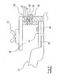
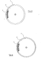
- the drum D is wound twice around its trunk by felt F which is as thick as 7 ⁇ 8mm, and the outermost end of the felt is cut around the end of its buried inner part, and by roughly overlapping both ends the felt is fixed.
- a device for chamfering an edge of felt material comprising : a worktable to receive and support the edge of the felt material; a running guide provided along the edge of the felt material on the worktable; and a uniting or mounting device which supports a cutting device for running along the edge of the felt material at a given angle to cut the edge of the felt material with an even chamfer, and which slides freely on the worktable led by the running guide; a fixing device for adhering and fixing the felt material by means of suction to a working face of the worktable; and means for jetting a freezing gas at a soaked edge of the felt material, wherein the felt fixing device includes a sensor to detect the freezing of the felt material.
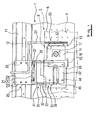
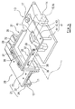
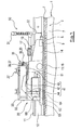
- the felt cutting device consists of a Cutting worktable 1 to position the edge of felt F, running guide 11 fixed on the cutting table 1 along the edge, a uniting (or mounting) device 20 which is slidably mounted on the cutting table 1 led by the running guide 11 at any give angle against the face of a felt edge, and cooling device 50 which is fixed to the front of cutting device 13 and makes the wet felt edge cool and harden by jetting cooling gas at the felt.
- Running guide 11 comprises three Guide rails 12, which are firmly fixed at the upper, left and right sides.
- Uniting device 20 comprising a Base body 21, which is mounted on guide rail 12 at any given angle, Slide base 26, which is united to the Base 21 adjustable to upper and lower directions, and the base 31, which firmly supports and unites cutting device 13 through angle adjusting device 35 to slide base 26.
- the base 31 to support cutting device 13 comprises of a pair of fixing plates 32, which is a set at the upper part of slide base 26 and facing each other at the front and the rear of the cutting device 13, a pair of movable plates 33 united by angle adjusting device 35 so that they can move freely to the right and left along the face of fixing plates 32, and uniting device 41, which unite cutter 13 to movable plate 33.
- the angle-adjusting device 35 is fixed, on the outer face of movable plate 33, by a guiding pin 37 that is slidable in a curved channel 36 on the inner wall of the fixed plate 32, and is fixed with fixing screw 39 inserted from outside of fixing plate 32 to movable plate 33 through arcuate opening 38.
- Connection device 41 consists of a support plate 42 which rests on the front and rear part of movable plate 33, fixing plate 43 fixed to the mounting part around the centre of the cutting device 13 and united to supporting plate 42, and to uniting post 44 which is united to the support plate 42.
- the felt fixing device 5 which can firmly affix felt F on the worktable by sucking air strongly at the suction device 8 through suction holes 6 open on the working face of the cutting table 1 can be furnished, and this felt fixing device 5 can be operated in response to a sensing device 9 which senses the freezing of Felt F.
- waste collecting bag 62 that collects the waste felt F cut off by cutter 13, and waste collecting device 60 that has a drying device 64 which dries the waste.
- the edge of felt is wetted by chilled water, hardened by a jet of cool air, and cut by cutter 13 with a given precise slanting angle, then the thickness of the overlapped edges becomes almost uniform with the rest of the parts, which makes the covered drum almost rightly cylindrical as a whole.
- the base 21 of the uniting device 20 that is united to three faces of guide-rail 12 of running-guide 11 on the cutting table 1 makes the cutting device 13 slide smoothly on the edge, even if only one side of the heavy cutting device 13 is supported by uniting device 20. And by setting felt F on the cutting table 1, it make the work smooth on long felt F too, with the running of Uniting device 20 and Cutting device 13.
- Angle-adjusting device 35 of device 20 adjusts the slanting angle of cutting device 13 through connection device 41, by sliding "Sliding Board 33" or screwing it at a right angle as well as adjusting the height, and thus form a neatly slanted face by cutting off the edge of felt at a given angle. At this time, as the edge of felt is frozen by jetting cool air, cutting by cutting device 13 is made easy and the fiber of un-knitted felt F doesn't fray or split finely.
- Connection device 41 of device 20 connects the cutting device 13, which has difference in level on its face, to movable plate 33 through Supporting plate 42, enabling the adjustment of the slanting angle of Movable plate 33 itself against Fixed plate 32 and unites cutting device 13 to cooperative set device 20 and support firmly.
- Felt Fixing Device 5 draws the felt F firmly to the worktable to prevent it from moving during a cutting operation.
- Waste Collecting Device 60 prevents powdered fiber-waste, cotton waste and others from flying, and by drying the frozen waste it enables them to be reused.
- Reference numeral 1 signifies Cutting Work Table.
- the length of this table 1 is equivalent to that of the felt cover to be mounted, for example, around the periphery of Drum D of a flat sheet ironing machine, and a little wider than the width necessary to have Cutting Device 13 run and set Felt F as later described, and has a stipulated height of table-top.
- Felt fixing device 5 that sucks and fixes a felt F that is mounted on the tabletop mentioned above.
- Felt fixing device 5 comprises a Suction Hopper 7 which has a plurality of Suction Holes 6 all over its face from under the working face and is connected to Suction device 8 such as a Vacuum Pump through an appropriate suction pipe.
- Suction device 8 is controlled by Sensing device 9 in the form of a thermal sensor to detect the freezing temperature when felt F has been frozen by the later stated cooling device 50. And it is designed to stop when cutting process comes to an end, as felt hardening device 5 functions following Suction device 8 turns on when the freezing process of felt F starts.
- Cutting worktable 1 is of steel with a give section, and on top of its working table is fixed a running guide I 1 on which runs Cutting device 13 along the edge of the felt F to be cut with a given slant.
- This running guide 11 is made of steel and is of inverted channel shape.
- On the top, right and left walls of it are firmly fixed guide rails 12, and by being united by uniting (or mounting) device 20 later explained Cutting device 13 is mounted in a slidable manner and cooling device 50 is also attached.
- Cutting device 13 which is guided by Guide rails 12 has a cutting body 14 mainly of rectangular cast metal which is placed with its own weight and Running device 15 which is united to cutting body 14 so that it will run on the working face of Cutting work table 1 and cutter 16 which appears and disappears freely at an arranged protruding distance from the bottom of Cutting body 14.
- This cutter 16 is arranged symmetrically for example 180° or in the quite the opposite place in the Running device 15 (i.e. running roller which is driven rotating itself) which is set in an exposable manner at the bottom of cutting device 14, and it cuts the edge of felt F to a given depth running along the felt edge by the rotation of this running roller.
- the exposure of the blade is adjustable taking how deep it cuts the felt into account.
- openings i.e. suction port 61 of Waste collecting device 60 which is to be described later.
- This cutting device 13 is united to Running guide 11 by Uniting device 20 which is mounted by Guide rail 12 in a slidable manner.
- This Uniting device 20 includes angle-adjusting device 35 which adjusts the angle of inclination of Cutter 16 in Cutting device 13, namely the angle of entire Cutting device 13.
- This Uniting device 20 comprises a Base 21, which is mounted on the Guide Rail 12 in a slidable manner, Slide base 26 which is united to Base 21 in a manner that is slideable upward and downward, and fixing base body 31 to support Cutting device 13 and unites it to Base 21 through Angle Adjusting Device 35.
- Base 21 is arranged at the side of Upper base 22 which is at the top of Running Guide 11 and Cutting device 13 of running guide 11, and is formed of inverted channel shape with side sliding base 23 which has the height as tall as the upper part of Upper Base 22 and Side base 24 which is at the opposite side of Running Guide 11 where there is no Cutting device 13.
- Side base 23 which has the height as tall as the upper part of Upper Base 22 and Side base 24 which is at the opposite side of Running Guide 11 where there is no Cutting device 13.
- Cam follower 25 arranged in movable and spinable manner at the upper face and right and left sides of running guide 11. This Cam Follower 25 surround Running Guide 11 biting each Guide Rail 12, and along Running Guide 11 Cutting Device 13 is led smoothly.
- Slide Base 26 is able to slide up and down by screwing and unscrewing the up-down adjusting screw 27 which is put on to the side of Side Slide base 23.
- This up-down adjusting screw 27 has a butterfly-like shape as shown in the Drawing, but it can have a handle (not shown).
- Supporting Base 31 has various shapes to suit the outer shape of Cutting Device 13 as shown in Figure 4. As the drawing shows it has a pair of Fixing plates 32 at the front and rear of Cutting Device 13 on the Slide Base 26, a pair of Movable plates 33 at the front and rear coordinated by Angle Adjustment Device 35 which enables it to move right and left along this Fixing plate 32, and Uniting Device 41 to unite Cutting Device 13 to Movable plate 33.
- Fixing plate 32 and Movable plate 33 are rectangular plates which lie along right and left of Cutting device 13, and can be fixed firmly along fixing plate 32.
- Angle Adjusting board 35 fixes Guiding Pin 37 in arcuate Guide channel 36 in Fixing plate 32 to the outside of Movable plate 33.
- the pin 37 is, at the same time, inserted into the arcuate fixing hole 38.
- Fixing screw 39 is screwed into Movable plate 33 from the outside of Fixing plate 32.
- Movable plate 33 can be moved along Guide slot 36 against Fixing plate 32.
- fixing screw 39 the angle of moveable position can be maintained.
- Uniting device 41 consists of Support plate 42 on the front and rear pair of Movable plate 33, Fixing plate 43 which is fixed to the protruding part in the center of Cutting Device 13 and united to Support plate 42, and Uniting Post 44 which rests on the rear top of Cutting device 13 and is united to Support plate 42.
- Sign 45 in the drawing shows an evading hole to avoid Operating Handle 14 prepared on top of Cutting device 13.
- the make-up of the Uniting Device 41 is designed to make Movable plate 33 fit the uneven top of Cutting device 13, therefore, depending upon the shape of Cutting device 13, its make-up is not limited to the example of this drawing.
- Cooling & Hardening device 50 is located at the front of Cutting device 13 as shown in Figures 1, 3, 7, 8, and jet out freezing gas such as liquefied nitrogen to freeze the cold water emitted on the edge of felt F to be cut slantingly.
- this Cooling device 50 has a supply pipe 51 which is united to a gas cylinder containing cooling gas (not shown) and plural Jetting pipes 52 which diverge from supply pipe 51 and have jetting outlets on the edge of felt F. And it is designed to run along with the movement of Cutting Device 13 by fixing supply pipe 51 on Base body 21 of uniting device 20.
- Cooling & Hardening device 50 is also designed to jet out cold water for cooling using replacing switch (not shown), hence extra outlet to jet out cooling water becomes unnecessary.
- Cooling & Hardening Device 50 runs backward with Cutting device 13 and Coordinated set 20 on the cutting work table 1 jetting out water on the edge of felt F, then as the second step, waiting for cold water to percolate sufficiently across the edge of felt, replacing the switch, jetting out freezing gas, driving Device 50 forward with Cutting device 13 and uniting device 20, you can cut frozen edge at a given angle by Cutting device 13.
- Supply pipe 51 is turned toward the front of Cutting device 13 on Base 21, and along the front edge of Cutting device 13 it is bent upward and then bent along the front edge.
- Plural Jetting pipe 52 diverges along this front edge.
- Jetting pipe 52 is formed bendable with plural hollow structures as shown in the drawings, and its Jetting port is made horizontally long so that it lies along the front edge of Cutting device 13.
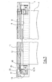
- FIG 9 another embodiment is shown. It has Waste collecting device 60 which collects the waste made by cutting felt F with Cutting device 13.
- This Waste collecting device 60 has Waste collecting bag 62 which collects the waste made by cutting felt F with Cutting device 13, and Drying device 63 which dries the waste.
- Waste collecting bag 62 which is connected to Suction port 61 opened at the rear of Cutter 16 of cutting device 13 and at the end of the bag is a Suction device 63 in the form of a vacuum pump coordinated, and beneath waste collecting bag 62 is Drying device 64.
- This waste-collecting device 60 is not necessarily mounted on Cutting device 13. Although the drawing is abbreviated, some appropriate waste collecting pipe can be connected to Suction port 61 (the pipe should be made flexible), then for example, you can lead it to Waste collecting device 62, Suction device 63, and Drying device 64 placed on somewhere appropriate of the edge of Cutting table 1.
- Cutter 16 of Cutting device 13 is to be adjusted to have its proper width of blade pushed out from the bottom, and then Cutting device 13 is to be tilted by the operation of Angle adjusting device 35 of uniting device 20; 10 degrees or so.
- Angle adjusting device 35 of uniting device 20 10 degrees or so.
- Cooling & Hardening process S2 by Cooling and hardening device 50 can be done prior to the process of Tilting angle setting process S3, when gas jetting from Cooling & Hardening device 50 stationed at the front of Cutting device 13 is done against the edge of felt by the running of Cooperating set device 20 and Cutting device 13.
- Cutting device 13 is to run along Running guide 11 with tilted Cutter 16 along the edge of felt F.
- RUNNIG PROCESS ---STEP 4: S4 This way, by letting Tilted Cutter 16 run along the edge of felt F, Cutter 16 of Cutting device 13 cuts off the cooled and hardened edge of felt F into an inclined plane with a given inclination.
- Cutting process -STEP5: S5 When cutting work of the surface of one side is finished, the felt F is to be turned over, and the edge of the other end is to be cut off with inclination. And then, as shown in Figure 11, finished felt F is to be wound on a resilient support made of springs, which covers the whole surface of Drum D of the ironing machine, by overlapping both edges of the opposite side of slantingly processed ends.
- the edges of felt F with inclination in cutting the edges of felt F with inclination, the edges can be cut easily just as in cutting metal precisely as the edges are frozen before cutting. Therefore the thickness or the height of the processed section overlapped with each other is almost the same as the rest of felt F on Drum D of Sheet-roll machine; hence the cross section of Drum D is almost circular. This enables Drum D to produce uniform pressure on all the surface of sheet.
- This invention produces felt to cover Drum D with the same thickness whose edges are cut off with given inclination.
- the surface of processed felt F is smooth without unevenness.
- this invention has such processes as S 1 to wet the edge of felt F with cold water, S2 freezing process to freeze the edge, S3 the adjustment of Cutter 16 and the adjustment of angle of Cutter 13, S4 running process of Cutting device 13 on the edge, and S5 to cut the edges with inclination, it can cut unwoven felt F easily with precise inclination just like cutting metal.
- Waste collecting device 60 As cooling gas to freeze the edge of water-infiltrated felt F is nitrogen, its jet freezes the edge instantly. And the gas is safe if it is diffused into the air, and free from harmful influence upon human health and the things around. (However, of course, a local exhauster is to be equipped.)
- Waste collecting device 60 the waste fiber caused through cutting work is collected into Waste collecting bag 62, which prevents the diffusion of waste and contribute to keep the working environment clean.
- the cut waste is dried by drying device 64 for its reuse, so it is not wasted.
- this invention has Cutting work table 1 which holds the edge of felt F and is equipped with Running guide 11 along the edge, Cutter 16 at its bottom, uniting device 20 which sets Cutting device 13 at a given angle of inclination in running along the edge of felt F, and enables Cutting device 13 to slide freely on Cutting work table 1, and Cooling device 50 which is arranged at the front of Cutting device 13 and freezes the edge by jetting out freezing gas against the edge of long moistened felt. So it can finish the process of freezing the wet edge of felt F, the process of each S1, S2, S3, S4, or S5 like running on the edge and cutting the edge by inclined Cutting device 13 quickly.
- this invention is equipped with guiding rail 12 on the top and on both sides of running guide 11 of cutting work table, and on this guide rail 12 base body 21 of uniting device 20 has been equipped by biting each other. So heavy Cutting device 13 made of cast metal can run without vibration along running guide 11 on the edge of felt if supported only one side by Supporting base body 31 of uniting device 20, and it can make the edge of felt F into a neat section with given inclination free from fine splits or unevenness.
- Base body 21 which is held by guide rail 12 by biting each other slide free
- Supporting device 31 through Slide base 26 and Angle adjusting device 35
- it can set the height of Cutting device 13 by sliding it upward or downward in accordance with the thickness of the edge and the angle of inclination of Cutting device 13 and Cutter 16 easily.
- Supporting base body 31 of uniting device 20 has Fixing board 32 which are a set of plates placed front and rear facing each other on top of Slide base 26, Moveable plate 33 which is cooperated by moveable angle adjusting device 35 along this Fixing plate 32, and Uniting device 41 which makes Cutting device 13 united to Moveable plate 33.
- Angle adjusting device 35 fixes Guiding pin 37 which is put in the arc-shaped guiding gutter 36 in the inner wall of Fixing plate 32 slide free on the outside of Moveable plate 33.
- Angle adjusting device 35 makes fixing screw 39 screwed into moveable board 33 from the outside of Fixing board 32 by piercing into Adjusting & fixing hole 38 opened in Fixing board 32, so it can freely adjust the angle of Cutting device 13 supported by Uniting device 41 by deciding and fixing the position of Moving plate 33 with Fixing screw 39 as well as with the adjustment of Moveable plate 33 on the fixing plate 32.
- Uniting device 41 consists of supporting board 42 which is bridged over a set of moveable plate 33, fixing plate 43 which is united to supporting board 42, and uniting post 44 which is united to supporting plate 42, it can have co-supportive structure with cutting device 13 which has variety of shapes, and at the same time can have a wide use.
- this invention can fix felt F on the worktable 1 by adsorbing it onto the surface of the table.
- Felt F is firmly fixed in being cut by cutting device 13 that runs on cutting table 1. Therefore when the edge of felt is cut with inclination, the section can be precise, which makes the thickness of the overlapped part of the felt the same as the rest of the felt wound around drum D. Hence the cross section of the drum D around which processed felt is wound can be truly circular.
Landscapes
- Life Sciences & Earth Sciences (AREA)
- Forests & Forestry (AREA)
- Engineering & Computer Science (AREA)
- Mechanical Engineering (AREA)
- Physics & Mathematics (AREA)
- Optics & Photonics (AREA)
- Treatment Of Fiber Materials (AREA)
- Perforating, Stamping-Out Or Severing By Means Other Than Cutting (AREA)
- Nonmetal Cutting Devices (AREA)
- Details Of Cutting Devices (AREA)
Claims (7)
- Vorrichtung zum Anfasen eines Rands von Filzmaterial, wobei die Vorrichtung Folgendes umfasst:a) einen Arbeitstisch (1) zum Aufnehmen und Tragen des Rands des Filzmaterials;a) eine Laufführung (11), die entlang dem Rand des Filzmaterials auf dem Arbeitstisch (1) bereitgestellt ist; undb) eine Zusammenfügungs- oder Befestigungsvorrichtung (20), die eine Schneidvorrichtung (13) trägt zum Entlanglaufen am Rand des Filzmaterials in einem bestimmten Winkel, um den Rand des Filzmaterials mit einer gleichmäßigen Fase zu schneiden, und die von der Laufführung (11) geführt frei auf dem Arbeitstisch (1) gleitet;c) eine Fixiervorrichtung (5) zum Anbringen und Fixieren des Filzmaterials mithilfe von Saugkraft auf einer Arbeitsfläche des Arbeitstisches undd) ein Mittel (50) zum Hervorstoßen eines gefrierenden Gases auf einen eingeweichten Rand des Filzmaterials, dadurch gekennzeichnet, dass die Filzfixiervorrichtung einen Sensor (9) hat zum Erkennen des Gefrierens des Filzmaterials.
- Vorrichtung nach Anspruch 1, bei der die Laufführung (11) an der oberen, der linken und der rechten Seite Führungsschienen (12) hat.
- Vorrichtung nach Anspruch 1 oder Anspruch 2, bei der die Zusammenfügungs- oder Befestigungsvorrichtung (20) einen Basiskörper (21), der an einer Führungsschiene (12) der Laufführung (11) angebracht ist, eine Gleitbasis (26), die mit diesem Basiskörper (21) verbunden ist, und einen Basiskörper (31) zum Tragen der Schneidvorrichtung (13) mit einer Winkeleinstellvorrichtung (35) hat.
- Vorrichtung nach Anspruch 3, bei der das tragende Basisteil (31) ein Paar einander zugekehrter Fixierplatten (32) an der oberen Vorderseite und der oberen Rückseite der Schneidvorrichtung (13) auf der Gleitbasis (26), ein Paar Gleitplatten (33) vom und hinten, die durch die Winkeleinstellvorrichtung zusammengefügt sind, die sich nach links und nach rechts entlang der Stirnfläche der Fixierplatte bewegt, und eine Zusammenfügungsvorrichtung (41) zum Zusammenfügen der Schneidvorrichtung mit der Gleitplatte hat.
- Vorrichtung nach Anspruch 4, bei der die Winkeleinstellvorrichtung (35) einen in die Fixierplatte (32) gelegten verstellbaren Führungsstift (37), der in einen von der Seite betrachtet bogenförmigen Führungsschlitz zu legen ist, durch Einsetzen von Schrauben von der Außenseite der Fixierplatte entlang dem Führungsschlitz in die Einstelllöcher der in dem Bogen gepunkteten Fixierplatte (32) an der beweglichen Platte (33) fixiert.
- Vorrichtung nach Anspruch 4 oder Anspruch 5, bei der die Zusammenfügungsvorrichtung (41) an der Trägerplatte (42) zwischen der vorderen und hinteren beweglichen Platte (33) und an einem vorspringenden Teil um die Mitte der Schneidvorrichtung befestigt ist und auf Fixierplatte (43), die mit Trägerplatte (42) zusammengefügt ist, und auf der hinteren Oberseite der Schneidvorrichtung (13) aufliegt.
- Vorrichtung nach einem der Ansprüche 1 bis 6, die ferner eine Staubsammelvorrichtung (60) mit einem Beutel (62) zum Aufsammeln von unverwertbarem Filzabfall und eine Trockenvorrichtung (64) zum Trocknen von Filzabfall umfasst.
Applications Claiming Priority (2)
| Application Number | Priority Date | Filing Date | Title |
|---|---|---|---|
| JP2002090201 | 2002-03-28 | ||
| JP2002090201A JP2003285292A (ja) | 2002-03-28 | 2002-03-28 | フェルト生地材端縁部の傾斜切除方法及びその切除装置 |
Publications (3)
| Publication Number | Publication Date |
|---|---|
| EP1348523A2 EP1348523A2 (de) | 2003-10-01 |
| EP1348523A3 EP1348523A3 (de) | 2005-01-05 |
| EP1348523B1 true EP1348523B1 (de) | 2007-02-07 |
Family
ID=27800500
Family Applications (1)
| Application Number | Title | Priority Date | Filing Date |
|---|---|---|---|
| EP03251943A Expired - Lifetime EP1348523B1 (de) | 2002-03-28 | 2003-03-27 | Vorrichtung zum Anfasen von Filz |
Country Status (4)
| Country | Link |
|---|---|
| EP (1) | EP1348523B1 (de) |
| JP (1) | JP2003285292A (de) |
| AT (1) | ATE353272T1 (de) |
| DE (1) | DE60311601T2 (de) |
Families Citing this family (5)
| Publication number | Priority date | Publication date | Assignee | Title |
|---|---|---|---|---|
| CN102554964A (zh) * | 2010-12-27 | 2012-07-11 | 上海新安汽车隔音毡有限公司 | 一种隔音毡的冲切模具 |
| GB2512568A (en) * | 2013-01-28 | 2014-10-08 | Vestas Wind Sys As | A method and an apparatus for providing a tapered edge on a sheet comprising a fibrous material |
| ES2632058T3 (es) | 2012-06-25 | 2017-09-08 | Vestas Wind Systems A/S | Método y aparato para proporcionar un borde con sección decreciente sobre una lámina que comprende un material fibroso |
| CN110142816B (zh) * | 2019-06-05 | 2020-12-25 | 安徽海东环保科技有限公司 | 波纹管制造方法 |
| CN116141725B (zh) * | 2023-02-08 | 2024-11-22 | 扬州市邗江扬子汽车内饰件有限公司 | 一种轻量环保电池罩结构及加工工艺 |
Family Cites Families (5)
| Publication number | Priority date | Publication date | Assignee | Title |
|---|---|---|---|---|
| GB191502554A (en) * | 1915-02-17 | 1915-08-12 | Thomas Aubrey Evans | Improvements in or relating to Devices for Cutting Bevel Edges on Cardboard and the like. |
| US2691417A (en) * | 1949-11-09 | 1954-10-12 | Scholl Mfg Co Inc | Apparatus for beveling felt protective pads |
| DE2702472C2 (de) * | 1977-01-21 | 1984-09-06 | Kleindienst GmbH, 8900 Augsburg | Mangel mit einem auf dem Umfang einer Mangelrolle vorgesehenen Belag |
| WO1984002451A1 (fr) * | 1982-12-29 | 1984-07-05 | Reichert Karl Gmbh | Procede d'usinage et/ou de manipulation de materiau plat |
| US5317943A (en) * | 1990-03-06 | 1994-06-07 | Robert K. Dowdle | Method and apparatus for ultrasonically cutting mat board |
-
2002
- 2002-03-28 JP JP2002090201A patent/JP2003285292A/ja active Pending
-
2003
- 2003-03-27 EP EP03251943A patent/EP1348523B1/de not_active Expired - Lifetime
- 2003-03-27 AT AT03251943T patent/ATE353272T1/de not_active IP Right Cessation
- 2003-03-27 DE DE60311601T patent/DE60311601T2/de not_active Expired - Lifetime
Also Published As
| Publication number | Publication date |
|---|---|
| EP1348523A2 (de) | 2003-10-01 |
| DE60311601T2 (de) | 2007-11-22 |
| DE60311601D1 (de) | 2007-03-22 |
| ATE353272T1 (de) | 2007-02-15 |
| EP1348523A3 (de) | 2005-01-05 |
| JP2003285292A (ja) | 2003-10-07 |
Similar Documents
| Publication | Publication Date | Title |
|---|---|---|
| US3790051A (en) | Semiconductor wafer fracturing technique employing a pressure controlled roller | |
| TWI557029B (zh) | 貼標裝置 | |
| FI83177B (fi) | Foerfarande och underlag foer att understoeda och daervid bearbeta arkmaterial. | |
| GB2190869A (en) | Laser cutting system | |
| EP1348523A2 (de) | Verfahren sowie Vorrichtung zum Anfasen von Filz | |
| CN108393597A (zh) | 一种激光平切极耳装置 | |
| JP2966409B1 (ja) | シート材の切断装置 | |
| US4694719A (en) | Vacuum die cutting apparatus | |
| CN111015787A (zh) | 一种旅行箱生产用板材切割设备 | |
| JPS61279450A (ja) | ロ−ラすえ付け装置 | |
| CN114260874A (zh) | 一种汽车座椅套生产用划线装置 | |
| CN214815244U (zh) | 一种板材精准自动切割装置 | |
| JP2002264079A (ja) | シート材裁断装置 | |
| CN220311471U (zh) | 铝框门冲孔加工装置 | |
| FR2867994A1 (fr) | Amenagement d'une scie sauteuse electroportative pour decoupe de saignees dans cloisons | |
| US4364291A (en) | Frame for a reciprocable circular saw | |
| CN113997350A (zh) | 一种雨衣生产用布料裁断装置 | |
| CN218224063U (zh) | 一种辊轧机吸边结构 | |
| CN214934576U (zh) | 一种带薄膜分切装置的pu薄膜收卷机 | |
| CN217943945U (zh) | 一种降解塑料袋成型碎屑收集装置 | |
| CN211104300U (zh) | 一种pvc阻燃板生产用分切装置 | |
| CN222697341U (zh) | 一种保温装饰复合一体化板开槽加工装置 | |
| CN119458497A (zh) | 一种pe-rt地暖管加工切割设备 | |
| CN220219166U (zh) | 一种砖表面切割设备 | |
| JP4235497B2 (ja) | 縁無薄畳仕上げ装置 |
Legal Events
| Date | Code | Title | Description |
|---|---|---|---|
| PUAI | Public reference made under article 153(3) epc to a published international application that has entered the european phase |
Free format text: ORIGINAL CODE: 0009012 |
|
| AK | Designated contracting states |
Kind code of ref document: A2 Designated state(s): AT BE BG CH CY CZ DE DK EE ES FI FR GB GR HU IE IT LI LU MC NL PT RO SE SI SK TR |
|
| AX | Request for extension of the european patent |
Extension state: AL LT LV MK |
|
| 17P | Request for examination filed |
Effective date: 20040311 |
|
| PUAL | Search report despatched |
Free format text: ORIGINAL CODE: 0009013 |
|
| AK | Designated contracting states |
Kind code of ref document: A3 Designated state(s): AT BE BG CH CY CZ DE DK EE ES FI FR GB GR HU IE IT LI LU MC NL PT RO SE SI SK TR |
|
| AX | Request for extension of the european patent |
Extension state: AL LT LV MK |
|
| AKX | Designation fees paid |
Designated state(s): AT BE BG CH CY CZ DE DK EE ES FI FR GB GR HU IE IT LI LU MC NL PT RO SE SI SK TR |
|
| RTI1 | Title (correction) |
Free format text: DEVICE FOR CHAMFERING THE EDGE OF FELT MATERIAL |
|
| GRAP | Despatch of communication of intention to grant a patent |
Free format text: ORIGINAL CODE: EPIDOSNIGR1 |
|
| GRAS | Grant fee paid |
Free format text: ORIGINAL CODE: EPIDOSNIGR3 |
|
| GRAA | (expected) grant |
Free format text: ORIGINAL CODE: 0009210 |
|
| AK | Designated contracting states |
Kind code of ref document: B1 Designated state(s): AT BE BG CH CY CZ DE DK EE ES FI FR GB GR HU IE IT LI LU MC NL PT RO SE SI SK TR |
|
| PG25 | Lapsed in a contracting state [announced via postgrant information from national office to epo] |
Ref country code: BE Free format text: LAPSE BECAUSE OF FAILURE TO SUBMIT A TRANSLATION OF THE DESCRIPTION OR TO PAY THE FEE WITHIN THE PRESCRIBED TIME-LIMIT Effective date: 20070207 Ref country code: CH Free format text: LAPSE BECAUSE OF FAILURE TO SUBMIT A TRANSLATION OF THE DESCRIPTION OR TO PAY THE FEE WITHIN THE PRESCRIBED TIME-LIMIT Effective date: 20070207 Ref country code: LI Free format text: LAPSE BECAUSE OF FAILURE TO SUBMIT A TRANSLATION OF THE DESCRIPTION OR TO PAY THE FEE WITHIN THE PRESCRIBED TIME-LIMIT Effective date: 20070207 Ref country code: DK Free format text: LAPSE BECAUSE OF FAILURE TO SUBMIT A TRANSLATION OF THE DESCRIPTION OR TO PAY THE FEE WITHIN THE PRESCRIBED TIME-LIMIT Effective date: 20070207 Ref country code: AT Free format text: LAPSE BECAUSE OF FAILURE TO SUBMIT A TRANSLATION OF THE DESCRIPTION OR TO PAY THE FEE WITHIN THE PRESCRIBED TIME-LIMIT Effective date: 20070207 Ref country code: NL Free format text: LAPSE BECAUSE OF FAILURE TO SUBMIT A TRANSLATION OF THE DESCRIPTION OR TO PAY THE FEE WITHIN THE PRESCRIBED TIME-LIMIT Effective date: 20070207 Ref country code: FI Free format text: LAPSE BECAUSE OF FAILURE TO SUBMIT A TRANSLATION OF THE DESCRIPTION OR TO PAY THE FEE WITHIN THE PRESCRIBED TIME-LIMIT Effective date: 20070207 Ref country code: SI Free format text: LAPSE BECAUSE OF FAILURE TO SUBMIT A TRANSLATION OF THE DESCRIPTION OR TO PAY THE FEE WITHIN THE PRESCRIBED TIME-LIMIT Effective date: 20070207 |
|
| REG | Reference to a national code |
Ref country code: GB Ref legal event code: FG4D |
|
| REG | Reference to a national code |
Ref country code: CH Ref legal event code: EP |
|
| REG | Reference to a national code |
Ref country code: IE Ref legal event code: FG4D |
|
| REF | Corresponds to: |
Ref document number: 60311601 Country of ref document: DE Date of ref document: 20070322 Kind code of ref document: P |
|
| PG25 | Lapsed in a contracting state [announced via postgrant information from national office to epo] |
Ref country code: SE Free format text: LAPSE BECAUSE OF FAILURE TO SUBMIT A TRANSLATION OF THE DESCRIPTION OR TO PAY THE FEE WITHIN THE PRESCRIBED TIME-LIMIT Effective date: 20070507 |
|
| PG25 | Lapsed in a contracting state [announced via postgrant information from national office to epo] |
Ref country code: BG Free format text: LAPSE BECAUSE OF EXPIRATION OF PROTECTION Effective date: 20070508 |
|
| PG25 | Lapsed in a contracting state [announced via postgrant information from national office to epo] |
Ref country code: ES Free format text: LAPSE BECAUSE OF FAILURE TO SUBMIT A TRANSLATION OF THE DESCRIPTION OR TO PAY THE FEE WITHIN THE PRESCRIBED TIME-LIMIT Effective date: 20070518 |
|
| PG25 | Lapsed in a contracting state [announced via postgrant information from national office to epo] |
Ref country code: PT Free format text: LAPSE BECAUSE OF FAILURE TO SUBMIT A TRANSLATION OF THE DESCRIPTION OR TO PAY THE FEE WITHIN THE PRESCRIBED TIME-LIMIT Effective date: 20070709 |
|
| NLV1 | Nl: lapsed or annulled due to failure to fulfill the requirements of art. 29p and 29m of the patents act | ||
| ET | Fr: translation filed | ||
| REG | Reference to a national code |
Ref country code: CH Ref legal event code: PL |
|
| PG25 | Lapsed in a contracting state [announced via postgrant information from national office to epo] |
Ref country code: SK Free format text: LAPSE BECAUSE OF FAILURE TO SUBMIT A TRANSLATION OF THE DESCRIPTION OR TO PAY THE FEE WITHIN THE PRESCRIBED TIME-LIMIT Effective date: 20070207 |
|
| PLBE | No opposition filed within time limit |
Free format text: ORIGINAL CODE: 0009261 |
|
| STAA | Information on the status of an ep patent application or granted ep patent |
Free format text: STATUS: NO OPPOSITION FILED WITHIN TIME LIMIT |
|
| PG25 | Lapsed in a contracting state [announced via postgrant information from national office to epo] |
Ref country code: RO Free format text: LAPSE BECAUSE OF FAILURE TO SUBMIT A TRANSLATION OF THE DESCRIPTION OR TO PAY THE FEE WITHIN THE PRESCRIBED TIME-LIMIT Effective date: 20070207 Ref country code: CZ Free format text: LAPSE BECAUSE OF FAILURE TO SUBMIT A TRANSLATION OF THE DESCRIPTION OR TO PAY THE FEE WITHIN THE PRESCRIBED TIME-LIMIT Effective date: 20070207 |
|
| 26N | No opposition filed |
Effective date: 20071108 |
|
| PG25 | Lapsed in a contracting state [announced via postgrant information from national office to epo] |
Ref country code: MC Free format text: LAPSE BECAUSE OF NON-PAYMENT OF DUE FEES Effective date: 20070331 Ref country code: IE Free format text: LAPSE BECAUSE OF NON-PAYMENT OF DUE FEES Effective date: 20070327 |
|
| PG25 | Lapsed in a contracting state [announced via postgrant information from national office to epo] |
Ref country code: GR Free format text: LAPSE BECAUSE OF FAILURE TO SUBMIT A TRANSLATION OF THE DESCRIPTION OR TO PAY THE FEE WITHIN THE PRESCRIBED TIME-LIMIT Effective date: 20070508 |
|
| PG25 | Lapsed in a contracting state [announced via postgrant information from national office to epo] |
Ref country code: EE Free format text: LAPSE BECAUSE OF FAILURE TO SUBMIT A TRANSLATION OF THE DESCRIPTION OR TO PAY THE FEE WITHIN THE PRESCRIBED TIME-LIMIT Effective date: 20070207 |
|
| PG25 | Lapsed in a contracting state [announced via postgrant information from national office to epo] |
Ref country code: CY Free format text: LAPSE BECAUSE OF FAILURE TO SUBMIT A TRANSLATION OF THE DESCRIPTION OR TO PAY THE FEE WITHIN THE PRESCRIBED TIME-LIMIT Effective date: 20070207 |
|
| PG25 | Lapsed in a contracting state [announced via postgrant information from national office to epo] |
Ref country code: LU Free format text: LAPSE BECAUSE OF NON-PAYMENT OF DUE FEES Effective date: 20070327 |
|
| PG25 | Lapsed in a contracting state [announced via postgrant information from national office to epo] |
Ref country code: TR Free format text: LAPSE BECAUSE OF FAILURE TO SUBMIT A TRANSLATION OF THE DESCRIPTION OR TO PAY THE FEE WITHIN THE PRESCRIBED TIME-LIMIT Effective date: 20070207 Ref country code: HU Free format text: LAPSE BECAUSE OF FAILURE TO SUBMIT A TRANSLATION OF THE DESCRIPTION OR TO PAY THE FEE WITHIN THE PRESCRIBED TIME-LIMIT Effective date: 20070808 |
|
| PGFP | Annual fee paid to national office [announced via postgrant information from national office to epo] |
Ref country code: FR Payment date: 20120403 Year of fee payment: 10 |
|
| PGFP | Annual fee paid to national office [announced via postgrant information from national office to epo] |
Ref country code: DE Payment date: 20120323 Year of fee payment: 10 |
|
| PGFP | Annual fee paid to national office [announced via postgrant information from national office to epo] |
Ref country code: GB Payment date: 20120322 Year of fee payment: 10 |
|
| PGFP | Annual fee paid to national office [announced via postgrant information from national office to epo] |
Ref country code: IT Payment date: 20120328 Year of fee payment: 10 |
|
| GBPC | Gb: european patent ceased through non-payment of renewal fee |
Effective date: 20130327 |
|
| REG | Reference to a national code |
Ref country code: FR Ref legal event code: ST Effective date: 20131129 |
|
| REG | Reference to a national code |
Ref country code: DE Ref legal event code: R119 Ref document number: 60311601 Country of ref document: DE Effective date: 20131001 |
|
| PG25 | Lapsed in a contracting state [announced via postgrant information from national office to epo] |
Ref country code: GB Free format text: LAPSE BECAUSE OF NON-PAYMENT OF DUE FEES Effective date: 20130327 Ref country code: FR Free format text: LAPSE BECAUSE OF NON-PAYMENT OF DUE FEES Effective date: 20130402 Ref country code: DE Free format text: LAPSE BECAUSE OF NON-PAYMENT OF DUE FEES Effective date: 20131001 |
|
| PG25 | Lapsed in a contracting state [announced via postgrant information from national office to epo] |
Ref country code: IT Free format text: LAPSE BECAUSE OF NON-PAYMENT OF DUE FEES Effective date: 20130327 |