EP1348527A2 - Procédé pour fabriquer un composant céramique et un dispositif de moulage - Google Patents
Procédé pour fabriquer un composant céramique et un dispositif de moulage Download PDFInfo
- Publication number
- EP1348527A2 EP1348527A2 EP03006535A EP03006535A EP1348527A2 EP 1348527 A2 EP1348527 A2 EP 1348527A2 EP 03006535 A EP03006535 A EP 03006535A EP 03006535 A EP03006535 A EP 03006535A EP 1348527 A2 EP1348527 A2 EP 1348527A2
- Authority
- EP
- European Patent Office
- Prior art keywords
- tool
- powder
- pressing
- filling
- ceramic
- Prior art date
- Legal status (The legal status is an assumption and is not a legal conclusion. Google has not performed a legal analysis and makes no representation as to the accuracy of the status listed.)
- Withdrawn
Links
Images




Classifications
-
- B—PERFORMING OPERATIONS; TRANSPORTING
- B30—PRESSES
- B30B—PRESSES IN GENERAL
- B30B11/00—Presses specially adapted for forming shaped articles from material in particulate or plastic state, e.g. briquetting presses, tabletting presses
- B30B11/02—Presses specially adapted for forming shaped articles from material in particulate or plastic state, e.g. briquetting presses, tabletting presses using a ram exerting pressure on the material in a moulding space
- B30B11/04—Presses specially adapted for forming shaped articles from material in particulate or plastic state, e.g. briquetting presses, tabletting presses using a ram exerting pressure on the material in a moulding space co-operating with a fixed mould
- B30B11/06—Presses specially adapted for forming shaped articles from material in particulate or plastic state, e.g. briquetting presses, tabletting presses using a ram exerting pressure on the material in a moulding space co-operating with a fixed mould each charge of the material being compressed against the previously formed body
-
- B—PERFORMING OPERATIONS; TRANSPORTING
- B28—WORKING CEMENT, CLAY, OR STONE
- B28B—SHAPING CLAY OR OTHER CERAMIC COMPOSITIONS; SHAPING SLAG; SHAPING MIXTURES CONTAINING CEMENTITIOUS MATERIAL, e.g. PLASTER
- B28B13/00—Feeding the unshaped material to moulds or apparatus for producing shaped articles; Discharging shaped articles from such moulds or apparatus
- B28B13/02—Feeding the unshaped material to moulds or apparatus for producing shaped articles
- B28B13/0215—Feeding the moulding material in measured quantities from a container or silo
- B28B13/022—Feeding several successive layers, optionally of different materials
-
- B—PERFORMING OPERATIONS; TRANSPORTING
- B28—WORKING CEMENT, CLAY, OR STONE
- B28B—SHAPING CLAY OR OTHER CERAMIC COMPOSITIONS; SHAPING SLAG; SHAPING MIXTURES CONTAINING CEMENTITIOUS MATERIAL, e.g. PLASTER
- B28B13/00—Feeding the unshaped material to moulds or apparatus for producing shaped articles; Discharging shaped articles from such moulds or apparatus
- B28B13/02—Feeding the unshaped material to moulds or apparatus for producing shaped articles
- B28B13/0215—Feeding the moulding material in measured quantities from a container or silo
- B28B13/023—Feeding the moulding material in measured quantities from a container or silo by using a feed box transferring the moulding material from a hopper to the moulding cavities
-
- B—PERFORMING OPERATIONS; TRANSPORTING
- B30—PRESSES
- B30B—PRESSES IN GENERAL
- B30B15/00—Details of, or accessories for, presses; Auxiliary measures in connection with pressing
- B30B15/30—Feeding material to presses
- B30B15/302—Feeding material in particulate or plastic state to moulding presses
-
- B—PERFORMING OPERATIONS; TRANSPORTING
- B30—PRESSES
- B30B—PRESSES IN GENERAL
- B30B15/00—Details of, or accessories for, presses; Auxiliary measures in connection with pressing
- B30B15/30—Feeding material to presses
- B30B15/302—Feeding material in particulate or plastic state to moulding presses
- B30B15/304—Feeding material in particulate or plastic state to moulding presses by using feed frames or shoes with relative movement with regard to the mould or moulds
- B30B15/306—Feeding material in particulate or plastic state to moulding presses by using feed frames or shoes with relative movement with regard to the mould or moulds for multi-layer articles
Definitions
- the present invention relates to a method for producing a component from at least two ceramic materials which differ in at least one property, which comprises the steps: Powder production, Pouring the powder into a molding tool, and Burn.
- ceramic represents a collective term for inorganic, non-metallic materials. While the traditional ceramic is based on silicate, advanced ceramics based on non-silicate (e.g. Al 2 O 3 ) and non-oxide (e.g. Carbide) compounds are based.
- a characteristic of ceramic materials is the manufacturing process, which consists of the process steps of powder manufacturing, shaping and firing. The raw materials are generally in a natural or artificially produced fine-grained distribution (powder) and are then subjected to a shaping process (for example injection molding or pressing process) in order to be finally compacted by firing at high temperatures and thereby solidified.
- the ferroelectric ceramic includes, for example, the piezoceramic, the capacitor ceramic, the semiconductor ceramic and the electrical and optical storage ceramic.
- Pressing processes are mostly used to shape ceramic components.
- standard procedures are, for example, wet or dry pressing.
- the raw mass is between the two stamps brought so that a so-called by moving the lower and upper stamps together Green compact is pressed, which is burned in the following process step.
- Wet and dry pressing differ mainly in the moisture content of the raw materials used a green body to be formed.
- the sequence of the two procedures cited is otherwise essentially the same.
- ceramic mass is fed into the
- the upper stamp then moves in the direction of the lower stamp and begins to compress the mass in the press tool.
- a movable lower punch there is also a pressing or compensating movement in order to To improve the quality of the green body.
- the upper and lower punches move back to their respective starting positions so that the green body, e.g. B. with the help of an ejector, can be demolded and fired.
- the present invention has for its object to provide a method that allows To produce green compacts, each made of at least two ceramic masses of different compositions exist, so that the possible uses of the fired component greatly increased are, and carried out at the same time with inexpensive to manufacture shaping tools can be.
- This object is achieved according to the invention by a method in which the powder or the ceramic Raw mass of at least two different compositions together in one Shaping tool or a chamber of a shaping tool can be filled.
- the powder or the ceramic Raw mass of at least two different compositions together in one Shaping tool or a chamber of a shaping tool can be filled.
- a pressing tool is preferably used as the shaping tool and the compression and The various masses are connected seamlessly by a pressing process.
- This variant will characterized in more detail below by further preferred measures, with corresponding ones Embodiments largely transferable to the alternative injection molding technology are.
- the method according to the invention can be used both in conventional pressing tools, which have only one chamber, as well as in pressing tools, which are already in several chambers are divided. According to the invention are then in at least one chamber of the press tool several chambers at least two ceramic raw materials with different compositions arranged side by side or one above the other.
- the filling is particularly preferably carried out in a pressing tool that consists of an upper and a lower punch consists.
- the ceramic raw materials are placed between the upper and lower punches. If the upper and lower stamps are moved towards each other, this can be between the upper and lower stamps located ceramic raw mass can be pressed or compressed so that the desired Blank is created.
- a special embodiment provides that the filling takes place in a press tool, in which at least one stamp, preferably the lower stamp, has a die frame that the Stamp essentially surrounds, the die frame and stamp movable relative to each other are.
- the die frame can be used serve as an adjustable wall of the press tool. For example, it is possible to use the die frame to move relative to the lower stamp in the direction of the upper stamp, so that the lower stamp facing the die frame from the upper punch.
- the resulting one Chamber that is open at the top, with the lower stamp the bottom of the chamber and the inside of the die frame forming the side walls of the chamber can be filled to the brim with a first ceramic Raw mass of certain composition can be filled. Possibly too much stuff Material can be stripped from the lower punch or die frame, for example, with the aid of a scraper become.
- the die frame can be moved further relative to the lower stamp in the direction of the Upper stamp are moved so that in principle another chamber is created, the.
- Bottom of Chamber is now formed from the surface of the first ceramic mass and the inside of the Matrix frames form the side walls of the chamber.
- a second ceramic mass can be used another composition can be filled into this chamber, so that in the vertical direction Different areas arise in the ceramic mass, which have a different composition exhibit.
- upper and lower punches are moved towards each other, so that the ceramic masses be pressed and a green body is formed.
- the green body then also points in the vertical direction Areas with different compositions.
- the pressing tools are filled using so-called filling slides or filling funnels.
- a particularly preferred embodiment of the method therefore sees the use of a Press tool in front, which has at least two filling slides or funnels, each for receiving ceramic raw mass of certain composition are provided.
- a filling slide or filling funnel can be used for filling a lower layer and for filling an upper layer the other filling slide or filling funnel.
- An alternative embodiment of the present invention provides that a press tool for Filling is used which has a filling slide which has at least two separate compartments, each for taking up ceramic masses or powders of different compositions are provided. With the help of such a filling slide it is easily possible to differentiate ceramic masses Arrange the composition horizontally next to each other.
- a pressing tool that has at least two filling slides has, at least one filling slide also at least two compartments for receiving powder has different compositions.
- Fig. 1 the arrangement of the parts of the pressing tool is shown schematically, which is particularly preferred is used for carrying out the method according to the invention.
- the so-called To see lower stamp 1 a square base in the embodiment shown Has. It is understood that the shape of the surface can be varied depending on the application. So can the lower stamp may also have a circular or elliptical shape, for example.
- the lower stamp is surrounded by the so-called die frame 2.
- the die frame 2 can be moved relative to the lower stamp 1.
- the lower stamp 1 relative to Matrix frame 2 moved into the paper plane, a kind of chamber is created, the bottom the same from the lower punch 1 and the walls from the inner walls of the die frame 2 be formed.
- three filling slides 3, 4, 5 can also be seen, which are approximately to the side the lower stamp 1 are arranged.
- the filling slide provided here with the reference number 3 has a partition so that two compartments 3, 3 'are created, each for receiving ceramic Serve masses or powders of different compositions.
- the three filling slides 3, 4, 5 serve the supply of four different ceramic raw materials with different compositions.
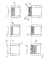
- a first embodiment of the present method can be seen in FIG.
- the top left is So-called basic position 7 of the press tool is shown.
- Die frame 2 and lower punch 1 are located itself at about the same vertical height. Is located slightly above the lower stamp 1 the upper stamp 6.
- the die frame 2 is in relation to the lower stamp 1 in Moved in the direction of the upper punch 6 until a first filling position 8 is reached.
- the first material or the first ceramic raw mass with the help of the first fill slide 3 31 introduced with a certain composition. This is in the middle picture of the top one Row clarifies.
- the die frame 2 is a little further towards the upper stamp 6 moves until the second filling position 9 is reached.
- the second material 41 is introduced into the resulting chamber (top right).
- Excess material that may protrude beyond the die frame 2 can be used, for example Be removed from the press with the aid of a scraper.
- the flowchart shown in FIG. 3 differs in that, in contrast to FIG. 2, the die frame 2 is immovably arranged here, while the lower punch 1 during the filling process away from the upper punch 6 to the filling positions 8 ', 9' and 10 '.
- the die frame 2 remains here throughout Process on the same level.
- the upper punch 6 first moves up to the height of the die frame 2, whereupon the lower punch 1 moves in the direction of the upper punch 6 and thereby compacting the ceramic raw materials.
- the flowchart shown in FIG. 4 differs from that shown in FIG. 2 only in that that the upper punch 1 even engages in the die frame 2 during the compression phase, d. H. moves up to a level in the direction of the lower stamp 1, which is below that of the Matrix frame 2 predetermined basic level.
- the compression takes place here through simultaneous Moving or pressing upper punch 6 and lower punch 1 instead.
- the manufacturing method described makes it possible to use two or more different ceramic materials to be arranged horizontally and / or vertically in the component in succession, so that in the green compact there are no parting levels or joints.
- the resulting component is in one piece and has Zones with different properties. So it is possible, for example, the electrical resistance to vary along the ceramic component, so that, for example, in a predetermined Most of the resistive heat is generated when there is one between two connections Voltage is applied.
- the described method makes it possible to apply materials with different properties any part of the component to incorporate local areas with different properties realize. It is also possible, for example, to have the component on its surface with different properties to be provided so that the surface quality is increased. Alternatively or in combination of course, electrical or mechanical parameters can also be used within the component can be varied. In addition, optical designs can be easily implemented. In that press tool and filling slide can be moved in a coordinated manner, different ceramic granules can be be distributed locally defined in the compact. The uses of ceramics are obviously expanded and the production of components from different ceramic masses significantly simplified and cheaper. The very expensive subsequent joining processes that were previously required are no longer required by the present method. In the event that zones with very different physical properties, such as. B. very different coefficients of thermal expansion, should be arranged directly next to each other, it can be advantageous if an intermediate layer is additionally provided, for example a medium thermal one Has expansion coefficients, so that the difference occurring in the thermal expansion coefficient is reduced in the transition areas.
- an intermediate layer is additionally provided, for example a medium thermal
- FIG. 5 is an illustration of the functional sequence, similar to that in FIG. 2.
- the filling slides can be placed on the die frame one after the other be, as is clearly shown in Figure 6.
- the filling slide 1 is on the die frame put on when component 1 is filled in after component 1 has been filled in, the filling slide 1 can be moved back laterally. Then the same process is repeated with the filling slide 2 and then with the filling slide 3, which has a partition in the middle has, so that two different components 3 and 4 are filled into the die frame can be.
- the upper punch is put on and pressed against the lower punch, thereby compacting the ceramic mass. Subsequently the die frame is withdrawn or the lower punch relative to the die frame pushed upwards so that the compacted green compact can be removed from the lower stamp can.
Landscapes
- Engineering & Computer Science (AREA)
- Mechanical Engineering (AREA)
- Manufacturing & Machinery (AREA)
- Chemical & Material Sciences (AREA)
- Ceramic Engineering (AREA)
- Press-Shaping Or Shaping Using Conveyers (AREA)
- Devices For Post-Treatments, Processing, Supply, Discharge, And Other Processes (AREA)
- Compositions Of Oxide Ceramics (AREA)
Applications Claiming Priority (2)
| Application Number | Priority Date | Filing Date | Title |
|---|---|---|---|
| DE10213215 | 2002-03-25 | ||
| DE10213215A DE10213215A1 (de) | 2002-03-25 | 2002-03-25 | Verfahren zur Herstellung eines keramischen Bauteils |
Publications (2)
| Publication Number | Publication Date |
|---|---|
| EP1348527A2 true EP1348527A2 (fr) | 2003-10-01 |
| EP1348527A3 EP1348527A3 (fr) | 2005-04-20 |
Family
ID=27798166
Family Applications (1)
| Application Number | Title | Priority Date | Filing Date |
|---|---|---|---|
| EP03006535A Withdrawn EP1348527A3 (fr) | 2002-03-25 | 2003-03-24 | Procédé pour fabriquer un composant céramique et un dispositif de moulage |
Country Status (2)
| Country | Link |
|---|---|
| EP (1) | EP1348527A3 (fr) |
| DE (1) | DE10213215A1 (fr) |
Cited By (3)
| Publication number | Priority date | Publication date | Assignee | Title |
|---|---|---|---|---|
| DE102014006374A1 (de) * | 2014-05-05 | 2015-11-05 | Gkn Sinter Metals Engineering Gmbh | Vorrichtung zur Herstellung eines Rohlings nebst Verfahren hierzu und Rohling |
| WO2015169740A1 (fr) | 2014-05-05 | 2015-11-12 | Gkn Sinter Metals Engineering Gmbh | Élément de stockage d'hydrogène pour réservoir de stockage d'hydrogène |
| IT202100011450A1 (it) * | 2021-05-05 | 2022-11-05 | Istituto Naz Fisica Nucleare | Metodo e apparecchiatura per la produzione di oggetti mediante stampa tridimensionale e sinterizzazione |
Families Citing this family (1)
| Publication number | Priority date | Publication date | Assignee | Title |
|---|---|---|---|---|
| DE102009042598A1 (de) * | 2009-09-23 | 2011-03-24 | Gkn Sinter Metals Holding Gmbh | Verfahren zur Herstellung eines Grünlings |
Family Cites Families (5)
| Publication number | Priority date | Publication date | Assignee | Title |
|---|---|---|---|---|
| DE525059C (de) * | 1931-05-18 | Scheidhauer & Giessing Akt Ges | Verfahren und Vorrichtung zur Herstellung eines Formlings aus mehreren Stoffschichten | |
| ATE69287T1 (de) * | 1987-01-16 | 1991-11-15 | Inax Corp | Mehrschichtige fliese und verfahren zu deren herstellung. |
| CA2106053C (fr) * | 1992-09-16 | 1998-08-04 | Yoshinori Kakamu | Carreau a motif et procede pour sa fabrication |
| ATE122278T1 (de) * | 1993-01-08 | 1995-05-15 | Mirage Ceramica Spa | Verfahren zum herstellen von trockenen fliesen, mit seiner formanlage und den hergestellten fliesen. |
| DE4331590C1 (de) * | 1993-09-17 | 1994-08-11 | Porextherm Daemmstoffe Gmbh | Verpreßtes Isolier-Verbundformteil |
-
2002
- 2002-03-25 DE DE10213215A patent/DE10213215A1/de not_active Withdrawn
-
2003
- 2003-03-24 EP EP03006535A patent/EP1348527A3/fr not_active Withdrawn
Cited By (9)
| Publication number | Priority date | Publication date | Assignee | Title |
|---|---|---|---|---|
| DE102014006374A1 (de) * | 2014-05-05 | 2015-11-05 | Gkn Sinter Metals Engineering Gmbh | Vorrichtung zur Herstellung eines Rohlings nebst Verfahren hierzu und Rohling |
| WO2015169740A1 (fr) | 2014-05-05 | 2015-11-12 | Gkn Sinter Metals Engineering Gmbh | Élément de stockage d'hydrogène pour réservoir de stockage d'hydrogène |
| WO2015169756A2 (fr) | 2014-05-05 | 2015-11-12 | Gkn Sinter Metals Engineering Gmbh | Dispositif destiné à la fabrication d'une ébauche, procédé associé et ébauche |
| JP2017520403A (ja) * | 2014-05-05 | 2017-07-27 | ゲーカーエン シンター メタルズ エンジニアリング ゲーエムベーハー | ブランク製造装置、ブランク製造方法、及びブランク |
| US10919250B2 (en) | 2014-05-05 | 2021-02-16 | Gkn Sinter Metals Engineering Gmbh | Apparatus for producing a blank, also a method for this purpose and a blank |
| EP4085993A1 (fr) | 2014-05-05 | 2022-11-09 | GKN Sinter Metals Engineering GmbH | Dispositif de fabrication d'une ébauche, ainsi que procédé et ébauche |
| EP4094826A1 (fr) | 2014-05-05 | 2022-11-30 | GKN Sinter Metals Engineering GmbH | Dispositif de fabrication d'une ébauche, ainsi que procédé et ébauche |
| US11572272B2 (en) | 2014-05-05 | 2023-02-07 | Gkn Sinter Metals Engineering Gmbh | Process for producing a hydrogen storage means |
| IT202100011450A1 (it) * | 2021-05-05 | 2022-11-05 | Istituto Naz Fisica Nucleare | Metodo e apparecchiatura per la produzione di oggetti mediante stampa tridimensionale e sinterizzazione |
Also Published As
| Publication number | Publication date |
|---|---|
| EP1348527A3 (fr) | 2005-04-20 |
| DE10213215A1 (de) | 2003-10-16 |
Similar Documents
| Publication | Publication Date | Title |
|---|---|---|
| EP2480359B1 (fr) | Procédé de fabrication d'une ébauche appareil pour sa fabrication et programme d'ordinateur | |
| DE102010054608A1 (de) | Verfahren und Vorrichtung für das Querpassagenpressen zum Herstellen von Schneideinsätzen | |
| EP0633440A1 (fr) | Procédé pour la préparation d'un support de frittage | |
| DE102011117317B4 (de) | Umformwerkzeuganordnung für Mikrobauteile | |
| DE102011117316B4 (de) | Umformwerkzeuganordnung für Mikrobauteile | |
| CH650710A5 (de) | Verfahren zur herstellung eines metallischen sinterformteils. | |
| DE3689422T2 (de) | Verfahren zum Herstellen von Steinen in einer Presse und Presse zum Herstellen gennanter Steine. | |
| EP1348527A2 (fr) | Procédé pour fabriquer un composant céramique et un dispositif de moulage | |
| DE1584803C3 (de) | Verfahren zur Herstellung von großformatigen, aus feuerfestem Material bestehenden Formkörpern mit durchgehenden Öffnungen kleinen Durchmessers | |
| AT402375B (de) | Verfahren und vorrichtung zum herstellen von hohlbausteinen | |
| WO2006056286A1 (fr) | Dispositif et procede de production horizontale de gateau de charbon compact | |
| DE102013009055B4 (de) | Werkzeug und Verfahren zur Herstellung von Salzkernen für das Druckgießen von Metallen | |
| EP1982393B1 (fr) | Procédé et un dispositif de fabrication d'une pièce moulée sous pression à plusieurs couches | |
| DE102019100590A1 (de) | Betonpflasterstein sowie Produktlage von Betonpflastersteinen sowie Verfahren zur Herstellung von Betonpflastersteinen in einer Produktlage | |
| DE2417589A1 (de) | Verfahren und anordnung zum herstellen von verdichteten legierten gegenstaenden mit einem inneren durchtritt | |
| DE2462434A1 (de) | Form zum herstellen von spritzlingen aus ungebrannter porzellanmasse | |
| DE69122339T2 (de) | Verfahren zur Herstellung eines Pulverformkörpers | |
| DE1584423C3 (de) | Verfahren und Presse zum Verdichten von mineralischer PreBmasse | |
| DE10034167A1 (de) | Form zur Herstellung von Formkörpern | |
| DE2005871A1 (de) | Form zum maschinellen Herstellen von Verbundsteinen | |
| DE703145C (de) | Verfahren und Vorrichtung zum Herstellen von Schmelzhaefen, insbesondere Glasschmelzhaefen | |
| DE3329585C2 (fr) | ||
| DE19703176C2 (de) | Verfahren zur Herstellung von keramischen oder pulvermetallurgischen Bauteilen | |
| DE2831166A1 (de) | Einrichtung zum steuern und regeln an einer kunststeinpresse | |
| EP1125703A2 (fr) | Procédé et dispositif pour la fabrication de corps moules |
Legal Events
| Date | Code | Title | Description |
|---|---|---|---|
| PUAI | Public reference made under article 153(3) epc to a published international application that has entered the european phase |
Free format text: ORIGINAL CODE: 0009012 |
|
| AK | Designated contracting states |
Kind code of ref document: A2 Designated state(s): AT BE BG CH CY CZ DE DK EE ES FI FR GB GR HU IE IT LI LU MC NL PT RO SE SI SK TR |
|
| AX | Request for extension of the european patent |
Extension state: AL LT LV MK |
|
| PUAL | Search report despatched |
Free format text: ORIGINAL CODE: 0009013 |
|
| AK | Designated contracting states |
Kind code of ref document: A3 Designated state(s): AT BE BG CH CY CZ DE DK EE ES FI FR GB GR HU IE IT LI LU MC NL PT RO SE SI SK TR |
|
| AX | Request for extension of the european patent |
Extension state: AL LT LV MK |
|
| AKX | Designation fees paid | ||
| STAA | Information on the status of an ep patent application or granted ep patent |
Free format text: STATUS: THE APPLICATION IS DEEMED TO BE WITHDRAWN |
|
| 18D | Application deemed to be withdrawn |
Effective date: 20051021 |
|
| REG | Reference to a national code |
Ref country code: DE Ref legal event code: 8566 |