EP1348533B1 - Procédé pour la fabrication d'une plaque à puits multiples - Google Patents
Procédé pour la fabrication d'une plaque à puits multiples Download PDFInfo
- Publication number
- EP1348533B1 EP1348533B1 EP02015910A EP02015910A EP1348533B1 EP 1348533 B1 EP1348533 B1 EP 1348533B1 EP 02015910 A EP02015910 A EP 02015910A EP 02015910 A EP02015910 A EP 02015910A EP 1348533 B1 EP1348533 B1 EP 1348533B1
- Authority
- EP
- European Patent Office
- Prior art keywords
- multiwell plate
- plate body
- mold cavity
- wells
- clear lens
- Prior art date
- Legal status (The legal status is an assumption and is not a legal conclusion. Google has not performed a legal analysis and makes no representation as to the accuracy of the status listed.)
- Expired - Lifetime
Links
Images



Classifications
-
- B—PERFORMING OPERATIONS; TRANSPORTING
- B29—WORKING OF PLASTICS; WORKING OF SUBSTANCES IN A PLASTIC STATE IN GENERAL
- B29D—PRODUCING PARTICULAR ARTICLES FROM PLASTICS OR FROM SUBSTANCES IN A PLASTIC STATE
- B29D11/00—Producing optical elements, e.g. lenses or prisms
-
- B—PERFORMING OPERATIONS; TRANSPORTING
- B01—PHYSICAL OR CHEMICAL PROCESSES OR APPARATUS IN GENERAL
- B01L—CHEMICAL OR PHYSICAL LABORATORY APPARATUS FOR GENERAL USE
- B01L3/00—Containers or dishes for laboratory use, e.g. laboratory glassware; Droppers
- B01L3/50—Containers for the purpose of retaining a material to be analysed, e.g. test tubes
- B01L3/508—Rigid containers without fluid transport within
- B01L3/5085—Rigid containers without fluid transport within for multiple samples, e.g. microtitration plates
-
- B—PERFORMING OPERATIONS; TRANSPORTING
- B29—WORKING OF PLASTICS; WORKING OF SUBSTANCES IN A PLASTIC STATE IN GENERAL
- B29C—SHAPING OR JOINING OF PLASTICS; SHAPING OF MATERIAL IN A PLASTIC STATE, NOT OTHERWISE PROVIDED FOR; AFTER-TREATMENT OF THE SHAPED PRODUCTS, e.g. REPAIRING
- B29C45/00—Injection moulding, i.e. forcing the required volume of moulding material through a nozzle into a closed mould; Apparatus therefor
- B29C45/16—Making multilayered or multicoloured articles
- B29C45/1635—Making multilayered or multicoloured articles using displaceable mould parts, e.g. retractable partition between adjacent mould cavities
-
- B—PERFORMING OPERATIONS; TRANSPORTING
- B29—WORKING OF PLASTICS; WORKING OF SUBSTANCES IN A PLASTIC STATE IN GENERAL
- B29C—SHAPING OR JOINING OF PLASTICS; SHAPING OF MATERIAL IN A PLASTIC STATE, NOT OTHERWISE PROVIDED FOR; AFTER-TREATMENT OF THE SHAPED PRODUCTS, e.g. REPAIRING
- B29C45/00—Injection moulding, i.e. forcing the required volume of moulding material through a nozzle into a closed mould; Apparatus therefor
- B29C45/17—Component parts, details or accessories; Auxiliary operations
- B29C45/46—Means for plasticising or homogenising the moulding material or forcing it into the mould
- B29C45/56—Means for plasticising or homogenising the moulding material or forcing it into the mould using mould parts movable during or after injection, e.g. injection-compression moulding
- B29C45/561—Injection-compression moulding
-
- B—PERFORMING OPERATIONS; TRANSPORTING
- B01—PHYSICAL OR CHEMICAL PROCESSES OR APPARATUS IN GENERAL
- B01L—CHEMICAL OR PHYSICAL LABORATORY APPARATUS FOR GENERAL USE
- B01L2200/00—Solutions for specific problems relating to chemical or physical laboratory apparatus
- B01L2200/12—Specific details about manufacturing devices
-
- B—PERFORMING OPERATIONS; TRANSPORTING
- B01—PHYSICAL OR CHEMICAL PROCESSES OR APPARATUS IN GENERAL
- B01L—CHEMICAL OR PHYSICAL LABORATORY APPARATUS FOR GENERAL USE
- B01L2300/00—Additional constructional details
- B01L2300/08—Geometry, shape and general structure
- B01L2300/0848—Specific forms of parts of containers
- B01L2300/0851—Bottom walls
-
- B—PERFORMING OPERATIONS; TRANSPORTING
- B29—WORKING OF PLASTICS; WORKING OF SUBSTANCES IN A PLASTIC STATE IN GENERAL
- B29C—SHAPING OR JOINING OF PLASTICS; SHAPING OF MATERIAL IN A PLASTIC STATE, NOT OTHERWISE PROVIDED FOR; AFTER-TREATMENT OF THE SHAPED PRODUCTS, e.g. REPAIRING
- B29C45/00—Injection moulding, i.e. forcing the required volume of moulding material through a nozzle into a closed mould; Apparatus therefor
- B29C45/14—Injection moulding, i.e. forcing the required volume of moulding material through a nozzle into a closed mould; Apparatus therefor incorporating preformed parts or layers, e.g. injection moulding around inserts or for coating articles
- B29C45/14336—Coating a portion of the article, e.g. the edge of the article
Definitions
- This invention relates to techniques for forming multiwell plates and, more particularly, to molding multiwell plates.
- Multiwell plates are known in the prior art for use in bioassays. It is also known from the prior art to have a clear lens at the base of the wells to allow researchers to use optically-based analytical techniques for studying materials within the wells, such as tissue cultures.
- multiwell plates having a clear lens Various techniques have been developed to form multiwell plates having a clear lens.
- the body of the multiwell plate (which is typically made of opaque material to minimize reflectance) is separately formed from the clear lens, with the clear lens being bonded to the body.
- both components are injection molded.
- a multiwell plate body is initially injection molded, but not ejected from the mold. Thereafter, a thin film is placed in the mold with a clear layer of clear plastic being molded over the film to form the lens portion.
- a method corresponding to the first part of claim 1 is disclosed in EP 0 844 025 A2.
- a micro plate which has discrete, separate sample wells.
- the micro plate comprises a plurality of opaque cylindrical tubes. Each tube contains a transparent well.
- the tubes shrouding the side walls of the wells extend beyond the ends of the wells, each well being thermally bonded to the matrix formed by the tubes, so as to form an integral structure.
- the method of the present invention is defined by claim 1 .
- the subject invention provides a method which utilizes injection-compression for forming a multiwell plate having a clear lens.
- a multiwell plate body is initially injection molded and left in a mold cavity. Thereafter, the mold cavity is adjusted to define a second mold cavity adjacent to an end of the multiwell plate body.
- a clear lens portion is formed in the second mold cavity using injection-compression, which also causes the lens to be fused to the multiwell plate body.
- injection-compression a bolus of molten material is injected into the second mold cavity.
- the second mold cavity is adjusted such that its volume is reduced, resulting in compression of the molten material.
- the combined effect of the reduction of volume of the second mold cavity, and the compressive forces acting on the molten material results in a complete filling of the reduced-volume second mold cavity and formation of a clear lens which is fused to the multiwell plate body.
- the multiwell plate can be formed of different materials: for example, a colored polymer for the multiwell plate body, and a clear polymer from the same polymer family for the clear lens.
- a colored polymer for the multiwell plate body and a clear polymer from the same polymer family for the clear lens.
- the same material, but of different colors can be used, such as a colored polystyrene to form the multiwell plate body, and a clear polystyrene to form the lens. In selecting materials, proper adhesion of the clear lens and the multiwell plate body must be considered.
- the technique allows for a clear lens to be more consistently formed than in the prior art, resulting in less loss of light in optical recording and improved imaging. Also, lower levels of molded-in stress in the clear lens are found than with prior art techniques resulting in better optical properties. Furthermore, the physical properties (e.g., flexural modulus) of the clear lens may be improved and higher material densification may be achieved with injection-compression.
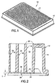
- FIG. 1 is a perspective view of a multiwell plate
- FIG. 2 is a partial cross-sectional elevational view of a multiwell plate
- FIG. 3 is a schematic representing formation of a multiwell plate body in a first mold cavity
- FIG. 4 is a schematic representing adjustment of the mold elements to define a second mold cavity
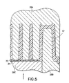
- FIG. 5 is a schematic showing a bolus of molten material disposed in the second mold cavity.
- FIG. 6 is a schematic representing the multiwell plate in the mold cavities.
- a typical multiwell plate 10 is shown therein having a multiwell plate body 12 with an array of wells 14 formed therethrough.
- the use of multiwell plates in bioassays is well known in the prior art, and the multiwell plate 10 is formed to be compatible, both structurally and dimensionally, with such bioassay techniques.
- certain arrays of the wells 14 have been accepted in the prior art, including an array of 96 wells, 384 wells (as shown in FIG. 1), and 1,536 wells. Beyond the conventional numbers of wells, any number may be used in any array configuration.
- the multiwell plate body 12 is preferably unitarily formed of a thermoplastic material, and includes a sidewall 16 and a network of inner walls 18 which define the wells 14 .
- the walls 18 are preferably tapered so as to diverge from upper ends 20 of the walls 18 to lower ends 22 of the walls. As a result, the wells 14 are each downwardly convergent.
- a clear lens 24 is fixed to the lower portions 22 of the walls 18 so as to at least partially cover the wells 14 and to seal the bottoms thereof.
- the lens 24 covers and seals all of the wells 14 so that no intermixing between the wells 14 may occur.
- the clear lens 24 is generally planar, having flat opposing surfaces 26 which are generally parallel. As shown in FIG. 2, it is preferred that all portions of the clear lens 24 be below the walls 18 , with no portion extending into any of the wells 14 .
- the thickness T of the clear lens 24 be in the range of 0,10 mm (.004 inches) - 0,38 mm (.015 inches). With this relatively low range of thicknesses, and with good planarity of the clear lens 24 , highly-acceptable optical characteristics with the subject invention can be achieved.
- the clear lens 24 is fused to the multiwell plate body 12 using injection-compression. Accordingly, the materials of the multiwell plate body 12 and the clear lens 24 must have acceptable adhesion characteristics. The same material may be used for both components, such as colored polystyrene to form the multiwell plate body 12 , and clear polystyrene to form the clear lens 24 . It is preferred that the multiwell plate body 12 be formed opaque to control light conditions in any optical testing.
- mold elements 28A, 28B, 28C are arranged to define a first mold cavity 30 for forming the multiwell plate body 12 .
- first mold cavity 30 for forming the multiwell plate body 12 .
- three of the mold elements 28A-28C are being referred to herein, and shown in the figures, as recognized by those skilled in the art, any number of the mold elements may be used consistent with the principles described herein.
- the multiwell plate body 12 is formed in the first mold cavity 30 using known techniques, preferably injection molding.
- FIGS. 4-6 depict the injection-compression technique of the subject invention.
- the mold elements 28A-28C are adjusted so as to define a second mold cavity 32 adjacent to the lower portions 22 of the walls 18 .
- the mold element 28C is retracted as shown by the arrow in FIG. 4.
- the volume of the second mold cavity 32 is to be greater than the volume of the clear lens 24 .
- a bolus of molten material 34 is injected into the second mold cavity 32 .
- vacuum may be applied to the second mold cavity 32 prior to and/or during the injection.
- the bolus 34 constitutes the constituent material which is to form the clear lens 24.
- the mold elements 28A-28C are adjusted so as to reduce the volume of the second mold cavity 32 and cause compression of the bolus 34 .
- the mold element 28C may be moved forwardly as shown by the arrow in FIG. 5. As shown in FIG.
- the clear lens 24 is fused to the lower portions 22 of the walls 18 . Once sufficiently cooled, the assembly may be ejected from the mold elements 28A-28C .
- the multiwell plate body 12 not be ejected from the mold elements 28A-28C prior to injection-compression of the clear lens 24 .
- the multiwell plate body 12 and the clear lens 24 may be formed in the same molding machine.
- the two components can be formed in separate machines, with a formed multiwell plate body 12 being placed into an apparatus suitable for injection-compression of the clear lens 24.
- the injection-compression technique Because of the injection-compression technique, lower levels of molded-in stress in the clear lens 24 are developed than with prior art techniques, resulting in better optical properties. Furthermore, the physical properties (e.g., flexural modulus) of the clear lens 24 may be improved and higher material densification may be achieved with injection-compression.
- the physical properties e.g., flexural modulus
Landscapes
- Engineering & Computer Science (AREA)
- Manufacturing & Machinery (AREA)
- Health & Medical Sciences (AREA)
- Mechanical Engineering (AREA)
- Chemical & Material Sciences (AREA)
- Analytical Chemistry (AREA)
- Ophthalmology & Optometry (AREA)
- General Health & Medical Sciences (AREA)
- Hematology (AREA)
- Clinical Laboratory Science (AREA)
- Chemical Kinetics & Catalysis (AREA)
- Injection Moulding Of Plastics Or The Like (AREA)
- Casting Or Compression Moulding Of Plastics Or The Like (AREA)
- Moulds For Moulding Plastics Or The Like (AREA)
Claims (12)
- Procédé pour former une plaque multi puits (10) ledit procédé comprenant les étapes consistant à :former un corps de plaque multi puits (12), ledit corps de plaque multi puits comprenant un réseau de puits (14) s'étendant à travers celui-ci ; etcomprimer par injection une vitre transparente (24) sur le corps de plaque multi puits (12) afin qu'elle soit fondue sur ledit corps de plaque multi puits, ladite vitre transparente recouvrant au moins une partie desdits puits.
- Procédé selon la revendication 1, dans lequel ladite formation est réalisée dans une première cavité de moule (30) d'une machine et ladite compression par injection est réalisée dans une seconde cavité de moule (32) de ladite machine.
- Procédé selon la revendication 2, dans lequel ledit corps de plaque multi puits n'est pas éjecté de ladite première cavité de moule (30) avant ladite compression par injection.
- Procédé selon la revendication 1, dans lequel ledit corps de plaque multi puits (12) comprend un matériau polymère.
- Procédé selon la revendication 4, dans lequel ledit corps de plaque multi puits (12) comprend un polystyrène.
- Procédé selon la revendication 1, dans lequel ladite vitre transparente (24) comprend un polystyrène.
- Procédé selon la revendication 1, dans lequel ladite vitre transparente comprend une polyoléfine.
- Procédé selon la revendication 1, dans lequel ledit corps de plaque multi puits (12) comprend une polyoléfine.
- Procédé selon la revendication 1, dans lequel ladite formation comprend le moulage dudit corps de plaque multi puits.
- Procédé selon la revendication 1, dans lequel ledit corps de plaque multi puits (12) est opaque.
- Procédé selon l'une quelconque des revendications 1 à 10, comprenant les étapes consistant à :agencer une pluralité d'éléments de moule (28A, 28B, 28C) pour définir une première cavité de moule (30) ;former un corps de plaque multi puits (12) dans ladite première cavité de moule (30), ledit corps de plaque multi puits comprenant un réseau de puits (14) s'étendant à travers celui-ci ;ajuster au moins l'un desdits éléments de moule pour definir une seconde cavité de moule (32) adjacente audit corps de plaque multi puits (12) ;injecter un bolus (34) de matériau en fusion dans ladite seconde cavité de moule ; etajuster au moins l'un desdits éléments de moule (28C) pour réduire le volume de ladite seconde cavité de moule (32) et pour comprimer ledit bolus de matériau en fusion, moyennant quoi on définit la vitre qui est fondue sur le corps de plaque multi puits et formée pour recouvrir au moins une partie desdits puits.
- Procédé selon la revendication 11 comprenant en outre l'étape consistant à appliquer un vide sur ladite seconde cavité de moule (32).
Applications Claiming Priority (2)
| Application Number | Priority Date | Filing Date | Title |
|---|---|---|---|
| US107826 | 2002-03-28 | ||
| US10/107,826 US20030183958A1 (en) | 2002-03-28 | 2002-03-28 | Multi-well plate fabrication |
Publications (3)
| Publication Number | Publication Date |
|---|---|
| EP1348533A2 EP1348533A2 (fr) | 2003-10-01 |
| EP1348533A3 EP1348533A3 (fr) | 2004-06-02 |
| EP1348533B1 true EP1348533B1 (fr) | 2006-11-02 |
Family
ID=27804374
Family Applications (1)
| Application Number | Title | Priority Date | Filing Date |
|---|---|---|---|
| EP02015910A Expired - Lifetime EP1348533B1 (fr) | 2002-03-28 | 2002-07-17 | Procédé pour la fabrication d'une plaque à puits multiples |
Country Status (7)
| Country | Link |
|---|---|
| US (1) | US20030183958A1 (fr) |
| EP (1) | EP1348533B1 (fr) |
| JP (1) | JP4398164B2 (fr) |
| CN (1) | CN100431819C (fr) |
| AU (1) | AU2003201949B2 (fr) |
| CA (1) | CA2396449C (fr) |
| DE (1) | DE60215762T2 (fr) |
Cited By (11)
| Publication number | Priority date | Publication date | Assignee | Title |
|---|---|---|---|---|
| US8691147B2 (en) | 2006-11-24 | 2014-04-08 | Agency For Science, Technology And Research | Apparatus for processing a sample in a liquid droplet and method of using the same |
| US8784752B2 (en) | 2009-04-17 | 2014-07-22 | Curiox Biosystems Pte Ltd | Use of chemically patterned substrate for liquid handling, chemical and biological reactions |
| US9557318B2 (en) | 2013-07-09 | 2017-01-31 | Curiox Biosystems Pte Ltd. | Array plates for washing samples |
| US9874501B2 (en) | 2006-11-24 | 2018-01-23 | Curiox Biosystems Pte Ltd. | Use of chemically patterned substrate for liquid handling, chemical and biological reactions |
| US9878328B2 (en) | 2010-07-23 | 2018-01-30 | Curiox Biosystems Pte Ltd. | Apparatus and method for multiple reactions in small volumes |
| US9950323B2 (en) | 2012-02-05 | 2018-04-24 | Curiox Biosystems Pte Ltd. | Array plates and methods for making and using same |
| US10545139B2 (en) | 2015-06-16 | 2020-01-28 | Curiox Biosystems Pte Ltd. | Methods and devices for performing biological assays using magnetic components |
| US10725020B2 (en) | 2007-11-14 | 2020-07-28 | Curiox Biosystems Pte Ltd. | High throughput miniaturized assay system and methods |
| US11441121B2 (en) | 2013-04-30 | 2022-09-13 | Corning Incorporated | Spheroid cell culture article and methods thereof |
| US11613722B2 (en) | 2014-10-29 | 2023-03-28 | Corning Incorporated | Perfusion bioreactor platform |
| US11692162B2 (en) | 2017-04-05 | 2023-07-04 | Curiox Biosystems Pte Ltd. | Methods, devices, and apparatus for washing samples on array plates |
Families Citing this family (17)
| Publication number | Priority date | Publication date | Assignee | Title |
|---|---|---|---|---|
| US7507376B2 (en) * | 2002-12-19 | 2009-03-24 | 3M Innovative Properties Company | Integrated sample processing devices |
| US7718133B2 (en) * | 2003-10-09 | 2010-05-18 | 3M Innovative Properties Company | Multilayer processing devices and methods |
| US20070172941A1 (en) * | 2006-01-25 | 2007-07-26 | Amir Porat | Disposable vessels or tips having ultra-thin areas therein, and methods for manufacture of same |
| ATE468213T1 (de) * | 2006-03-01 | 2010-06-15 | Haidlmair Holding Gmbh | Verfahren sowie spritzgusswerkzeug zur herstellung eines tragelementes, insbesondere einer transportpalette |
| EP2098293B1 (fr) * | 2008-02-22 | 2013-04-24 | Qiagen Instruments AG | Plaque de microtitrage |
| JP5767481B2 (ja) * | 2010-02-15 | 2015-08-19 | 丸善石油化学株式会社 | 機能性容器成形方法、成形用金型およびこれらを用いて製造した機能性容器 |
| JP2017532971A (ja) | 2014-10-29 | 2017-11-09 | コーニング インコーポレイテッド | 細胞培養集合体を生成するためのマイクロウェル設計および製造 |
| EP3212759A1 (fr) | 2014-10-29 | 2017-09-06 | Corning Incorporated | Insert de culture cellulaire |
| US11857970B2 (en) | 2017-07-14 | 2024-01-02 | Corning Incorporated | Cell culture vessel |
| JP7245222B2 (ja) | 2017-07-14 | 2023-03-23 | コーニング インコーポレイテッド | 手動又は自動で培地を交換するための3d細胞培養容器 |
| PL3652292T3 (pl) | 2017-07-14 | 2025-09-01 | Corning Incorporated | Naczynie do hodowli komórkowej 3d i sposoby hodowli komórkowej 3d |
| JP7197557B2 (ja) | 2017-07-14 | 2022-12-27 | コーニング インコーポレイテッド | 多孔性支持体を有する細胞培養槽 |
| JP7171695B2 (ja) | 2018-07-13 | 2022-11-15 | コーニング インコーポレイテッド | 液体培地送達面を含む側壁を有するマイクロキャビティ皿 |
| CN111065725B (zh) | 2018-07-13 | 2024-03-29 | 康宁股份有限公司 | 包括具有互联的壁的微板的流体装置 |
| WO2020013845A1 (fr) | 2018-07-13 | 2020-01-16 | Corning Incorporated | Flacons de culture cellulaire dotés de dispositifs stabilisateurs |
| KR102582271B1 (ko) * | 2022-02-28 | 2023-09-25 | 유일솔루텍(주) | 웰 플레이트의 사출성형장치 |
| WO2024261342A1 (fr) * | 2023-06-23 | 2024-12-26 | Koninklijke Philips N.V. | Dispositif de test de matériau biologique et procédés de fabrication et d'utilisation de celui-ci |
Family Cites Families (38)
| Publication number | Priority date | Publication date | Assignee | Title |
|---|---|---|---|---|
| NO124603B (fr) * | 1969-05-03 | 1972-05-08 | Rolf Saxholm | |
| US3705000A (en) * | 1971-06-01 | 1972-12-05 | American Optical Corp | Liquid sample holder for a photometer |
| JPS57132038A (en) * | 1981-02-10 | 1982-08-16 | Olympus Optical Co Ltd | Photometric device |
| GB2123740B (en) * | 1982-07-03 | 1985-12-24 | Bipel Ltd | Improvements in and relating to moulding machines |
| US4948442A (en) * | 1985-06-18 | 1990-08-14 | Polyfiltronics, Inc. | Method of making a multiwell test plate |
| US5047215A (en) * | 1985-06-18 | 1991-09-10 | Polyfiltronics, Inc. | Multiwell test plate |
| US4818493A (en) * | 1985-10-31 | 1989-04-04 | Bio/Data Corporation | Apparatus for receiving a test specimen and reagent |
| US4956150A (en) * | 1985-11-27 | 1990-09-11 | Alerchek | Disposable microtiter stick |
| US4828386A (en) * | 1987-06-19 | 1989-05-09 | Pall Corporation | Multiwell plates containing membrane inserts |
| US5503803A (en) * | 1988-03-28 | 1996-04-02 | Conception Technologies, Inc. | Miniaturized biological assembly |
| JPH05157684A (ja) * | 1991-12-02 | 1993-06-25 | Seikagaku Kogyo Co Ltd | 吸光光度計 |
| EP0550776B1 (fr) * | 1992-01-10 | 1997-04-09 | Excell Corporation | Procédé pour la fabrication d'un produit creux en matière plastique avec partie saillante radialle |
| US5319436A (en) * | 1992-05-28 | 1994-06-07 | Packard Instrument Company, Inc. | Microplate farming wells with transparent bottom walls for assays using light measurements |
| US5665562A (en) * | 1993-05-17 | 1997-09-09 | Amersham International Plc | Devices and methods for the measurement of cellular biochemical processes |
| CH687592A5 (de) * | 1993-10-18 | 1997-01-15 | Eidgenoess Munitionsfab Thun | Mehrgefaessanordnung zur Instrumental-Analyse. |
| SE9400436D0 (sv) * | 1994-02-10 | 1994-02-10 | Pharmacia Lkb Biotech | Sätt att tillverka filterbrunnar |
| US5487872A (en) * | 1994-04-15 | 1996-01-30 | Molecular Device Corporation | Ultraviolet radiation transparent multi-assay plates |
| US5792426A (en) * | 1994-10-11 | 1998-08-11 | Schweizerische Eidgenossenschaft Vertreten Durch Das Ac-Laboratorium Spiez Der Gruppe Rustung | Multi-well titerplate for instrumental analysis |
| JPH08150645A (ja) * | 1994-11-28 | 1996-06-11 | Komatsu Ltd | 射出圧縮成形方法及び装置 |
| US5679310A (en) * | 1995-07-11 | 1997-10-21 | Polyfiltronics, Inc. | High surface area multiwell test plate |
| US5759494A (en) * | 1995-10-05 | 1998-06-02 | Corning Incorporated | Microplates which prevent optical cross-talk between wells |
| US5858309A (en) * | 1996-03-22 | 1999-01-12 | Corning Incorporated | Microplates with UV permeable bottom wells |
| SE506755C2 (sv) * | 1996-04-15 | 1998-02-09 | Med Ai Europ Ab | Anordning för optisk analys av ett prov |
| DE69712685T2 (de) * | 1996-08-21 | 2002-09-26 | Sumitomo Chemical Co., Ltd. | Formanordnung zur Herstellung eines mehrschichtigen geformten Gegenstandes und deren Verwendung bei einem Verfahren zur Herstellung eines mehrschichtigen geformten Gegenstandes |
| GB2319836B (en) * | 1996-11-25 | 2001-04-04 | Porvair Plc | Microplates |
| US6328920B1 (en) * | 1996-11-27 | 2001-12-11 | Honda Engineering North America, Inc. | Molding process for forming complex shapes |
| DE19712484C2 (de) * | 1997-03-25 | 1999-07-08 | Greiner Gmbh | Microplatte mit transparentem Boden und Verfahren zu deren Herstellung |
| US6063338A (en) * | 1997-06-02 | 2000-05-16 | Aurora Biosciences Corporation | Low background multi-well plates and platforms for spectroscopic measurements |
| US6229603B1 (en) * | 1997-06-02 | 2001-05-08 | Aurora Biosciences Corporation | Low background multi-well plates with greater than 864 wells for spectroscopic measurements |
| US6171780B1 (en) * | 1997-06-02 | 2001-01-09 | Aurora Biosciences Corporation | Low fluorescence assay platforms and related methods for drug discovery |
| US6391241B1 (en) * | 1997-06-06 | 2002-05-21 | Corning Incorporated | Method of manufacture for a multiwell plate and/or filter plate |
| DE19806681B4 (de) * | 1998-02-18 | 2006-07-27 | Carl Zeiss Jena Gmbh | Mikrotiterplatte |
| US6463647B1 (en) * | 1998-03-18 | 2002-10-15 | Corning Incorporated | Method of making an extruded high density assay plate |
| US6027695A (en) * | 1998-04-01 | 2000-02-22 | Dupont Pharmaceuticals Company | Apparatus for holding small volumes of liquids |
| GB2348622A (en) * | 1999-03-16 | 2000-10-11 | Minerva Technologies | Moulded filter plates |
| US6340589B1 (en) * | 1999-07-23 | 2002-01-22 | Mj Research, Inc. | Thin-well microplate and methods of making same |
| US6500376B1 (en) * | 2000-01-27 | 2002-12-31 | Visteon Global Technologies, Inc. | Multiple injection compression molding process |
| AU2001253655A1 (en) * | 2000-04-19 | 2001-11-07 | Corning Incorporated | Multi-well plate and method of manufacture |
-
2002
- 2002-03-28 US US10/107,826 patent/US20030183958A1/en not_active Abandoned
- 2002-07-17 DE DE60215762T patent/DE60215762T2/de not_active Expired - Lifetime
- 2002-07-17 EP EP02015910A patent/EP1348533B1/fr not_active Expired - Lifetime
- 2002-07-29 CA CA2396449A patent/CA2396449C/fr not_active Expired - Fee Related
- 2002-10-25 CN CNB021469342A patent/CN100431819C/zh not_active Expired - Fee Related
-
2003
- 2003-02-21 JP JP2003044974A patent/JP4398164B2/ja not_active Expired - Fee Related
- 2003-03-20 AU AU2003201949A patent/AU2003201949B2/en not_active Ceased
Non-Patent Citations (1)
| Title |
|---|
| "Webster's third new international dictionary", 1986, MERRIAM-WEBSTER, UNITED STATES * |
Cited By (14)
| Publication number | Priority date | Publication date | Assignee | Title |
|---|---|---|---|---|
| US9581527B2 (en) | 2006-11-24 | 2017-02-28 | Agency For Science, Technology And Research | Apparatus for processing a sample in a liquid droplet and method of using the same |
| US8691147B2 (en) | 2006-11-24 | 2014-04-08 | Agency For Science, Technology And Research | Apparatus for processing a sample in a liquid droplet and method of using the same |
| US9874501B2 (en) | 2006-11-24 | 2018-01-23 | Curiox Biosystems Pte Ltd. | Use of chemically patterned substrate for liquid handling, chemical and biological reactions |
| US10725020B2 (en) | 2007-11-14 | 2020-07-28 | Curiox Biosystems Pte Ltd. | High throughput miniaturized assay system and methods |
| US8784752B2 (en) | 2009-04-17 | 2014-07-22 | Curiox Biosystems Pte Ltd | Use of chemically patterned substrate for liquid handling, chemical and biological reactions |
| US9878328B2 (en) | 2010-07-23 | 2018-01-30 | Curiox Biosystems Pte Ltd. | Apparatus and method for multiple reactions in small volumes |
| US10632468B2 (en) | 2010-07-23 | 2020-04-28 | Curiox Biosystems Pte Ltd. | Apparatus and method for multiple reactions in small volumes |
| US9950323B2 (en) | 2012-02-05 | 2018-04-24 | Curiox Biosystems Pte Ltd. | Array plates and methods for making and using same |
| US10792661B2 (en) | 2012-02-05 | 2020-10-06 | Curiox Biosystems Pte Ltd. | Array plates and methods for making and using same |
| US11441121B2 (en) | 2013-04-30 | 2022-09-13 | Corning Incorporated | Spheroid cell culture article and methods thereof |
| US9557318B2 (en) | 2013-07-09 | 2017-01-31 | Curiox Biosystems Pte Ltd. | Array plates for washing samples |
| US11613722B2 (en) | 2014-10-29 | 2023-03-28 | Corning Incorporated | Perfusion bioreactor platform |
| US10545139B2 (en) | 2015-06-16 | 2020-01-28 | Curiox Biosystems Pte Ltd. | Methods and devices for performing biological assays using magnetic components |
| US11692162B2 (en) | 2017-04-05 | 2023-07-04 | Curiox Biosystems Pte Ltd. | Methods, devices, and apparatus for washing samples on array plates |
Also Published As
| Publication number | Publication date |
|---|---|
| AU2003201949B2 (en) | 2008-10-02 |
| CN100431819C (zh) | 2008-11-12 |
| JP4398164B2 (ja) | 2010-01-13 |
| JP2003291172A (ja) | 2003-10-14 |
| EP1348533A2 (fr) | 2003-10-01 |
| US20030183958A1 (en) | 2003-10-02 |
| CA2396449A1 (fr) | 2003-09-28 |
| DE60215762D1 (de) | 2006-12-14 |
| AU2003201949A1 (en) | 2003-10-16 |
| CA2396449C (fr) | 2012-03-20 |
| EP1348533A3 (fr) | 2004-06-02 |
| DE60215762T2 (de) | 2007-09-06 |
| CN1448258A (zh) | 2003-10-15 |
Similar Documents
| Publication | Publication Date | Title |
|---|---|---|
| EP1348533B1 (fr) | Procédé pour la fabrication d'une plaque à puits multiples | |
| US6514464B1 (en) | Micro plate with transparent base | |
| US4999142A (en) | Method of molding a lens array | |
| JP4678731B2 (ja) | ハニカム構造体又は微細複合部品の製造方法 | |
| US3509603A (en) | Apparatus for fabricating battery cases | |
| US4826424A (en) | Lens barrel made by injection molding | |
| US4464326A (en) | Method of manufacturing contact rubber structure | |
| JP2000084945A (ja) | プラスチック成形品およびその成形方法 | |
| JPH08187793A (ja) | プラスチック光学部材及びその製造方法 | |
| US3673302A (en) | Method for fabricating battery cases | |
| CN1691839A (zh) | 生产用在电声换能器中的膜片的方法 | |
| KR100524232B1 (ko) | 연료전지용 세퍼레이터의 성형방법 및 성형금형 | |
| KR20050004050A (ko) | 수지 정립 렌즈 어레이 및 이의 제조방법 | |
| JP3168008B2 (ja) | 緘封フレームのコーナーを製造するための装置及び方法 | |
| JPH0691702A (ja) | 射出成形金型および成形方法 | |
| JP4053716B2 (ja) | プラスチック成形品及びその成形方法 | |
| JPH06114860A (ja) | レンズシートの製造方法 | |
| CN211542185U (zh) | 一种硅胶套的注塑模具 | |
| JPS60224511A (ja) | 合成樹脂部材の製造法 | |
| JPH08321596A (ja) | イメージセンサおよびその製造方法 | |
| JPH01107202A (ja) | レンズアレイの製造方法 | |
| JPH01107201A (ja) | レンズアレイの製造方法 | |
| HK1060329B (en) | Method and device for producing thick walled moulded parts | |
| JP2000224374A (ja) | イメージセンサ及びその製造方法、製造装置 | |
| HK1060329A1 (en) | Method and device for producing thick walled moulded parts |
Legal Events
| Date | Code | Title | Description |
|---|---|---|---|
| PUAI | Public reference made under article 153(3) epc to a published international application that has entered the european phase |
Free format text: ORIGINAL CODE: 0009012 |
|
| AK | Designated contracting states |
Kind code of ref document: A2 Designated state(s): AT BE BG CH CY CZ DE DK EE ES FI FR GB GR IE IT LI LU MC NL PT SE SK TR |
|
| AX | Request for extension of the european patent |
Extension state: AL LT LV MK RO SI |
|
| PUAL | Search report despatched |
Free format text: ORIGINAL CODE: 0009013 |
|
| AK | Designated contracting states |
Kind code of ref document: A3 Designated state(s): AT BE BG CH CY CZ DE DK EE ES FI FR GB GR IE IT LI LU MC NL PT SE SK TR |
|
| AX | Request for extension of the european patent |
Extension state: AL LT LV MK RO SI |
|
| RIC1 | Information provided on ipc code assigned before grant |
Ipc: 7B 29C 45/56 B Ipc: 7B 29D 11/00 A Ipc: 7B 29C 45/16 B Ipc: 7B 01L 3/00 B |
|
| 17P | Request for examination filed |
Effective date: 20041023 |
|
| AKX | Designation fees paid |
Designated state(s): CH DE FR GB IT LI |
|
| 17Q | First examination report despatched |
Effective date: 20050622 |
|
| GRAP | Despatch of communication of intention to grant a patent |
Free format text: ORIGINAL CODE: EPIDOSNIGR1 |
|
| GRAS | Grant fee paid |
Free format text: ORIGINAL CODE: EPIDOSNIGR3 |
|
| GRAA | (expected) grant |
Free format text: ORIGINAL CODE: 0009210 |
|
| AK | Designated contracting states |
Kind code of ref document: B1 Designated state(s): CH DE FR GB IT LI |
|
| PG25 | Lapsed in a contracting state [announced via postgrant information from national office to epo] |
Ref country code: IT Free format text: LAPSE BECAUSE OF FAILURE TO SUBMIT A TRANSLATION OF THE DESCRIPTION OR TO PAY THE FEE WITHIN THE PRESCRIBED TIME-LIMIT;WARNING: LAPSES OF ITALIAN PATENTS WITH EFFECTIVE DATE BEFORE 2007 MAY HAVE OCCURRED AT ANY TIME BEFORE 2007. THE CORRECT EFFECTIVE DATE MAY BE DIFFERENT FROM THE ONE RECORDED. Effective date: 20061102 |
|
| REG | Reference to a national code |
Ref country code: GB Ref legal event code: FG4D |
|
| REG | Reference to a national code |
Ref country code: CH Ref legal event code: EP |
|
| REF | Corresponds to: |
Ref document number: 60215762 Country of ref document: DE Date of ref document: 20061214 Kind code of ref document: P |
|
| REG | Reference to a national code |
Ref country code: CH Ref legal event code: NV Representative=s name: ISLER & PEDRAZZINI AG |
|
| ET | Fr: translation filed | ||
| PLBE | No opposition filed within time limit |
Free format text: ORIGINAL CODE: 0009261 |
|
| STAA | Information on the status of an ep patent application or granted ep patent |
Free format text: STATUS: NO OPPOSITION FILED WITHIN TIME LIMIT |
|
| REG | Reference to a national code |
Ref country code: CH Ref legal event code: PCAR Free format text: ISLER & PEDRAZZINI AG;POSTFACH 1772;8027 ZUERICH (CH) |
|
| 26N | No opposition filed |
Effective date: 20070803 |
|
| REG | Reference to a national code |
Ref country code: DE Ref legal event code: R082 Ref document number: 60215762 Country of ref document: DE Representative=s name: VON KREISLER SELTING WERNER, DE |
|
| REG | Reference to a national code |
Ref country code: DE Ref legal event code: R081 Ref document number: 60215762 Country of ref document: DE Owner name: CORNING INCORPORATED, US Free format text: FORMER OWNER: BECTON DICKINSON AND CO., FRANKLIN LAKES, US Effective date: 20130128 Ref country code: DE Ref legal event code: R082 Ref document number: 60215762 Country of ref document: DE Representative=s name: VON KREISLER SELTING WERNER, DE Effective date: 20130128 Ref country code: DE Ref legal event code: R081 Ref document number: 60215762 Country of ref document: DE Owner name: CORNING INCORPORATED, CORNING, US Free format text: FORMER OWNER: BECTON DICKINSON AND CO., FRANKLIN LAKES, N.J., US Effective date: 20130128 Ref country code: DE Ref legal event code: R082 Ref document number: 60215762 Country of ref document: DE Representative=s name: VON KREISLER SELTING WERNER - PARTNERSCHAFT VO, DE Effective date: 20130128 Ref country code: DE Ref legal event code: R082 Ref document number: 60215762 Country of ref document: DE Representative=s name: DOMPATENT VON KREISLER SELTING WERNER - PARTNE, DE Effective date: 20130128 |
|
| REG | Reference to a national code |
Ref country code: GB Ref legal event code: 732E Free format text: REGISTERED BETWEEN 20130321 AND 20130327 |
|
| REG | Reference to a national code |
Ref country code: FR Ref legal event code: TP Owner name: CORNING INCORPORATED, US Effective date: 20130619 |
|
| REG | Reference to a national code |
Ref country code: CH Ref legal event code: PUE Owner name: CORNING INCORPORATED, US Free format text: FORMER OWNER: BECTON DICKINSON AND COMPANY, US |
|
| REG | Reference to a national code |
Ref country code: FR Ref legal event code: PLFP Year of fee payment: 15 |
|
| REG | Reference to a national code |
Ref country code: FR Ref legal event code: PLFP Year of fee payment: 16 |
|
| REG | Reference to a national code |
Ref country code: FR Ref legal event code: PLFP Year of fee payment: 17 |
|
| PGFP | Annual fee paid to national office [announced via postgrant information from national office to epo] |
Ref country code: PL Payment date: 20190523 Year of fee payment: 6 |
|
| PGFP | Annual fee paid to national office [announced via postgrant information from national office to epo] |
Ref country code: CH Payment date: 20190725 Year of fee payment: 18 |
|
| PGFP | Annual fee paid to national office [announced via postgrant information from national office to epo] |
Ref country code: FR Payment date: 20200619 Year of fee payment: 19 |
|
| PGFP | Annual fee paid to national office [announced via postgrant information from national office to epo] |
Ref country code: GB Payment date: 20200630 Year of fee payment: 19 |
|
| PGFP | Annual fee paid to national office [announced via postgrant information from national office to epo] |
Ref country code: DE Payment date: 20200615 Year of fee payment: 19 |
|
| REG | Reference to a national code |
Ref country code: CH Ref legal event code: PL |
|
| PG25 | Lapsed in a contracting state [announced via postgrant information from national office to epo] |
Ref country code: LI Free format text: LAPSE BECAUSE OF NON-PAYMENT OF DUE FEES Effective date: 20200731 Ref country code: CH Free format text: LAPSE BECAUSE OF NON-PAYMENT OF DUE FEES Effective date: 20200731 |
|
| REG | Reference to a national code |
Ref country code: DE Ref legal event code: R119 Ref document number: 60215762 Country of ref document: DE |
|
| GBPC | Gb: european patent ceased through non-payment of renewal fee |
Effective date: 20210717 |
|
| PG25 | Lapsed in a contracting state [announced via postgrant information from national office to epo] |
Ref country code: IT Free format text: LAPSE BECAUSE OF NON-PAYMENT OF DUE FEES Effective date: 20200717 Ref country code: GB Free format text: LAPSE BECAUSE OF NON-PAYMENT OF DUE FEES Effective date: 20210717 Ref country code: DE Free format text: LAPSE BECAUSE OF NON-PAYMENT OF DUE FEES Effective date: 20220201 |
|
| PG25 | Lapsed in a contracting state [announced via postgrant information from national office to epo] |
Ref country code: FR Free format text: LAPSE BECAUSE OF NON-PAYMENT OF DUE FEES Effective date: 20210731 |