EP1348609B1 - Schienenbruchdetektionsverfahren und -Anlage - Google Patents
Schienenbruchdetektionsverfahren und -Anlage Download PDFInfo
- Publication number
- EP1348609B1 EP1348609B1 EP03447067A EP03447067A EP1348609B1 EP 1348609 B1 EP1348609 B1 EP 1348609B1 EP 03447067 A EP03447067 A EP 03447067A EP 03447067 A EP03447067 A EP 03447067A EP 1348609 B1 EP1348609 B1 EP 1348609B1
- Authority
- EP
- European Patent Office
- Prior art keywords
- track
- current
- detecting
- signal
- mid
- Prior art date
- Legal status (The legal status is an assumption and is not a legal conclusion. Google has not performed a legal analysis and makes no representation as to the accuracy of the status listed.)
- Expired - Lifetime
Links
Images


Classifications
-
- B—PERFORMING OPERATIONS; TRANSPORTING
- B61—RAILWAYS
- B61L—GUIDING RAILWAY TRAFFIC; ENSURING THE SAFETY OF RAILWAY TRAFFIC
- B61L23/00—Control, warning or like safety means along the route or between vehicles or trains
- B61L23/04—Control, warning or like safety means along the route or between vehicles or trains for monitoring the mechanical state of the route
- B61L23/042—Track changes detection
- B61L23/044—Broken rails
-
- B—PERFORMING OPERATIONS; TRANSPORTING
- B61—RAILWAYS
- B61L—GUIDING RAILWAY TRAFFIC; ENSURING THE SAFETY OF RAILWAY TRAFFIC
- B61L23/00—Control, warning or like safety means along the route or between vehicles or trains
- B61L23/04—Control, warning or like safety means along the route or between vehicles or trains for monitoring the mechanical state of the route
Definitions
- the present invention relates to a process for monitoring the integrity of a railway track, in particular to a process for detecting a rail break.
- the invention likewise concerns the installation intended to implement the process.
- an initial rail break may be followed with a relatively high degree of probability by a second break in the immediate vicinity of the first. This then translates into the creation of a "gap" in detection or the "loss" of a train in the case of a detection system provided by a track circuit.
- a track circuit is known as being a system which uses the two rails as transmission lines.
- a signal is injected in differential form at one point and received by a receiver at another point.
- the presence of an axle between these points is translated into a resistance which short-circuits the two rails, producing in this way an attenuation of the signal received.
- the system thus acts as a detection system capable of detecting with complete security the presence of an axle in a given section.
- the latter is defined as the length of the section delimited respectively by the two points of emission and reception.
- detection can be ensured with a certain probability by following a certain number of rules as regards the positioning of the earthing points and of the return for the traction current towards the substations.
- the present invention aims to propose a solution which does not have the disadvantages of the state of the art by providing a process and installation for secure detection, in the railway engineering sense of the term, of a rail break.
- the present invention thus aims to provide a solution which makes it possible to detect a rail break, either by using a system involving detection with a track circuit or by using a system that does not involve a track circuit.
- An additional aim of the invention is to be able to apply the process and the installation of the invention to a relatively long section of track, e.g. of several tens of kilometres used, in particular in the case of lines for which detection of the trains is not ensured by track circuits.
- An additional aim of the invention is to provide a low-cost solution which minimizes the amount of equipment.
- the present invention relates to a process for monitoring the integrity of two sections belonging respectively to two railway tracks as defined by claim 1.
- the invention is further related to an installation for monitoring the integrity of a section of railway track, as defined by claim 7 or claim 9.
- the detecting means comprise an instrument transformer comprising a first winding serving as a primary, a second winding serving as a secondary, and at least one receiver, wherein said first winding connects the mid-points of two appliances with a mid-point belonging to two different tracks (A and B), and said at least one receiver is capable of detecting a current at a first frequency (F1), corresponding to a first track circuit present on the first track (A), and of detecting a current at a second frequency (F2), corresponding to a second track circuit present on the second track (B).
- F1 first frequency
- F2 second frequency
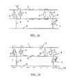
- Figures 1a and 1b show schematically the use of a track circuit fitted with a device for detecting rail breaks in common mode.
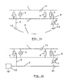
- Figures 2a to 2b represent schematically four versions of a device for detecting rail breaks.
- Figure 3 represents schematically a track circuit for detecting the presence of a train between two electrical joints, with their emitter and their receiver.
- Figure 4 represents schematically a track circuit for detecting a train, fitted with a device for detecting rail breaks.
- Figure 5 represents schematically a track section comprising two parallel tracks fitted with a device for detecting rail breaks, according to the invention.
- the present invention consists in the presence of a signal generator, especially a voltage source or a current source, placed either between the two rails of a railway track or on a common-mode link, and in the detection of the said signal indicating a rail fracture or break.
- a signal generator especially a voltage source or a current source
- Any combination of type of source (voltage or current) and type of detector (measurement of current or of voltage) can be included within the scope of the present invention.
- common mode is understood to signify a means that allows two rails to be joined. These common-mode means are usually constituted by appliances with mid-points, which are either themselves interconnected with the aid of connections or the mid-points of which are directed to earth.
- FIGS 1 and 2 describe schematically the principle of detection for a process and a device implemented according to a preferred embodiment. More detailed explanations can be found by reference to Figure 3 .
- a track circuit is constituted by rails 1 and 2, between which are arranged a source of AC voltage 3 at a frequency F1 and an impedance 4 equivalent to a given impedance at the said frequency of the source 3.
- This source generates a current which is preferably coded at a frequency that is lower the longer the section.
- the process according to the invention advantageously uses a system of coded signals to distinguish the traction current from the current for detecting rail breaks.
- appliances 5 impedance
- These appliances make it possible to achieve the common-mode link.
- appliances 5 are already fitted to track circuits and are, by virtue of this fact, used for the purpose of the invention.
- Such appliances 5 likewise exist in the case of a DC traction current, in order to ensure insulation of the track with respect to earth.
- the traction current is redirected via conductors 8 and from the mid-points of the said appliances 5 and a conductor 14 towards substations 15 ( Fig. 2b ).
- the electrical path formed by two conductors 8, and part of conductor 14 represent a common-mode connection 6.
- This connection 6 ( Fig. 2a or 2b ) will be used, according to the invention, to detect a rail break in the portion of track between the appliances 5.
- a device 7 capable of measuring the said current is arranged preferably in the connection 6 between an appliance 5 and either the conductor 14 or the earthing point 13, depending on the circumstances.
- This device 7 can be constituted by any instrument for measuring current known from the state of the art. It is, of course, configured to distinguish between the passage of a traction current and a current for detecting rail breaks at a frequency F1.
- the current I will pass via the circuit 12 ( Figure 1b ) and will cause an increase in the current (traction current + current due to the common mode) detected by the device 7. It is thus sufficient to detect this increase in current to be able to determine that a discontinuity in the rail 1 or the rail 2 has taken place and thus to detect a rail break in the section of track concerned.
- the tuning of the detection process should take account of the environment of the track (earthing, catenary etc.).
- the limitations on use depend on the type of traction, on the presence of an earthing or of a return to the substations and on the characteristics of the track.
- connection 6 can be made in various forms, depending on the characteristics of the track. There are essentially two possibilities, which are linked to the return of the traction current (AC or DC).
- the traction current can be drained by means of earthing points 13 for the rails of the track, in the case of a 25 kV, at 50 Hz AC traction voltage ( Fig. 2a ) (at regular distance), or through the presence of a conductor 14 which links a plurality of points along a track to a substation 15, which is essentially a common track insulation point for a number of points on the track in the case of a direct traction voltage ( Fig. 2b ).
- Figure 2a in fact describes a non-claimed version (AC voltage), which profits from the earthing points 13 which link the mid-points of the appliances 5.
- the appliances 5 of the invention are advantageously inductive impedances (windings) which exhibit a given value at the frequency F1 of the track circuit while at the same time forming a low impedance at low frequency. In the case appliances are already present on the track, serving as a return path for the traction current, these windings can be used in the process of the invention.
- Figure 2b represents the second non-claimed version in the case of a DC voltage: the conductor 14 is there essentially to drain the traction current towards the substation 15, but likewise serves as a connection 6 for implementing the process of the invention.
- connection consists in using the connection to detect the presence of a common-mode current, the connection being either an earthing link ( Fig. 2a ) or a link redirected towards the substations ( Fig. 2b ).
- a known method is then used to measure the current between a point, for example the mid-point of a winding of the appliance 5, and a point of the connection 6, which is, for example, the earthing or a point on a return path for the traction current towards the substations.
- the signal detected at the frequency F1 at a specific detector 7 present on this connection 6 signifies that a rail fracture has occurred on the section (block system) under consideration.
- the process of the invention may employ track circuits that are already present, such as the track circuits used to locate trains, which are separated by electrical joints.
- an electrical joint (referred to as an RX/TX joint) of the type shown in Figure 3 comprises two tuning units, TU.RX ("Tuning Unit - Receiver") and TU.TX ("Tuning Unit - Transmitter”) respectively, which are arranged between two rails 1 and 2, which connect the two rails and which are arranged at a distance of between 15 and 30 m from one another.
- the distance between the two adjacent joints can vary between a few hundred metres and one or two kilometres.
- Each joint thus separates the track into two sections 50 and 60, called “block systems", with an overlap zone 70, corresponding to the distance between the two units. Detection of the presence of a train is effected by means of electrical signals present in the circuits corresponding to the said block systems, at frequencies typical of each block system, this allowing electrical separation of two adjacent circuits.
- Figure 3 shows two electrical joints forming the limits of a track circuit.
- the unit 20 of the left-hand joint and the unit 21 of the right-hand joint are equivalent to capacitances at a first frequency F1.
- an AC source Tx
- the source Tx is in fact in series with the unit 20, while the unit 21 is provided with a receiver Rx in parallel, which essentially comprises a device for measuring the current in the track circuit.
- the track circuit corresponding to block system 50 is separated from the adjacent circuits 60 by virtue of the fact that the outer units 22 and 23 are equivalent to short circuits at the frequency F1.
- these units are by contrast equivalent to capacitances, in this way allowing detection of the presence of a train in the adjacent block system 60 by currents at this frequency F3.
- Detection of a train on the block system 50 is due to the fact that the axle 24 of this train forms in itself a short circuit between the rails 1 and 2. In reality, the axle exhibits a low impedance which can be likened to a short circuit, which will cause a drop in voltage in the receiver linked to unit 21, which is deactivated in this way. This deactivation thus corresponds to the detection of a train between units 20 and 21.
- a section of track monitored in accordance with the process of the invention may include several detecting track circuits. This allows the installation of appliances 5 with a mid-point close to a limited number of joints along the track, rather than close to each electrical joint.
- FIG. 5 A the invention is shown in Figure 5 .
- the measurement of current is performed on two essentially parallel pairs A and B of rails 1,2 and 1',2'.
- the two tracks A and B are equipped with track circuits for detecting trains, the said circuits being separated by electrical joints (20,22) and (21,23).
- the current-measuring device 7 is in the form of an instrument transformer (18,19,32), which allows a rail break to be detected in either of two block systems (30,31) belonging to either of the two parallel tracks.
- the detection of trains in the block systems 30 and 31 is performed by means of differential signals at different frequencies referred to as F1 and F2. Appliances 5,5' with a mid-point are present between the tuning units of the electrical joints.
- the impedance 18 consists in a self-induction coil with a mid-point earthed, for example, in the case of an AC voltage and acting as a primary of the instrument transformer.
- the mid-point can be connected to a cable which serves as a return connection towards the substations.
- detection of the two currents in the two circuits of the parallel tracks can be achieved with the aid of a single measurement appliance.
- the two windings 18 are used if an earthing is to be provided as shown in Figure 5 .
- At least one specific receiver 32 intended to detect the rail break is connected to the secondary 19 of the transformer.
- the receiver 32 detects a signal above a certain threshold corresponding to the determined frequency (filtering) and to the coding. This detection makes it possible to determine the block system or track in which there is an anomaly.
- receiver 32 per earthing point It is possible to use a single receiver 32 per earthing point, provided that it is equipped with means (of decoding for example) for distinguishing between a signal at frequency F1 and a signal at frequency F2.
- Two receivers 32 per earthing point will advantageously be installed, that is to say one receiver per frequency F1, F2. These receivers will be installed in parallel on the secondary winding 19.
- a rail break in one or the other of two block systems 30 and 31 is detected by a current-measuring device (18,19,32).
- the adjacent block sytems will be monitored by similar devices (18',19',32') linked to inductive connections 5' close to the adjacent joints.
- the presence of an earthing point in proximity to an electrical joint should participate in the common-mode conduction associated with a rail break in this section. It is consequently unnecessary to seek to detect this signal in the adjacent earthing points.
- the current sensor 18,19 and the detector 32 will preferably be incorporated into a single housing, into which there passes, for example, a conductor carrying the common-mode current. Detection by the detector 32 can be effected either at the track or at a distance.
Landscapes
- Engineering & Computer Science (AREA)
- Mechanical Engineering (AREA)
- Train Traffic Observation, Control, And Security (AREA)
- Investigating Or Analyzing Materials By The Use Of Ultrasonic Waves (AREA)
- Machines For Laying And Maintaining Railways (AREA)
- Geophysics And Detection Of Objects (AREA)
- Automobile Manufacture Line, Endless Track Vehicle, Trailer (AREA)
Claims (17)
- Verfahren zur Überwachung der Vollständigkeit von zwei Abschnitten von jeweils zwei Gleiswegen (A,B), wobei jeder Abschnitt einem Gleisweg entspricht, der aus jeweils zwei parallelen Schienen (1 und 2), (1',2') gebildet wird, zwischen denen einerseits ein Generator (3) oder Detektor (41) an einem Ende und eine Impedanz (4) am anderen Ende und andererseits ein Detektor (7) oder ein Generator (40) angeordnet sind, die in einem Gleichtakt-Verbindungsglied (6) angeordnet sind, welches Gleichtakt-Verbindungsglied (6) Einrichtungen mit Mittelpunkten umfaßt, die zwischen den Schienen angeordnet sind, welche Mittelpunkte zumindest durch Leiter (8) verbunden sind, und welcher Detektor (7,41) ein Messwandler ist, der eine erste Windung umfaßt, die als Primärwindung dient, eine zweite Windung (19), die als Sekundärwindung dient, und zumindest einen Empfänger (32),
welches Verfahren die folgenden Schritte umfaßt:- für jeden Abschnitt die Erzeugung eines Signals mit Hilfe des Generators mit einer bestimmten Frequenz und Eingabe desselben in den ersten Abschnitt,- für jeden Abschnitt die Aufnahme und Detektion des Signals mit der genannten Frequenz mit Hilfe des Detektors,- für jeden Abschnitt die Ausführung einer Verarbeitung des Signals und weitere Durchführung einer Vollständigkeitsdiagnose dieses Abschnitts,dadurch gekennzeichnet, dass die erste Windung (18) die Mittelpunkte zweier Einrichtungen (5) mit einem Mittelpunkt verbindet, der zu zwei verschiedenen Gleiswegen (A und B) gehört, wobei zumindest ein Empfänger (32) dazu vorgesehen ist, einen Strom mit einer ersten Frequenz (F1) zu detektieren, entsprechend einem ersten Gleisstromkreis, der auf den ersten Gleisweg (A) vorhanden ist, und zur Detektion eines Stroms mit einer zweiten Frequenz (F2), die einem zweiten Gleisstromkreis entspricht, der auf dem zweiten Gleisweg (B) vorhanden ist. - Verfahren gemäß Anspruch 1, dadurch gekennzeichnet,- dass ein Signal mit einer bestimmten Frequenz entsprechend einem Strom in einem ersten Stromkreis (10) entsprechend diesem Abschnitt erzeugt wird mit Hilfe einer Wechselspannungsquelle (3), die zwischen den Schienen (1 und 2) angeordnet ist,- und dass der Strom mit dieser Frequenz aufgenommen und detektiert wird mit Hilfe des Detektors (7), der in dem Gleichtaktverbindungsglied (6) angeordnet ist, in einem zusätzlichen Stromkreis (12), der gebildet wird durch zumindest eine Gleichtaktverbindung (6), die mit dem ersten Stromkreis verbunden ist.
- Verfahren gemäß Anspruch 1, dadurch gekennzeichnet,- dass ein Signal erzeugt wird durch eine Stromquelle (40) in einem zusätzlichen Stromkreis (12) mit einer bestimmten Frequenz, welche Stromquelle in der Gleichtaktverbindung (6) angeordnet ist,- und dass das Signal mit der genannten Frequenz aufgenommen und detektiert wird in einem ersten Stromkreis entsprechend dem Abschnitt (10) in Form einer Differenzspannung zwischen den zwei Schienen mit Hilfe des Detektors (41).
- Verfahren gemäß einem der vorhergehenden Ansprüche, dadurch gekennzeichnet, dass das Signal kodiert ist.
- Verfahren gemäß einem der vorhergehenden Ansprüche, dadurch gekennzeichnet, dass das Gleichtaktverbindungsglied (6) eine Erdungsverbindung ist, in dem Fall, dass der Fahrstrom ein Wechselstrom ist.
- Verfahren gemäß einem der Ansprüche 1 bis 4, dadurch gekennzeichnet, dass das Gleichtaktverbindungsglied (6) eine Verbindung ist, die als Rückleitung für den Fahrstrom in Richtung der Unterstationen ist, in dem Fall, dass der Fahrstrom ein Gleichstrom ist.
- Vorrichtung zur Überwachung der Vollständigkeit eines Abschnitts eines Gleisweges, vorzugsweise zur Detektion von Schienenbrüchen, umfassend zumindest:- eine Einrichtung (3) zur Erzeugung eines Signals, die zwischen zwei Schienen (1 und 2) des Gleiswegs angeordnet sind,- eine Impedanz (4), die mit den Schienen (1 und 2) in einem vorbestimmten Abstand von der Erzeugungseinrichtung verbunden ist,- Einrichtungen (5) mit Mittelpunkten, die zwischen den Schienen (1,2) und den Mittelpunkten angeordnet sind, welche zumindest durch Leiter (8) auf solche Weise verbunden sind, dass sie eine Gleichtaktverbindung (6) bilden,- eine Einrichtung (7) zur Detektion des Signals, die auf der Gleichtaktverbindung (6) angeordnet ist, welche Einrichtung (7) zur Detektion einen Messwandler umfasst, der eine erste Windung (18) als Primärwindung, eine zweite Windung (19) als Sekundärwindung und zumindest einen Empfänger (32) umfaßt, und- Einrichtungen zur Ausführung einer Verarbeitung dieses Signals und zur Weitergabe an eine Vollständigkeitsdiagnose dieses Abschnitts,dadurch gekennzeichnet, dass die erste Windung (18) die Mittelpunkte der zwei Einrichtungen (5) mit einem Mittelpunkt verbindet, der zu zwei unterschiedlichen Gleiswegen (A und B) gehört, wobei der zumindest eine Empfänger (32) dazu vorgesehen ist, einen Strom mit einer ersten Frequenz (F1) zu detektieren, entsprechend einem zweiten Gleisstromkreis, der auf dem zweiten Gleis (B) vorhanden ist.
- Vorrichtung gemäß Anspruch 7, bei welcher das Mittel zur Signalerzeugung aus einer Wechselspannungsquelle (3) besteht und die Einrichtung zur Signaldetektion aus einem Wechselspannungsdetektor (7) besteht.
- Vorrichtung zur Überwachung der Vollständigkeit eines Abschnitts eines Gleiswegs, vorzugsweise zur Detektion von Schienenbrüchen, umfassend zumindest:- eine Einrichtung (41) zur Detektion eines Signals, die zwischen den zwei Schienen (1 und 2) des Gleiswegs angeordnet ist, welche Einrichtung (41) zur Detektion einen Messwandler umfasst, mit einer ersten Windung (18) als Primärwindung, einer zweiten Windung (19) als Sekundärwindung, und zumindest einem Empfänger (32),- einer Impedanz (4), die mit den zwei Schienen (1 und 2) in einem vorbestimmten Abstand von der Detektionseinrichtung verbunden ist,- Einrichtungen (5) mit Mittelpunkten, die zwischen den Schienen und den Mittelpunkten angeordnet sind, welche Mittelpunkte zumindest durch Leiter (8) auf solche Weise verbunden sind, dass eine Gleichtaktverbindung (6) gebildet wird,- eine Einrichtung (40) zur Erzeugung des Signals, die auf der Gleichtaktverbindung (6) angeordnet ist,- Einrichtungen zur Verarbeitung des Signals und zur Weitergabe an die Vollständigkeitsdiagnose dieses Abschnitts,dadurch gekennzeichnet, dass die erste Windung (18) die Mittelpunkte der zwei Einrichtungen (5) mit einem Mittelpunkt verbindet, der zu zwei unterschiedlichen Gleiswegen (A und B) gehört, wobei der zumindest eine Empfänger (32) dazu vorgesehen ist, einen Strom mit einer ersten Frequenz (F1) zu detektieren, entsprechend einem ersten Gleisstromkreis auf dem ersten Gleis (A) und zur Detektion eines Stroms mit einer zweiten Frequenz (F2) entsprechend einem zweiten Gleisstromkreis auf dem zweiten Gleis (B).
- Vorrichtung gemäß Anspruch 9, bei welcher die Einrichtung zur Signaldetektion aus einem Wechselspannungsdetektor (41) besteht, und die Einrichtung zur Erzeugung eines Signals aus einer Wechselstromquelle (40) besteht.
- Vorrichtung gemäß einem der Ansprüche 7 bis 10, dadurch gekennzeichnet, dass die Gleichtaktverbindung (6) eine Erdungsverbindung mittels Erdungspunkten (13) umfaßt.
- Vorrichtung gemäß einem der Ansprüche 7 bis 10, dadurch gekennzeichnet, dass die Gleichtaktverbindung (6) einen Leiter (14) umfaßt, welcher die Rückleitung des Fahrstroms zu Unterstationen (15) bewirkt.
- Vorrichtung gemäß Anspruch 7 oder 8, dadurch gekennzeichnet, dass die Einrichtungen (5) mit einem Mittelpunkt Windungen mit einem Mittelpunkt darstellen.
- Vorrichtung gemäß Anspruch 8, bei welcher die Spannungsquelle (3) die Rolle eines Transmitters (Tx) eines Gleisstromkreises zur Detektion von Zügen spielt, und die Impedanz (4) die Rolle einer Einstelleinheit (21) in Verbindung mit dem Empfänger (Rx) eines Gleisstromkreises zur Detektion von Zügen spielt.
- Vorrichtung gemäß Anspruch 10, bei welcher der Differentialspannungsdetektor (41) die Rolle eines Empfängers (Rx) eines Gleisstromkreises für die Detektion von Zügen spielt, und die Impedanz (4) die Rolle einer Einstelleinheit (20) in Verbindung mit dem Transmitter (Tx) eines Gleisstromkreises für die Detektion von Zügen spielt.
- Vorrichtung gemäß Anspruch 14 oder 15, bei welcher die Gleisstromkreise von benachbarten Gleisstromkreisen durch Isolationsverbindungen getrennt sind.
- Vorrichtung gemäß Anspruch 14 oder 15, bei welcher die Gleisstromkreise von benachbarten Gleisstromkreisen durch elektrische Verbindungen getrennt sind.
Priority Applications (2)
| Application Number | Priority Date | Filing Date | Title |
|---|---|---|---|
| SI200331446T SI1348609T1 (sl) | 2002-03-27 | 2003-03-27 | Postopek in naprava za zaznavanje loma tirnice |
| EP03447067A EP1348609B1 (de) | 2002-03-27 | 2003-03-27 | Schienenbruchdetektionsverfahren und -Anlage |
Applications Claiming Priority (3)
| Application Number | Priority Date | Filing Date | Title |
|---|---|---|---|
| EP02447045 | 2002-03-27 | ||
| EP02447045A EP1348608A1 (de) | 2002-03-27 | 2002-03-27 | Schienenbruchdetektionsverfahren und -Anlage |
| EP03447067A EP1348609B1 (de) | 2002-03-27 | 2003-03-27 | Schienenbruchdetektionsverfahren und -Anlage |
Publications (2)
| Publication Number | Publication Date |
|---|---|
| EP1348609A1 EP1348609A1 (de) | 2003-10-01 |
| EP1348609B1 true EP1348609B1 (de) | 2008-10-22 |
Family
ID=27798978
Family Applications (2)
| Application Number | Title | Priority Date | Filing Date |
|---|---|---|---|
| EP02447045A Withdrawn EP1348608A1 (de) | 2002-03-27 | 2002-03-27 | Schienenbruchdetektionsverfahren und -Anlage |
| EP03447067A Expired - Lifetime EP1348609B1 (de) | 2002-03-27 | 2003-03-27 | Schienenbruchdetektionsverfahren und -Anlage |
Family Applications Before (1)
| Application Number | Title | Priority Date | Filing Date |
|---|---|---|---|
| EP02447045A Withdrawn EP1348608A1 (de) | 2002-03-27 | 2002-03-27 | Schienenbruchdetektionsverfahren und -Anlage |
Country Status (9)
| Country | Link |
|---|---|
| EP (2) | EP1348608A1 (de) |
| KR (1) | KR101044681B1 (de) |
| CN (1) | CN100441460C (de) |
| AT (1) | ATE411930T1 (de) |
| DE (1) | DE60324216D1 (de) |
| DK (1) | DK1348609T3 (de) |
| ES (1) | ES2315474T3 (de) |
| PT (1) | PT1348609E (de) |
| SI (1) | SI1348609T1 (de) |
Families Citing this family (19)
| Publication number | Priority date | Publication date | Assignee | Title |
|---|---|---|---|---|
| KR100730372B1 (ko) * | 2005-06-14 | 2007-06-19 | 주식회사 혁신전공사 | 철도용 신호제어 시스템 및 그 방법 |
| NL1033153C2 (nl) * | 2005-12-22 | 2008-01-08 | Voestalpine Railpro B V | ES-las kwaliteitbewakingsysteem. |
| DE102006009962B3 (de) * | 2005-12-23 | 2007-05-31 | Areva Np Gmbh | Verfahren und Einrichtung zum Überwachen eines Gleises |
| US7226021B1 (en) * | 2005-12-27 | 2007-06-05 | General Electric Company | System and method for detecting rail break or vehicle |
| DE102006024692B4 (de) * | 2006-05-19 | 2008-05-29 | Siemens Ag | Verfahren und Vorrichtung zur Detektion des Belegt- oder Freizustandes eines Gleisabschnittes |
| US7954770B2 (en) * | 2006-12-15 | 2011-06-07 | General Electric Company | Methods and system for jointless track circuits using passive signaling |
| CN101607565B (zh) * | 2008-06-16 | 2013-06-19 | 唐德尧 | 一种钢轨裂纹地面在线监测装置及其地面在线监测方法 |
| CN102416970B (zh) * | 2011-10-12 | 2013-11-06 | 北京安通伟业铁路工务技术有限公司 | 一种采用钢轨断裂在线监测系统的敲击检测方法 |
| SG11201405197WA (en) * | 2012-04-23 | 2014-09-26 | Univ Nanyang Tech | Method and apparatus for detecting railway system defects |
| CZ304457B6 (cs) * | 2012-08-20 | 2014-05-14 | Eurosignal A.S. | Zařízení pro indikaci zlomené kolejnice |
| CN106442647A (zh) * | 2016-10-27 | 2017-02-22 | 北京国兴力德新材料技术有限公司 | 一种铁路道岔尖轨伤损监测装置及其方法 |
| CN107985344B (zh) * | 2017-10-19 | 2021-02-09 | 北京全路通信信号研究设计院集团有限公司 | 断轨检测方法及装置 |
| CN107914737B (zh) * | 2017-10-19 | 2021-02-09 | 北京全路通信信号研究设计院集团有限公司 | 断轨检测方法及装置 |
| CN108008210B (zh) * | 2017-10-19 | 2021-03-23 | 北京全路通信信号研究设计院集团有限公司 | 断轨检测方法及装置 |
| KR101949952B1 (ko) * | 2018-10-05 | 2019-05-21 | 벽산파워 주식회사 | 궤도회로 불평형 모니터링 방법 |
| CN109677447B (zh) * | 2018-12-24 | 2024-03-29 | 卡斯柯信号有限公司 | 一种基于二乘二取二架构的多制式轨道信号采集系统 |
| CN111661105B (zh) * | 2019-10-17 | 2021-06-01 | 东莞理工学院 | 一种轨道交通故障诊断用轨道焊缝检测装置 |
| RU2748826C1 (ru) * | 2020-11-23 | 2021-05-31 | Федеральное государственное автономное образовательное учреждение высшего образования "Российский университет транспорта" (ФГАОУ ВО РУТ (МИИТ), РУТ (МИИТ) | Устройство для контроля излома рельсов на участках с электротягой переменного тока |
| CN113514685B (zh) * | 2021-07-26 | 2022-11-08 | 中车株洲电力机车研究所有限公司 | 列车轨道感应电压的地面测试装置及其测试方法 |
Family Cites Families (12)
| Publication number | Priority date | Publication date | Assignee | Title |
|---|---|---|---|---|
| US3924461A (en) * | 1974-08-20 | 1975-12-09 | Harris A Stover | Monitoring system for detecting defective rails or road beds |
| US4005601A (en) * | 1975-08-29 | 1977-02-01 | Amac, Inc. | Apparatus for detecting rail discontinuities |
| IT1073468B (it) * | 1977-03-18 | 1985-04-17 | Wabco Westinghouse Spa | Dispositivo di protezione per apparecchiature di segnalamento ferro viario |
| US4117529A (en) * | 1977-03-23 | 1978-09-26 | Westinghouse Air Brake Company | Broken rail detecting track circuits |
| AU6888181A (en) * | 1980-04-08 | 1981-10-15 | Gec-General Signal Ltd. | Broken power rail detection |
| IT1151495B (it) * | 1980-04-18 | 1986-12-17 | Ansaldo Sa | Rilevatore di squilibrio della corrente armonica di trazione nei circuiti di binario |
| CN88203203U (zh) * | 1988-02-04 | 1988-10-19 | 哈尔滨铁路局工业处哈尔滨通信信号器材厂 | 通用机车信号检测仪 |
| DE50015765D1 (de) * | 1999-02-12 | 2009-12-03 | Plasser Bahnbaumasch Franz | Verfahren zum Aufmessen eines Gleises |
| US6262573B1 (en) * | 1999-09-17 | 2001-07-17 | General Electric Company | Electromagnetic system for railroad track crack detection and traction enhancement |
| DE10022636A1 (de) * | 2000-04-28 | 2001-10-31 | Siemens Ag | Vermaschter Gleisstromkreis |
| CN2457601Y (zh) * | 2000-12-28 | 2001-10-31 | 洛阳市瀍河环星电子标牌厂 | 双零度探头钢轨探伤仪 |
| CN2473089Y (zh) * | 2001-04-28 | 2002-01-23 | 上海理工大学附属二厂 | 轨道综合测量仪 |
-
2002
- 2002-03-27 EP EP02447045A patent/EP1348608A1/de not_active Withdrawn
-
2003
- 2003-03-27 DK DK03447067T patent/DK1348609T3/da active
- 2003-03-27 DE DE60324216T patent/DE60324216D1/de not_active Expired - Lifetime
- 2003-03-27 CN CNB031082815A patent/CN100441460C/zh not_active Expired - Fee Related
- 2003-03-27 PT PT03447067T patent/PT1348609E/pt unknown
- 2003-03-27 SI SI200331446T patent/SI1348609T1/sl unknown
- 2003-03-27 KR KR1020030019106A patent/KR101044681B1/ko not_active Expired - Fee Related
- 2003-03-27 EP EP03447067A patent/EP1348609B1/de not_active Expired - Lifetime
- 2003-03-27 ES ES03447067T patent/ES2315474T3/es not_active Expired - Lifetime
- 2003-03-27 AT AT03447067T patent/ATE411930T1/de active
Also Published As
| Publication number | Publication date |
|---|---|
| PT1348609E (pt) | 2008-12-22 |
| EP1348609A1 (de) | 2003-10-01 |
| EP1348608A1 (de) | 2003-10-01 |
| DE60324216D1 (de) | 2008-12-04 |
| ATE411930T1 (de) | 2008-11-15 |
| SI1348609T1 (sl) | 2009-02-28 |
| KR20030078030A (ko) | 2003-10-04 |
| DK1348609T3 (da) | 2009-02-09 |
| CN100441460C (zh) | 2008-12-10 |
| CN1451577A (zh) | 2003-10-29 |
| HK1058341A1 (zh) | 2004-05-14 |
| ES2315474T3 (es) | 2009-04-01 |
| KR101044681B1 (ko) | 2011-06-28 |
Similar Documents
| Publication | Publication Date | Title |
|---|---|---|
| EP1348609A1 (de) | Schienenbruchdetektionsverfahren und -Anlage | |
| US6779761B2 (en) | Broken rail detection | |
| CA1194120A (en) | Circuit for detecting unbalance of the traction current in a track circuit | |
| US10093329B2 (en) | Track circuit mechanical joint integrity checker | |
| EP3196095B1 (de) | System und verfahren zur erkennung gebrochener schienen auf einem gleis | |
| US20250229814A1 (en) | Broken rail detector | |
| JPS6137576A (ja) | 交流電化式鉄道用軌条回路 | |
| US12459551B2 (en) | Broken rail detector | |
| HK1058341B (en) | Process and installation for detecting a rail break | |
| US20240217566A1 (en) | Rail Bond Monitor | |
| WO2021205944A1 (ja) | 保全装置、保全システム及び保全方法 | |
| RU2770322C1 (ru) | Устройство для определения схода колесных пар подвижного состава или волочащейся металлической детали и датчик контроля схода подвижного состава | |
| Huemmer | Interference-free track vacancy detection | |
| Vora et al. | Audio Frequency Track Circuit | |
| Pinte et al. | HOW TO REDUCE THE IMPACT OF TRACK CIRCUIT FAILURES | |
| ES2320517B1 (es) | Metodo detector de ocupacion de circuitos de via de ferrocarril, y dispositivo correspondiente. | |
| JPS6026749B2 (ja) | 無絶縁軌道回路の信号送受電方式 | |
| JPH02234875A (ja) | 無絶縁軌道回路 |
Legal Events
| Date | Code | Title | Description |
|---|---|---|---|
| PUAI | Public reference made under article 153(3) epc to a published international application that has entered the european phase |
Free format text: ORIGINAL CODE: 0009012 |
|
| AK | Designated contracting states |
Kind code of ref document: A1 Designated state(s): AT BE BG CH CY CZ DE DK EE ES FI FR GB GR HU IE IT LI LU MC NL PT SE SI SK TR |
|
| AX | Request for extension of the european patent |
Extension state: AL LT LV MK RO |
|
| 17P | Request for examination filed |
Effective date: 20040223 |
|
| AKX | Designation fees paid |
Designated state(s): AT BE BG CH CY CZ DE DK EE ES FI FR GB GR HU IE IT LI LU MC NL PT SE SI SK TR |
|
| 17Q | First examination report despatched |
Effective date: 20070216 |
|
| GRAP | Despatch of communication of intention to grant a patent |
Free format text: ORIGINAL CODE: EPIDOSNIGR1 |
|
| RBV | Designated contracting states (corrected) |
Designated state(s): AT BE BG CH CY CZ DE DK EE ES FI FR GB GR HU IE IT LI LU MC NL PT RO SE SI SK TR |
|
| GRAS | Grant fee paid |
Free format text: ORIGINAL CODE: EPIDOSNIGR3 |
|
| GRAA | (expected) grant |
Free format text: ORIGINAL CODE: 0009210 |
|
| AK | Designated contracting states |
Kind code of ref document: B1 Designated state(s): AT BE BG CH CY CZ DE DK EE ES FI FR GB GR HU IE IT LI LU MC NL PT RO SE SI SK TR |
|
| REG | Reference to a national code |
Ref country code: GB Ref legal event code: FG4D |
|
| REG | Reference to a national code |
Ref country code: CH Ref legal event code: EP |
|
| REG | Reference to a national code |
Ref country code: IE Ref legal event code: FG4D |
|
| REF | Corresponds to: |
Ref document number: 60324216 Country of ref document: DE Date of ref document: 20081204 Kind code of ref document: P |
|
| REG | Reference to a national code |
Ref country code: RO Ref legal event code: EPE |
|
| REG | Reference to a national code |
Ref country code: GR Ref legal event code: EP Ref document number: 20080403212 Country of ref document: GR |
|
| REG | Reference to a national code |
Ref country code: PT Ref legal event code: SC4A Free format text: AVAILABILITY OF NATIONAL TRANSLATION Effective date: 20081210 |
|
| REG | Reference to a national code |
Ref country code: SE Ref legal event code: TRGR |
|
| REG | Reference to a national code |
Ref country code: DK Ref legal event code: T3 |
|
| REG | Reference to a national code |
Ref country code: ES Ref legal event code: FG2A Ref document number: 2315474 Country of ref document: ES Kind code of ref document: T3 |
|
| PGFP | Annual fee paid to national office [announced via postgrant information from national office to epo] |
Ref country code: EE Payment date: 20090306 Year of fee payment: 7 Ref country code: IE Payment date: 20090225 Year of fee payment: 7 |
|
| PGFP | Annual fee paid to national office [announced via postgrant information from national office to epo] |
Ref country code: SI Payment date: 20090218 Year of fee payment: 7 Ref country code: SK Payment date: 20090227 Year of fee payment: 7 |
|
| PLBE | No opposition filed within time limit |
Free format text: ORIGINAL CODE: 0009261 |
|
| STAA | Information on the status of an ep patent application or granted ep patent |
Free format text: STATUS: NO OPPOSITION FILED WITHIN TIME LIMIT |
|
| 26N | No opposition filed |
Effective date: 20090723 |
|
| PGFP | Annual fee paid to national office [announced via postgrant information from national office to epo] |
Ref country code: MC Payment date: 20090216 Year of fee payment: 7 |
|
| PG25 | Lapsed in a contracting state [announced via postgrant information from national office to epo] |
Ref country code: MC Free format text: LAPSE BECAUSE OF NON-PAYMENT OF DUE FEES Effective date: 20100331 |
|
| REG | Reference to a national code |
Ref country code: SK Ref legal event code: MM4A Ref document number: E 4299 Country of ref document: SK Effective date: 20100327 |
|
| REG | Reference to a national code |
Ref country code: EE Ref legal event code: MM4A Ref document number: E002683 Country of ref document: EE Effective date: 20100331 |
|
| REG | Reference to a national code |
Ref country code: IE Ref legal event code: MM4A |
|
| REG | Reference to a national code |
Ref country code: SI Ref legal event code: KO00 Effective date: 20101115 |
|
| PG25 | Lapsed in a contracting state [announced via postgrant information from national office to epo] |
Ref country code: IE Free format text: LAPSE BECAUSE OF NON-PAYMENT OF DUE FEES Effective date: 20100329 Ref country code: EE Free format text: LAPSE BECAUSE OF NON-PAYMENT OF DUE FEES Effective date: 20100331 |
|
| PG25 | Lapsed in a contracting state [announced via postgrant information from national office to epo] |
Ref country code: SK Free format text: LAPSE BECAUSE OF NON-PAYMENT OF DUE FEES Effective date: 20100327 Ref country code: SI Free format text: LAPSE BECAUSE OF NON-PAYMENT OF DUE FEES Effective date: 20100328 |
|
| PG25 | Lapsed in a contracting state [announced via postgrant information from national office to epo] |
Ref country code: CY Free format text: LAPSE BECAUSE OF FAILURE TO SUBMIT A TRANSLATION OF THE DESCRIPTION OR TO PAY THE FEE WITHIN THE PRESCRIBED TIME-LIMIT Effective date: 20081022 |
|
| REG | Reference to a national code |
Ref country code: FR Ref legal event code: PLFP Year of fee payment: 14 |
|
| REG | Reference to a national code |
Ref country code: FR Ref legal event code: PLFP Year of fee payment: 15 |
|
| REG | Reference to a national code |
Ref country code: FR Ref legal event code: PLFP Year of fee payment: 16 |
|
| PGFP | Annual fee paid to national office [announced via postgrant information from national office to epo] |
Ref country code: PT Payment date: 20200221 Year of fee payment: 18 Ref country code: AT Payment date: 20200320 Year of fee payment: 18 Ref country code: HU Payment date: 20200317 Year of fee payment: 18 Ref country code: BG Payment date: 20200323 Year of fee payment: 18 Ref country code: FI Payment date: 20200320 Year of fee payment: 18 Ref country code: DE Payment date: 20200320 Year of fee payment: 18 Ref country code: GB Payment date: 20200323 Year of fee payment: 18 Ref country code: RO Payment date: 20200225 Year of fee payment: 18 Ref country code: SE Payment date: 20200323 Year of fee payment: 18 Ref country code: GR Payment date: 20200312 Year of fee payment: 18 Ref country code: DK Payment date: 20200324 Year of fee payment: 18 Ref country code: NL Payment date: 20200319 Year of fee payment: 18 |
|
| PGFP | Annual fee paid to national office [announced via postgrant information from national office to epo] |
Ref country code: CH Payment date: 20200319 Year of fee payment: 18 Ref country code: CZ Payment date: 20200319 Year of fee payment: 18 Ref country code: LU Payment date: 20200324 Year of fee payment: 18 Ref country code: BE Payment date: 20200319 Year of fee payment: 18 |
|
| PGFP | Annual fee paid to national office [announced via postgrant information from national office to epo] |
Ref country code: TR Payment date: 20200327 Year of fee payment: 18 Ref country code: FR Payment date: 20200319 Year of fee payment: 18 |
|
| PGFP | Annual fee paid to national office [announced via postgrant information from national office to epo] |
Ref country code: IT Payment date: 20200318 Year of fee payment: 18 |
|
| REG | Reference to a national code |
Ref country code: ES Ref legal event code: FD2A Effective date: 20210805 |
|
| REG | Reference to a national code |
Ref country code: DE Ref legal event code: R119 Ref document number: 60324216 Country of ref document: DE |
|
| REG | Reference to a national code |
Ref country code: FI Ref legal event code: MAE |
|
| PG25 | Lapsed in a contracting state [announced via postgrant information from national office to epo] |
Ref country code: CZ Free format text: LAPSE BECAUSE OF NON-PAYMENT OF DUE FEES Effective date: 20210327 Ref country code: FI Free format text: LAPSE BECAUSE OF NON-PAYMENT OF DUE FEES Effective date: 20210327 |
|
| REG | Reference to a national code |
Ref country code: CH Ref legal event code: PL |
|
| REG | Reference to a national code |
Ref country code: DK Ref legal event code: EBP Effective date: 20210331 |
|
| REG | Reference to a national code |
Ref country code: NL Ref legal event code: MM Effective date: 20210401 |
|
| REG | Reference to a national code |
Ref country code: AT Ref legal event code: MM01 Ref document number: 411930 Country of ref document: AT Kind code of ref document: T Effective date: 20210327 |
|
| GBPC | Gb: european patent ceased through non-payment of renewal fee |
Effective date: 20210327 |
|
| PG25 | Lapsed in a contracting state [announced via postgrant information from national office to epo] |
Ref country code: ES Free format text: LAPSE BECAUSE OF NON-PAYMENT OF DUE FEES Effective date: 20200328 Ref country code: PT Free format text: LAPSE BECAUSE OF NON-PAYMENT OF DUE FEES Effective date: 20210927 Ref country code: RO Free format text: LAPSE BECAUSE OF NON-PAYMENT OF DUE FEES Effective date: 20210327 |
|
| REG | Reference to a national code |
Ref country code: BE Ref legal event code: MM Effective date: 20210331 |
|
| PG25 | Lapsed in a contracting state [announced via postgrant information from national office to epo] |
Ref country code: AT Free format text: LAPSE BECAUSE OF NON-PAYMENT OF DUE FEES Effective date: 20210327 Ref country code: BG Free format text: LAPSE BECAUSE OF NON-PAYMENT OF DUE FEES Effective date: 20210930 Ref country code: CH Free format text: LAPSE BECAUSE OF NON-PAYMENT OF DUE FEES Effective date: 20210331 Ref country code: LI Free format text: LAPSE BECAUSE OF NON-PAYMENT OF DUE FEES Effective date: 20210331 Ref country code: LU Free format text: LAPSE BECAUSE OF NON-PAYMENT OF DUE FEES Effective date: 20210327 Ref country code: NL Free format text: LAPSE BECAUSE OF NON-PAYMENT OF DUE FEES Effective date: 20210401 Ref country code: FR Free format text: LAPSE BECAUSE OF NON-PAYMENT OF DUE FEES Effective date: 20210331 Ref country code: HU Free format text: LAPSE BECAUSE OF NON-PAYMENT OF DUE FEES Effective date: 20210328 Ref country code: GB Free format text: LAPSE BECAUSE OF NON-PAYMENT OF DUE FEES Effective date: 20210327 Ref country code: SE Free format text: LAPSE BECAUSE OF NON-PAYMENT OF DUE FEES Effective date: 20210328 Ref country code: DE Free format text: LAPSE BECAUSE OF NON-PAYMENT OF DUE FEES Effective date: 20211001 |
|
| PG25 | Lapsed in a contracting state [announced via postgrant information from national office to epo] |
Ref country code: GR Free format text: LAPSE BECAUSE OF NON-PAYMENT OF DUE FEES Effective date: 20211008 |
|
| PG25 | Lapsed in a contracting state [announced via postgrant information from national office to epo] |
Ref country code: IT Free format text: LAPSE BECAUSE OF NON-PAYMENT OF DUE FEES Effective date: 20210327 Ref country code: DK Free format text: LAPSE BECAUSE OF NON-PAYMENT OF DUE FEES Effective date: 20210331 |
|
| PG25 | Lapsed in a contracting state [announced via postgrant information from national office to epo] |
Ref country code: BE Free format text: LAPSE BECAUSE OF NON-PAYMENT OF DUE FEES Effective date: 20210331 |
|
| PG25 | Lapsed in a contracting state [announced via postgrant information from national office to epo] |
Ref country code: TR Free format text: LAPSE BECAUSE OF NON-PAYMENT OF DUE FEES Effective date: 20210327 |