EP1348614B1 - Montageverfahren für ein Kraftfahrzeug-Ausstattungsmodul und ein Karrosserieteil, und Anordnung für eine derartige Montage - Google Patents
Montageverfahren für ein Kraftfahrzeug-Ausstattungsmodul und ein Karrosserieteil, und Anordnung für eine derartige Montage Download PDFInfo
- Publication number
- EP1348614B1 EP1348614B1 EP03006056A EP03006056A EP1348614B1 EP 1348614 B1 EP1348614 B1 EP 1348614B1 EP 03006056 A EP03006056 A EP 03006056A EP 03006056 A EP03006056 A EP 03006056A EP 1348614 B1 EP1348614 B1 EP 1348614B1
- Authority
- EP
- European Patent Office
- Prior art keywords
- equipment module
- structural element
- casing element
- module
- casing
- Prior art date
- Legal status (The legal status is an assumption and is not a legal conclusion. Google has not performed a legal analysis and makes no representation as to the accuracy of the status listed.)
- Expired - Lifetime
Links
- 238000000034 method Methods 0.000 title claims abstract description 26
- 238000000926 separation method Methods 0.000 claims description 4
- 230000000295 complement effect Effects 0.000 claims description 2
- 238000005253 cladding Methods 0.000 description 19
- 238000006073 displacement reaction Methods 0.000 description 4
- 210000004027 cell Anatomy 0.000 description 1
- 210000000078 claw Anatomy 0.000 description 1
- 239000013536 elastomeric material Substances 0.000 description 1
Images




Classifications
-
- B—PERFORMING OPERATIONS; TRANSPORTING
- B60—VEHICLES IN GENERAL
- B60S—SERVICING, CLEANING, REPAIRING, SUPPORTING, LIFTING, OR MANOEUVRING OF VEHICLES, NOT OTHERWISE PROVIDED FOR
- B60S1/00—Cleaning of vehicles
- B60S1/02—Cleaning windscreens, windows or optical devices
- B60S1/56—Cleaning windscreens, windows or optical devices specially adapted for cleaning other parts or devices than front windows or windscreens
- B60S1/58—Cleaning windscreens, windows or optical devices specially adapted for cleaning other parts or devices than front windows or windscreens for rear windows
- B60S1/583—Cleaning windscreens, windows or optical devices specially adapted for cleaning other parts or devices than front windows or windscreens for rear windows including wiping devices
-
- B—PERFORMING OPERATIONS; TRANSPORTING
- B62—LAND VEHICLES FOR TRAVELLING OTHERWISE THAN ON RAILS
- B62D—MOTOR VEHICLES; TRAILERS
- B62D65/00—Designing, manufacturing, e.g. assembling, facilitating disassembly, or structurally modifying motor vehicles or trailers, not otherwise provided for
- B62D65/02—Joining sub-units or components to, or positioning sub-units or components with respect to, body shell or other sub-units or components
- B62D65/16—Joining sub-units or components to, or positioning sub-units or components with respect to, body shell or other sub-units or components the sub-units or components being exterior fittings, e.g. bumpers, lights, wipers, exhausts
-
- B—PERFORMING OPERATIONS; TRANSPORTING
- B60—VEHICLES IN GENERAL
- B60S—SERVICING, CLEANING, REPAIRING, SUPPORTING, LIFTING, OR MANOEUVRING OF VEHICLES, NOT OTHERWISE PROVIDED FOR
- B60S1/00—Cleaning of vehicles
- B60S1/02—Cleaning windscreens, windows or optical devices
- B60S1/04—Wipers or the like, e.g. scrapers
- B60S1/043—Attachment of the wiper assembly to the vehicle
- B60S1/0441—Attachment of the wiper assembly to the vehicle characterised by the attachment means
-
- B—PERFORMING OPERATIONS; TRANSPORTING
- B60—VEHICLES IN GENERAL
- B60S—SERVICING, CLEANING, REPAIRING, SUPPORTING, LIFTING, OR MANOEUVRING OF VEHICLES, NOT OTHERWISE PROVIDED FOR
- B60S1/00—Cleaning of vehicles
- B60S1/02—Cleaning windscreens, windows or optical devices
- B60S1/04—Wipers or the like, e.g. scrapers
- B60S1/043—Attachment of the wiper assembly to the vehicle
- B60S1/0441—Attachment of the wiper assembly to the vehicle characterised by the attachment means
- B60S1/0447—Attachment of the wiper assembly to the vehicle characterised by the attachment means non-screw fixation, (e.g. snap-in, bayonnet-type..)
-
- B—PERFORMING OPERATIONS; TRANSPORTING
- B60—VEHICLES IN GENERAL
- B60S—SERVICING, CLEANING, REPAIRING, SUPPORTING, LIFTING, OR MANOEUVRING OF VEHICLES, NOT OTHERWISE PROVIDED FOR
- B60S1/00—Cleaning of vehicles
- B60S1/02—Cleaning windscreens, windows or optical devices
- B60S1/04—Wipers or the like, e.g. scrapers
- B60S1/043—Attachment of the wiper assembly to the vehicle
- B60S1/0441—Attachment of the wiper assembly to the vehicle characterised by the attachment means
- B60S1/045—Attachment of the wiper assembly to the vehicle characterised by the attachment means having a pre-attachment device (i.e. to hold elements in position during mounting)
Definitions
- the invention relates to a method of assembling an equipment module and a cladding element on a structural element of a motor vehicle.
- the invention relates more particularly to a method of assembling an equipment module and a cladding element on a structural element of a motor vehicle, of the type which comprises a step of fixing the equipment module. on one side of the structural element and a step of fixing the covering element on said face.
- the equipment module and the cladding element are assembled on the vehicle structure element at different times and independently of one another.
- each element takes a certain time, in particular as regards their positioning relative to a structural element of the vehicle, and then their attachment. Positioning is generally performed by means of a mounting robot whose arm must make a rapid movement of the element from a storage location to the vehicle, then a slower movement for the positioning of the vehicle. element with respect to the structural element.
- the equipment module and the covering element are each fixed on the same structural element of the vehicle.
- the item of equipment which is for example a geared motor for driving a hatchback wiper, generates vibrations and therefore noise.
- the covering element makes it possible to isolate the interior passenger compartment from the noise.
- the trim element must be separated from the equipment module.
- the invention proposes a method of the type described above, characterized in that it comprises an initial step of temporary attachment of the equipment module with the dressing element, and a positioning step of the together formed by the equipment module and the cladding element, with respect to the structural element.
- the invention also proposes an arrangement for fixing an equipment module and a cladding element on a face of a structural element of a motor vehicle, for the implementation of a method such as as described above, of the type in which the equipment module is interposed between said face of the structural element and the cladding element, characterized in that the equipment module and the cladding element are connected by means that allow the equipment module to be secured temporarily to the cladding element before they are fastened to the structural element.
- the direction from back to front will also be adopted as the longitudinal direction and from right to left with reference to FIG. 1A.
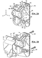
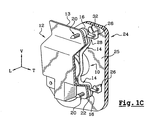
- FIGS. 1A to 1C show an equipment module 10, which is for example a geared motor for driving a device for wiping the window pane of a motor vehicle tailgate (not shown).
- the equipment module 10 is fixed on an internal vertical face 13 of a structural element 12 of the tailgate.
- the equipment module 10 For attachment to the structural element 12, the equipment module 10 comprises fastening tabs 14, which here are three in number, each of which extends substantially in a vertical transverse plane from the equipment module 10 , and whose free end 16 of each fastening lug 14 comprises a through hole 18 of a fixing screw 20 of longitudinal axis A.
- the equipment module 10 is capable of producing vibrations which, when they are transmitted to the structural element 12, are the source of an often unpleasant noise. Therefore, in known manner, a damper 22 or "silent-block", which is made of an elastomeric material, is interposed between the free end 16 of each lug 14 and the inner face 13 of the structural element 12.
- the equipment module 10 is covered by a cladding element 24, or lining which is also fixed on the inner face 13 of the structural element 12, for example by elastic interlocking.
- the two elements In order to prevent the vibrations produced by the equipment module 10 from being transmitted to the covering element 24, the two elements must each be fixed on the structural element 12, but the equipment module 10 either separate or isolated from the covering element 24.
- the equipment module 10 and the cladding element 24 comprise means which make it possible to temporarily secure them, with a view to their simultaneous positioning with respect to the structural element 12. , then to dissociate them.
- These temporary securing means consist of tabs 26 which extend longitudinally forwards from an outer face 25 of the covering element 24 which is opposite to the internal face 13 of the structural element 12, and each cooperates with a finger 28 of the equipment module 10 for temporary joining.
- Each lug 26 consists of an elastic gripper 27 whose two branches 30 extend longitudinally forwards, so that the gripper 27 opens, or for an elastic interlocking of the fingers 28 to allow the attachment of the equipment module. 10 with the covering element 24, or to release the fingers 28 to allow separation of the equipment module 10 from the covering element 24.
- the interlocking or disengagement of the equipment module 10 is effected by a longitudinal displacement of the equipment module 10 respectively forward or backward.
- the fingers 28 are of generally cylindrical shape and each extends from the equipment module 10 in a transverse plane parallel to the outer face 25 of the covering element 24.
- the lugs 26 and the associated fingers 28 must also ensure a positioning of the equipment module 10 on the covering element 24.
- the fingers 28 are supported longitudinally against the bottom of the associated clamp 27, so as to position the equipment module 10 longitudinally.
- the tabs 26 are three in number, and at least two fingers 28 are of different general orientations from one another, which allows to position the equipment module 10, vertically and transversely, and to orienting it about a longitudinal axis, that is to say in a plane parallel to the outer face 25 of the covering element 24.
- two fingers 28 are parallel to the transverse direction "T", and a third finger 28 'is substantially vertical.
- the covering element 24 can interfere with access to the fixing screws 20.
- the covering element 24 has an access hole 32 located opposite each through hole 18.
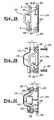
- the assembly of the equipment module 10 and the covering element 24 on the structural element 12 is made according to a method according to the teachings of the invention, which comprises an initial step, represented in FIGS. 1A and 2A. , from temporary joining of the equipment module 10 with the covering element 24.
- This temporary securing step consists in fitting the fingers 28 in the associated clamps 27 by a longitudinal displacement towards the rear of the covering element 24 with respect to the equipment module 10.
- the method comprises a second step, represented in FIGS. 1B and 2B, of positioning of the assembly thus formed by the equipment module 10 and the covering element 24, with respect to the structural element 12.
- the method comprises a third step, shown in FIGS. 1C and 2C, for fixing the equipment module 10 and the covering element 24 on the structural element 12.
- the equipment module 10 and the covering element 24 are positioned relative to the structural element 12, the equipment module 10 is remote from its final fixing position on the inner face 13 of the element 12 with a longitudinal clearance "j", while the covering element 24 is positioned longitudinally in its final fixing position on the same inner face 13.
- the equipment module 10 moves longitudinally forwards with respect to the covering element 24, until it disengages from the covering element 24, that is to say until the fingers 28 no longer cooperate with the tabs 26.
- the assembly method also comprises a step of separating the equipment module 10 from the covering element 24, which is simultaneous with the third fixing step.
- the covering element 24 is not moved longitudinally with respect to the structural element 12.
- the equipment module 10 and the cladding element 24 are separated by the game "j".
- the value of the set "j" is greater or smaller depending on the dimensions of the clamps 27 and associated fingers 28, and the space between the equipment module 10 and the covering element 24 is unused and it reduces the volume inside the vehicle interior.
- the uncoupling step consists in transversely displacing the covering element 24 with respect to the equipment module 10.
- the branches 30 of the clamps 27 all extend transversely to the right, and they are preferably positioned in the same transverse plane parallel to the external face 25 of the covering element 24.
- the fingers 28 are of longitudinal orientation, which makes it possible to position the equipment module 10 in a plane parallel to the outer face 25 of the covering element 24.
- each finger 28 is extended by a flat rib 34 which is extends parallel to the outer face 25 of the cladding element 24, and whose rear longitudinal end face 34a rests against a transverse face 36 of the lug 26 associated.
- the assembly method comprises a first step, represented in FIGS. 3A and 4A, of temporary attachment of the equipment module 10 and the covering element 24.
- This first step consists in fit the fingers 28 in the associated clips 27 by a transverse displacement to the left of the covering element 24 with respect to the equipment module 10.
- the method comprises a second step, represented in FIGS. 3B and 4B, for positioning the assembly formed by the wiping module 10 and the covering element 24 with respect to the structural element 12, so that the the equipment module bears on the internal face 13 of the structural element 12.
- the method comprises a third step, shown in FIGS. 3C and 4C, for fixing the wiping module 10 on the structural element 12 by the fixing screws 20.
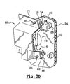
- the method comprises a fourth step, shown in FIGS. 3D and 4D, of separating the covering element 24 from the equipment module 10 by a transverse movement towards the left with respect to the equipment module 10, so that the fingers 28 are no longer received in the clamps 27.
- This transverse displacement of the covering element 24 also makes it possible to position it with respect to the structural element 12.
- the method comprises a last step, not shown, of fixing the covering element 24 on the structural element 12.
- the uncoupling step consists of a transverse movement of the cladding element 24 with respect to the equipment module 10, the distance "d" between these two elements can be as small as possible, with the only condition of do not interfere with the uncoupling movement.
- the equipment module 10 and the covering element 24 arrive simultaneously on the assembly line of the vehicle.
- the risk of out of stock is reduced.
- the fastening of the equipment module 10 and the covering element 24 is carried out independently of the vehicle mounting, which reduces the assembly time, resulting in increased productivity.
Landscapes
- Engineering & Computer Science (AREA)
- Mechanical Engineering (AREA)
- Manufacturing & Machinery (AREA)
- Chemical & Material Sciences (AREA)
- Combustion & Propulsion (AREA)
- Transportation (AREA)
- Automobile Manufacture Line, Endless Track Vehicle, Trailer (AREA)
- Body Structure For Vehicles (AREA)
Claims (12)
- Verfahren zum Zusammenbau eines Ausrüstungsmoduls (10) und eines Verkleidungselements (24) auf einem Strukturelement (12) eines Kraftfahrzeugs, von dem Typ, der eine Befestigungsstufe des Ausrüstungsmoduls (10) auf einer Seite (13) des Strukturelements (12) und eine Befestigungsstufe des Verkleidungselements (24) auf der genannte Seite (13) umfasst,
dadurch gekennzeichnet, dass es eine anfängliche Stufe zur provisorischen festen Befestigung des Ausrüstungsmoduls (10) mit dem Verkleidungselement (24) und eine Positionierungsstufe der auf diese Weise durch das Ausrüstungsmodul (10) und das Verkleidungselement (24) gebildete Struktur im Verhältnis zum Strukturelement (12) umfasst. - Verfahren gemäß dem vorherigen Anspruch, dadurch gekennzeichnet, das es eine Lösungsstufe des Ausrüstungsmoduls (10) von dem Verkleidungsmodul (24) nach der Positionierungsstufe umfasst.
- Verfahren gemäß dem vorherigen Anspruch, dadurch gekennzeichnet, dass die Lösungsstufe und die Befestigungsstufe des Ausrüstungsmoduls (10) auf dem Strukturelement (12) gleichzeitig sind.
- Verfahren gemäß dem vorherigen Anspruch, dadurch gekennzeichnet, dass die Lösungsstufe in der Verschiebung des Ausrüstungsmoduls (10) im Verhältnis zum Verkleidungselement (24) gemäß einer global senkrechten Richtung zur Seite (13) des Strukturelements (12) besteht.
- Verfahren gemäß Anspruch 1 oder 2, dadurch gekennzeichnet, dass es aufeinander folgend Folgendes umfasst:- die vorübergehende Stufe zur festen Befestigung;- die Positionierungsstufe;- die Befestigungsstufe des Ausrüstungsmoduls (10) auf dem Strukturelement (12);- die Lösungsstufe; und- die Befestigungsstufe des Verkleidungselements (24) auf dem Strukturelement (12).
- Verfahren gemäß dem vorherigen Anspruch, dadurch gekennzeichnet, dass die Lösungsstufe in der Verschiebung des Verkleidungselements (24) gegenüber dem Ausrüstungsmodul (12) gemäß einer zur Seite (13) des Strukturelements (12) deutlich parallelen Richtung besteht.
- Anordnung für die Befestigung eines Ausrüstungsmoduls (10) und eines Verkleidungselements (24) auf einer Seite (13) eines Strukturelements (12) eines Kraftfahrzeugs für die Umsetzung eines Verfahrens gemäß einem der vorherigen Ansprüche von dem Typ, in dem das Ausrüstungsmodul (10) zwischen der genannten Seite (13) des Strukturelements (12) und des Verkleidungselements (24) zwischengeschaltet ist,
dadurch gekennzeichnet, dass das Ausrüstungselement (10) und das Verkleidungselement (24) durch Mittel (26, 27, 28) verbunden sind, die eine provisorische feste Befestigung des Ausrüstungsmoduls (10) mit dem Verkleidungselement (24) vor ihrer Befestigung auf dem Strukturelement (12) erlauben. - Anordnung gemäß dem vorherigen Anspruch, dadurch gekennzeichnet, dass das Ausrüstungsmodul (10) und das Verkleidungselement (24) über durch elastisches Verrasten abnehmbare Verbindungsmittel (26, 27, 28) verbunden sind.
- Anordnung gemäß dem vorherigen Anspruch, dadurch gekennzeichnet, dass das Ausrüstungsmodul (10) und das Verkleidungsmodul (24) über wenigstens eine elastische Klemme (27) verbunden sind, die geeignet ist, sich zu öffnen, um die Lösung des Ausrüstungsmoduls (10) von dem Verkleidungselement (24) zu erlauben.
- Anordnung gemäß dem vorherigen Anspruch, dadurch gekennzeichnet, dass die Klemme (27) durch das Verkleidungselement (24) getragen wird.
- Anordnung gemäß dem vorherigen Anspruch, dadurch gekennzeichnet, dass die Klemme (27) eine Stützseite (36) eines dem Ausrüstungsmodul (10) zugeordneten Fingers (28) für die Positionierung des Ausrüstungsmoduls (10) im Verhältnis zum Verkleidungselement (24) gemäß einer zur Seite (13) des Strukturelements (12) deutlich senkrechten Richtung umfasst.
- Anordnung gemäß Anspruch 9 bis 11, dadurch gekennzeichnet, dass das Verkleidungselement (24) wenigstens drei Klemmen (27) trägt, die jeweils mit einem komplementären Finger (28) des Ausrüstungsmoduls (10) zur Positionierung des Antriebselements auf dem Verkleidungselement (24) in einer zur Ebene der Seite (13) des Strukturelements (12) parallelen Ebene zusammenwirken.
Applications Claiming Priority (2)
| Application Number | Priority Date | Filing Date | Title |
|---|---|---|---|
| FR0203861 | 2002-03-27 | ||
| FR0203861A FR2837780B1 (fr) | 2002-03-27 | 2002-03-27 | Procede d'assemblage d'un module d'equipement et d'un element d'habillage de vehicule automobile et agencement pour un tel assemblage |
Publications (2)
| Publication Number | Publication Date |
|---|---|
| EP1348614A1 EP1348614A1 (de) | 2003-10-01 |
| EP1348614B1 true EP1348614B1 (de) | 2006-05-03 |
Family
ID=27799275
Family Applications (1)
| Application Number | Title | Priority Date | Filing Date |
|---|---|---|---|
| EP03006056A Expired - Lifetime EP1348614B1 (de) | 2002-03-27 | 2003-03-19 | Montageverfahren für ein Kraftfahrzeug-Ausstattungsmodul und ein Karrosserieteil, und Anordnung für eine derartige Montage |
Country Status (4)
| Country | Link |
|---|---|
| EP (1) | EP1348614B1 (de) |
| AT (1) | ATE325027T1 (de) |
| DE (1) | DE60304921T2 (de) |
| FR (1) | FR2837780B1 (de) |
Families Citing this family (12)
| Publication number | Priority date | Publication date | Assignee | Title |
|---|---|---|---|---|
| US7246840B2 (en) | 2003-01-31 | 2007-07-24 | Valeo Electrical Systems, Inc. | Vehicle liftgate window component module |
| FR2853606B1 (fr) * | 2003-04-11 | 2006-04-21 | Valeo Systemes Dessuyage | Procede et agencement pour l'assemblage par succession de deux mouvements selon une direction longitudinale |
| US7537256B2 (en) | 2004-03-02 | 2009-05-26 | Valeo Electrical Systems, Inc. | Component module applique for vehicle lift gate |
| FR2871126B1 (fr) * | 2004-06-03 | 2007-10-05 | Valeo Systemes Dessuyage | Agencement pour la solidarisation d'un dispositif d'essuyage de vehicule automobile |
| WO2006095630A1 (ja) * | 2005-03-09 | 2006-09-14 | Mitsuba Corporation | 電動機の取付け構造 |
| DE102005050249A1 (de) * | 2005-10-20 | 2007-04-26 | Volkswagen Ag | Flexibles fügeoptimiertes Anbauteil |
| JP4981340B2 (ja) * | 2006-03-29 | 2012-07-18 | 株式会社ミツバ | 減速装置付きモータ |
| JP2007267555A (ja) * | 2006-03-29 | 2007-10-11 | Mitsuba Corp | 減速装置付きモータ |
| FR2917035B1 (fr) * | 2007-06-07 | 2010-02-26 | Peugeot Citroen Automobiles Sa | Ensemble d'extremite de vehicule automobile comprenant un absorbeur a lames elastiques. |
| FR2921040B1 (fr) * | 2007-09-14 | 2010-06-18 | Peugeot Citroen Automobiles Sa | Procede d'assemblage d'une peau de pare-chocs sur une caisse de vehicule automobile. |
| DE102007047126B4 (de) * | 2007-10-02 | 2017-09-21 | Robert Bosch Gmbh | Wischanlage, Verfahren zur Montage einer Wischanlage sowie Kraftfahrzeug |
| CN105015492A (zh) * | 2015-08-13 | 2015-11-04 | 神龙汽车有限公司 | 一种可快速安装的新型后雨刮电机总成 |
Family Cites Families (2)
| Publication number | Priority date | Publication date | Assignee | Title |
|---|---|---|---|---|
| FR2720451B1 (fr) * | 1994-05-30 | 1996-06-21 | Valeo Systemes Dessuyage | Agencement pour le montage et la fixation d'un ensemble sur la caisse d'un véhicule automobile et module d'essuyage comportant un tel agencement. |
| DE19525553A1 (de) * | 1995-07-13 | 1997-01-16 | Teves Gmbh Alfred | Scheibenwischeranlage für ein Kraftfahrzeug |
-
2002
- 2002-03-27 FR FR0203861A patent/FR2837780B1/fr not_active Expired - Fee Related
-
2003
- 2003-03-19 EP EP03006056A patent/EP1348614B1/de not_active Expired - Lifetime
- 2003-03-19 AT AT03006056T patent/ATE325027T1/de not_active IP Right Cessation
- 2003-03-19 DE DE60304921T patent/DE60304921T2/de not_active Expired - Lifetime
Also Published As
| Publication number | Publication date |
|---|---|
| DE60304921T2 (de) | 2007-06-14 |
| ATE325027T1 (de) | 2006-06-15 |
| DE60304921D1 (de) | 2006-06-08 |
| FR2837780B1 (fr) | 2004-06-25 |
| FR2837780A1 (fr) | 2003-10-03 |
| EP1348614A1 (de) | 2003-10-01 |
Similar Documents
| Publication | Publication Date | Title |
|---|---|---|
| EP1613516B1 (de) | Verfahren und vorrichtung zur montage einer wischanlage an eine fahrzeugkarosserie | |
| EP1348614A1 (de) | Montageverfahren für ein Kraftfahrzeug-Ausstattungsmodul und ein Karrosserieteil, und Anordnung für eine derartige Montage | |
| EP2969623B1 (de) | Kühleinheit mit ausgleichsmitteln für fertigungstoleranzen | |
| FR2839691A1 (fr) | Agencement pour le positionnement et la fixation des moyens d'entrainement d'un mecanisme d'essuie-glace | |
| EP1787041B1 (de) | Anordnung zur befestigung eines wischermechanismus | |
| EP0230837B1 (de) | Vorrichtung zum Senkrechtstellen, insbesondere von Windschutzscheiben | |
| WO2012117189A1 (fr) | Vehicule comportant un absorbeur de choc et absorbeur de choc correspondant | |
| EP0478403B1 (de) | Befestigungseinrichtung für einen Kühler eines Kraftfahrzeugmotors | |
| FR2975352A1 (fr) | Dispositif de positionnement relatif d'un module de retroviseur et d'un support. | |
| EP2033848B1 (de) | Zierelement für Windschutzscheibe/Windlaufgrill eines Kraftfahrzeugs | |
| WO2002057102A1 (fr) | Hayon de vehicule automobile et procede de montage de ce hayon | |
| FR3145130A1 (fr) | Pare-chocs pour véhicule automobile avec bloc d’attache de connecteurs électrique | |
| FR2496353A1 (fr) | Dispositif de montage d'un ecran pare-chaleur pour machine tournante electrique | |
| FR3140591A1 (fr) | Renfort de pare-chocs pour véhicule automobile et véhicule automobile équipé d’un tel renfort | |
| EP1801331B1 (de) | Griffstütze | |
| EP0638463B1 (de) | Dichtungsvorrichtung des Typs verwendend ein Befestigungselement auf einem Kraftfahrzeuguntergestell- oder Aufbauanlage und ein Dichtungselement | |
| EP1599376B1 (de) | Vordere fussanordnung in einem pkw | |
| FR2868371A1 (fr) | Ensemble de montage d'une barre de toit longitudinale sur un toit d'un vehicule automobile | |
| EP3361026B1 (de) | Türgriff mit befestigung durch aussenschraube | |
| EP1838568B1 (de) | Kraftfahrzeugmodul mit verbesserten zentrierungsmitteln in bezug auf die fahrzeugkarosserie und entsprechendes karosserieelement | |
| FR2784955A1 (fr) | Dispositif de fixation d'un element exterieur de carrosserie sur une structure de vehicule, et vehicule comportant un tel dispositif | |
| FR2937926A1 (fr) | Support multifonction pour vehicule automobile. | |
| FR2895323A3 (fr) | Biellette de reprise de couple | |
| EP1827906B1 (de) | Optische einheit eines fahrzeugs mit strukturellem teil und fahrzeugs-querstrebe | |
| WO2005113992A1 (fr) | Accessoire de véhicule automobile |
Legal Events
| Date | Code | Title | Description |
|---|---|---|---|
| PUAI | Public reference made under article 153(3) epc to a published international application that has entered the european phase |
Free format text: ORIGINAL CODE: 0009012 |
|
| 17P | Request for examination filed |
Effective date: 20030319 |
|
| AK | Designated contracting states |
Kind code of ref document: A1 Designated state(s): AT BE BG CH CY CZ DE DK EE ES FI FR GB GR HU IE IT LI LU MC NL PT RO SE SI SK TR |
|
| AX | Request for extension of the european patent |
Extension state: AL LT LV MK |
|
| AKX | Designation fees paid |
Designated state(s): AT BE BG CH CY CZ DE DK EE ES FI FR GB GR HU IE IT LI LU MC NL PT RO SE SI SK TR |
|
| GRAP | Despatch of communication of intention to grant a patent |
Free format text: ORIGINAL CODE: EPIDOSNIGR1 |
|
| GRAS | Grant fee paid |
Free format text: ORIGINAL CODE: EPIDOSNIGR3 |
|
| GRAA | (expected) grant |
Free format text: ORIGINAL CODE: 0009210 |
|
| AK | Designated contracting states |
Kind code of ref document: B1 Designated state(s): AT BE BG CH CY CZ DE DK EE ES FI FR GB GR HU IE IT LI LU MC NL PT RO SE SI SK TR |
|
| PG25 | Lapsed in a contracting state [announced via postgrant information from national office to epo] |
Ref country code: AT Free format text: LAPSE BECAUSE OF FAILURE TO SUBMIT A TRANSLATION OF THE DESCRIPTION OR TO PAY THE FEE WITHIN THE PRESCRIBED TIME-LIMIT Effective date: 20060503 Ref country code: IT Free format text: LAPSE BECAUSE OF FAILURE TO SUBMIT A TRANSLATION OF THE DESCRIPTION OR TO PAY THE FEE WITHIN THE PRESCRIBED TIME-LIMIT;WARNING: LAPSES OF ITALIAN PATENTS WITH EFFECTIVE DATE BEFORE 2007 MAY HAVE OCCURRED AT ANY TIME BEFORE 2007. THE CORRECT EFFECTIVE DATE MAY BE DIFFERENT FROM THE ONE RECORDED. Effective date: 20060503 Ref country code: SI Free format text: LAPSE BECAUSE OF FAILURE TO SUBMIT A TRANSLATION OF THE DESCRIPTION OR TO PAY THE FEE WITHIN THE PRESCRIBED TIME-LIMIT Effective date: 20060503 Ref country code: SK Free format text: LAPSE BECAUSE OF FAILURE TO SUBMIT A TRANSLATION OF THE DESCRIPTION OR TO PAY THE FEE WITHIN THE PRESCRIBED TIME-LIMIT Effective date: 20060503 Ref country code: CZ Free format text: LAPSE BECAUSE OF FAILURE TO SUBMIT A TRANSLATION OF THE DESCRIPTION OR TO PAY THE FEE WITHIN THE PRESCRIBED TIME-LIMIT Effective date: 20060503 Ref country code: FI Free format text: LAPSE BECAUSE OF FAILURE TO SUBMIT A TRANSLATION OF THE DESCRIPTION OR TO PAY THE FEE WITHIN THE PRESCRIBED TIME-LIMIT Effective date: 20060503 Ref country code: GB Free format text: LAPSE BECAUSE OF FAILURE TO SUBMIT A TRANSLATION OF THE DESCRIPTION OR TO PAY THE FEE WITHIN THE PRESCRIBED TIME-LIMIT Effective date: 20060503 Ref country code: IE Free format text: LAPSE BECAUSE OF FAILURE TO SUBMIT A TRANSLATION OF THE DESCRIPTION OR TO PAY THE FEE WITHIN THE PRESCRIBED TIME-LIMIT Effective date: 20060503 Ref country code: NL Free format text: LAPSE BECAUSE OF FAILURE TO SUBMIT A TRANSLATION OF THE DESCRIPTION OR TO PAY THE FEE WITHIN THE PRESCRIBED TIME-LIMIT Effective date: 20060503 Ref country code: RO Free format text: LAPSE BECAUSE OF FAILURE TO SUBMIT A TRANSLATION OF THE DESCRIPTION OR TO PAY THE FEE WITHIN THE PRESCRIBED TIME-LIMIT Effective date: 20060503 |
|
| REG | Reference to a national code |
Ref country code: GB Ref legal event code: FG4D Free format text: NOT ENGLISH |
|
| REG | Reference to a national code |
Ref country code: CH Ref legal event code: EP |
|
| REF | Corresponds to: |
Ref document number: 60304921 Country of ref document: DE Date of ref document: 20060608 Kind code of ref document: P |
|
| REG | Reference to a national code |
Ref country code: IE Ref legal event code: FG4D Free format text: LANGUAGE OF EP DOCUMENT: FRENCH |
|
| PG25 | Lapsed in a contracting state [announced via postgrant information from national office to epo] |
Ref country code: SE Free format text: LAPSE BECAUSE OF FAILURE TO SUBMIT A TRANSLATION OF THE DESCRIPTION OR TO PAY THE FEE WITHIN THE PRESCRIBED TIME-LIMIT Effective date: 20060803 Ref country code: DK Free format text: LAPSE BECAUSE OF FAILURE TO SUBMIT A TRANSLATION OF THE DESCRIPTION OR TO PAY THE FEE WITHIN THE PRESCRIBED TIME-LIMIT Effective date: 20060803 |
|
| PG25 | Lapsed in a contracting state [announced via postgrant information from national office to epo] |
Ref country code: ES Free format text: LAPSE BECAUSE OF FAILURE TO SUBMIT A TRANSLATION OF THE DESCRIPTION OR TO PAY THE FEE WITHIN THE PRESCRIBED TIME-LIMIT Effective date: 20060814 |
|
| PG25 | Lapsed in a contracting state [announced via postgrant information from national office to epo] |
Ref country code: PT Free format text: LAPSE BECAUSE OF FAILURE TO SUBMIT A TRANSLATION OF THE DESCRIPTION OR TO PAY THE FEE WITHIN THE PRESCRIBED TIME-LIMIT Effective date: 20061003 |
|
| NLV1 | Nl: lapsed or annulled due to failure to fulfill the requirements of art. 29p and 29m of the patents act | ||
| GBV | Gb: ep patent (uk) treated as always having been void in accordance with gb section 77(7)/1977 [no translation filed] |
Effective date: 20060503 |
|
| REG | Reference to a national code |
Ref country code: IE Ref legal event code: FD4D |
|
| PLBE | No opposition filed within time limit |
Free format text: ORIGINAL CODE: 0009261 |
|
| STAA | Information on the status of an ep patent application or granted ep patent |
Free format text: STATUS: NO OPPOSITION FILED WITHIN TIME LIMIT |
|
| 26N | No opposition filed |
Effective date: 20070206 |
|
| REG | Reference to a national code |
Ref country code: CH Ref legal event code: PL |
|
| BERE | Be: lapsed |
Owner name: VALEO SYSTEMES D'ESSUYAGE Effective date: 20070331 |
|
| PG25 | Lapsed in a contracting state [announced via postgrant information from national office to epo] |
Ref country code: BE Free format text: LAPSE BECAUSE OF NON-PAYMENT OF DUE FEES Effective date: 20070331 |
|
| PG25 | Lapsed in a contracting state [announced via postgrant information from national office to epo] |
Ref country code: MC Free format text: LAPSE BECAUSE OF NON-PAYMENT OF DUE FEES Effective date: 20070331 |
|
| PG25 | Lapsed in a contracting state [announced via postgrant information from national office to epo] |
Ref country code: LI Free format text: LAPSE BECAUSE OF NON-PAYMENT OF DUE FEES Effective date: 20070331 Ref country code: CH Free format text: LAPSE BECAUSE OF NON-PAYMENT OF DUE FEES Effective date: 20070331 |
|
| PG25 | Lapsed in a contracting state [announced via postgrant information from national office to epo] |
Ref country code: GR Free format text: LAPSE BECAUSE OF FAILURE TO SUBMIT A TRANSLATION OF THE DESCRIPTION OR TO PAY THE FEE WITHIN THE PRESCRIBED TIME-LIMIT Effective date: 20060804 |
|
| PG25 | Lapsed in a contracting state [announced via postgrant information from national office to epo] |
Ref country code: BG Free format text: LAPSE BECAUSE OF FAILURE TO SUBMIT A TRANSLATION OF THE DESCRIPTION OR TO PAY THE FEE WITHIN THE PRESCRIBED TIME-LIMIT Effective date: 20060803 |
|
| PG25 | Lapsed in a contracting state [announced via postgrant information from national office to epo] |
Ref country code: EE Free format text: LAPSE BECAUSE OF FAILURE TO SUBMIT A TRANSLATION OF THE DESCRIPTION OR TO PAY THE FEE WITHIN THE PRESCRIBED TIME-LIMIT Effective date: 20060503 |
|
| PG25 | Lapsed in a contracting state [announced via postgrant information from national office to epo] |
Ref country code: CY Free format text: LAPSE BECAUSE OF FAILURE TO SUBMIT A TRANSLATION OF THE DESCRIPTION OR TO PAY THE FEE WITHIN THE PRESCRIBED TIME-LIMIT Effective date: 20060503 Ref country code: LU Free format text: LAPSE BECAUSE OF NON-PAYMENT OF DUE FEES Effective date: 20070319 |
|
| PG25 | Lapsed in a contracting state [announced via postgrant information from national office to epo] |
Ref country code: HU Free format text: LAPSE BECAUSE OF FAILURE TO SUBMIT A TRANSLATION OF THE DESCRIPTION OR TO PAY THE FEE WITHIN THE PRESCRIBED TIME-LIMIT Effective date: 20061104 Ref country code: TR Free format text: LAPSE BECAUSE OF FAILURE TO SUBMIT A TRANSLATION OF THE DESCRIPTION OR TO PAY THE FEE WITHIN THE PRESCRIBED TIME-LIMIT Effective date: 20060503 |
|
| PGFP | Annual fee paid to national office [announced via postgrant information from national office to epo] |
Ref country code: DE Payment date: 20150311 Year of fee payment: 13 |
|
| REG | Reference to a national code |
Ref country code: FR Ref legal event code: PLFP Year of fee payment: 14 |
|
| REG | Reference to a national code |
Ref country code: DE Ref legal event code: R119 Ref document number: 60304921 Country of ref document: DE |
|
| PG25 | Lapsed in a contracting state [announced via postgrant information from national office to epo] |
Ref country code: DE Free format text: LAPSE BECAUSE OF NON-PAYMENT OF DUE FEES Effective date: 20161001 |
|
| REG | Reference to a national code |
Ref country code: FR Ref legal event code: PLFP Year of fee payment: 15 |
|
| REG | Reference to a national code |
Ref country code: FR Ref legal event code: PLFP Year of fee payment: 16 |
|
| PGFP | Annual fee paid to national office [announced via postgrant information from national office to epo] |
Ref country code: FR Payment date: 20200331 Year of fee payment: 18 |
|
| PG25 | Lapsed in a contracting state [announced via postgrant information from national office to epo] |
Ref country code: FR Free format text: LAPSE BECAUSE OF NON-PAYMENT OF DUE FEES Effective date: 20210331 |