EP1348785A1 - Dispositif de traitement de produits allongés, en particulier de textiles filés - Google Patents
Dispositif de traitement de produits allongés, en particulier de textiles filés Download PDFInfo
- Publication number
- EP1348785A1 EP1348785A1 EP03007035A EP03007035A EP1348785A1 EP 1348785 A1 EP1348785 A1 EP 1348785A1 EP 03007035 A EP03007035 A EP 03007035A EP 03007035 A EP03007035 A EP 03007035A EP 1348785 A1 EP1348785 A1 EP 1348785A1
- Authority
- EP
- European Patent Office
- Prior art keywords
- treatment room
- yarn
- treatment
- textile
- treating
- Prior art date
- Legal status (The legal status is an assumption and is not a legal conclusion. Google has not performed a legal analysis and makes no representation as to the accuracy of the status listed.)
- Withdrawn
Links
- 239000004753 textile Substances 0.000 title claims description 62
- 238000007789 sealing Methods 0.000 claims abstract description 63
- 239000012530 fluid Substances 0.000 claims abstract description 62
- 238000000034 method Methods 0.000 claims abstract description 47
- 230000008569 process Effects 0.000 claims abstract description 32
- 238000002156 mixing Methods 0.000 claims abstract description 13
- 238000011144 upstream manufacturing Methods 0.000 claims abstract description 4
- 239000000463 material Substances 0.000 claims description 37
- 239000007789 gas Substances 0.000 claims description 23
- 239000007788 liquid Substances 0.000 claims description 22
- 238000001816 cooling Methods 0.000 claims description 19
- 238000000926 separation method Methods 0.000 claims description 17
- 239000000126 substance Substances 0.000 claims description 14
- 230000008859 change Effects 0.000 claims description 12
- -1 polypropylene Polymers 0.000 claims description 10
- 229920006395 saturated elastomer Polymers 0.000 claims description 10
- CSCPPACGZOOCGX-UHFFFAOYSA-N Acetone Chemical compound CC(C)=O CSCPPACGZOOCGX-UHFFFAOYSA-N 0.000 claims description 6
- UHOVQNZJYSORNB-UHFFFAOYSA-N Benzene Chemical compound C1=CC=CC=C1 UHOVQNZJYSORNB-UHFFFAOYSA-N 0.000 claims description 6
- OKKJLVBELUTLKV-UHFFFAOYSA-N Methanol Chemical compound OC OKKJLVBELUTLKV-UHFFFAOYSA-N 0.000 claims description 6
- 230000033001 locomotion Effects 0.000 claims description 6
- VLKZOEOYAKHREP-UHFFFAOYSA-N n-Hexane Chemical compound CCCCCC VLKZOEOYAKHREP-UHFFFAOYSA-N 0.000 claims description 6
- 239000005445 natural material Substances 0.000 claims description 6
- 229920002994 synthetic fiber Polymers 0.000 claims description 6
- XLYOFNOQVPJJNP-UHFFFAOYSA-N water Chemical compound O XLYOFNOQVPJJNP-UHFFFAOYSA-N 0.000 claims description 6
- RTZKZFJDLAIYFH-UHFFFAOYSA-N Diethyl ether Chemical compound CCOCC RTZKZFJDLAIYFH-UHFFFAOYSA-N 0.000 claims description 5
- LFQSCWFLJHTTHZ-UHFFFAOYSA-N Ethanol Chemical compound CCO LFQSCWFLJHTTHZ-UHFFFAOYSA-N 0.000 claims description 5
- QGZKDVFQNNGYKY-UHFFFAOYSA-N Ammonia Chemical compound N QGZKDVFQNNGYKY-UHFFFAOYSA-N 0.000 claims description 4
- HEDRZPFGACZZDS-UHFFFAOYSA-N Chloroform Chemical compound ClC(Cl)Cl HEDRZPFGACZZDS-UHFFFAOYSA-N 0.000 claims description 4
- OFBQJSOFQDEBGM-UHFFFAOYSA-N Pentane Chemical compound CCCCC OFBQJSOFQDEBGM-UHFFFAOYSA-N 0.000 claims description 4
- 239000004743 Polypropylene Substances 0.000 claims description 4
- 229920002678 cellulose Polymers 0.000 claims description 4
- 239000001913 cellulose Substances 0.000 claims description 4
- LELOWRISYMNNSU-UHFFFAOYSA-N hydrogen cyanide Chemical compound N#C LELOWRISYMNNSU-UHFFFAOYSA-N 0.000 claims description 4
- BDAGIHXWWSANSR-UHFFFAOYSA-N methanoic acid Natural products OC=O BDAGIHXWWSANSR-UHFFFAOYSA-N 0.000 claims description 4
- 229920001155 polypropylene Polymers 0.000 claims description 4
- VZGDMQKNWNREIO-UHFFFAOYSA-N tetrachloromethane Chemical compound ClC(Cl)(Cl)Cl VZGDMQKNWNREIO-UHFFFAOYSA-N 0.000 claims description 4
- QTBSBXVTEAMEQO-UHFFFAOYSA-M Acetate Chemical compound CC([O-])=O QTBSBXVTEAMEQO-UHFFFAOYSA-M 0.000 claims description 3
- 239000013013 elastic material Substances 0.000 claims description 3
- 239000000835 fiber Substances 0.000 claims description 3
- 230000004044 response Effects 0.000 claims description 3
- 239000004758 synthetic textile Substances 0.000 claims description 3
- OSWFIVFLDKOXQC-UHFFFAOYSA-N 4-(3-methoxyphenyl)aniline Chemical compound COC1=CC=CC(C=2C=CC(N)=CC=2)=C1 OSWFIVFLDKOXQC-UHFFFAOYSA-N 0.000 claims description 2
- 244000198134 Agave sisalana Species 0.000 claims description 2
- 244000025254 Cannabis sativa Species 0.000 claims description 2
- 235000012766 Cannabis sativa ssp. sativa var. sativa Nutrition 0.000 claims description 2
- 235000012765 Cannabis sativa ssp. sativa var. spontanea Nutrition 0.000 claims description 2
- 240000000491 Corchorus aestuans Species 0.000 claims description 2
- 235000011777 Corchorus aestuans Nutrition 0.000 claims description 2
- 235000010862 Corchorus capsularis Nutrition 0.000 claims description 2
- 229920000742 Cotton Polymers 0.000 claims description 2
- 240000006240 Linum usitatissimum Species 0.000 claims description 2
- 235000004431 Linum usitatissimum Nutrition 0.000 claims description 2
- 229920002292 Nylon 6 Polymers 0.000 claims description 2
- 229920002302 Nylon 6,6 Polymers 0.000 claims description 2
- 239000004952 Polyamide Substances 0.000 claims description 2
- 239000004698 Polyethylene Substances 0.000 claims description 2
- 239000004793 Polystyrene Substances 0.000 claims description 2
- 239000004372 Polyvinyl alcohol Substances 0.000 claims description 2
- 229920002334 Spandex Polymers 0.000 claims description 2
- 239000004809 Teflon Substances 0.000 claims description 2
- 229920006362 Teflon® Polymers 0.000 claims description 2
- 150000001298 alcohols Chemical class 0.000 claims description 2
- 229910021529 ammonia Inorganic materials 0.000 claims description 2
- 235000009120 camo Nutrition 0.000 claims description 2
- 235000005607 chanvre indien Nutrition 0.000 claims description 2
- 235000019253 formic acid Nutrition 0.000 claims description 2
- 239000011487 hemp Substances 0.000 claims description 2
- QSHDDOUJBYECFT-UHFFFAOYSA-N mercury Chemical compound [Hg] QSHDDOUJBYECFT-UHFFFAOYSA-N 0.000 claims description 2
- 229910052753 mercury Inorganic materials 0.000 claims description 2
- 229920002647 polyamide Polymers 0.000 claims description 2
- 229920000728 polyester Polymers 0.000 claims description 2
- 229920001225 polyester resin Polymers 0.000 claims description 2
- 239000004645 polyester resin Substances 0.000 claims description 2
- 229920000573 polyethylene Polymers 0.000 claims description 2
- 229920001296 polysiloxane Polymers 0.000 claims description 2
- 229920002223 polystyrene Polymers 0.000 claims description 2
- 229920002635 polyurethane Polymers 0.000 claims description 2
- 239000004814 polyurethane Substances 0.000 claims description 2
- 229920002451 polyvinyl alcohol Polymers 0.000 claims description 2
- 235000019422 polyvinyl alcohol Nutrition 0.000 claims description 2
- BDERNNFJNOPAEC-UHFFFAOYSA-N propan-1-ol Chemical compound CCCO BDERNNFJNOPAEC-UHFFFAOYSA-N 0.000 claims description 2
- 229920002545 silicone oil Polymers 0.000 claims description 2
- 229920001169 thermoplastic Polymers 0.000 claims description 2
- 229920001187 thermosetting polymer Polymers 0.000 claims description 2
- 239000004416 thermosoftening plastic Substances 0.000 claims description 2
- ILJSQTXMGCGYMG-UHFFFAOYSA-N triacetic acid Chemical compound CC(=O)CC(=O)CC(O)=O ILJSQTXMGCGYMG-UHFFFAOYSA-N 0.000 claims description 2
- 235000013311 vegetables Nutrition 0.000 claims description 2
- 210000002268 wool Anatomy 0.000 claims description 2
- YMWUJEATGCHHMB-UHFFFAOYSA-N Dichloromethane Chemical compound ClCCl YMWUJEATGCHHMB-UHFFFAOYSA-N 0.000 claims 3
- 238000007599 discharging Methods 0.000 claims 1
- 229920002239 polyacrylonitrile Polymers 0.000 claims 1
- 239000000109 continuous material Substances 0.000 abstract 1
- 238000010438 heat treatment Methods 0.000 abstract 1
- 239000000203 mixture Substances 0.000 description 19
- 239000012528 membrane Substances 0.000 description 11
- 238000004519 manufacturing process Methods 0.000 description 6
- 230000033228 biological regulation Effects 0.000 description 5
- 230000001105 regulatory effect Effects 0.000 description 5
- 230000007704 transition Effects 0.000 description 5
- 230000003750 conditioning effect Effects 0.000 description 4
- 230000000694 effects Effects 0.000 description 4
- 238000009987 spinning Methods 0.000 description 4
- 230000008901 benefit Effects 0.000 description 3
- 230000005012 migration Effects 0.000 description 3
- 238000013508 migration Methods 0.000 description 3
- 238000003860 storage Methods 0.000 description 3
- 238000009833 condensation Methods 0.000 description 2
- 230000005494 condensation Effects 0.000 description 2
- 230000001276 controlling effect Effects 0.000 description 2
- 238000001035 drying Methods 0.000 description 2
- 230000004048 modification Effects 0.000 description 2
- 238000012986 modification Methods 0.000 description 2
- 239000003921 oil Substances 0.000 description 2
- 238000012545 processing Methods 0.000 description 2
- 230000029305 taxis Effects 0.000 description 2
- 238000012546 transfer Methods 0.000 description 2
- 238000004383 yellowing Methods 0.000 description 2
- 241001620634 Roger Species 0.000 description 1
- 239000003570 air Substances 0.000 description 1
- 238000004378 air conditioning Methods 0.000 description 1
- 239000007795 chemical reaction product Substances 0.000 description 1
- 239000003638 chemical reducing agent Substances 0.000 description 1
- 238000004140 cleaning Methods 0.000 description 1
- 230000001143 conditioned effect Effects 0.000 description 1
- 238000010276 construction Methods 0.000 description 1
- 230000001419 dependent effect Effects 0.000 description 1
- 239000006185 dispersion Substances 0.000 description 1
- 238000005516 engineering process Methods 0.000 description 1
- 230000009969 flowable effect Effects 0.000 description 1
- 238000009499 grossing Methods 0.000 description 1
- 238000010409 ironing Methods 0.000 description 1
- 125000000325 methylidene group Chemical group [H]C([H])=* 0.000 description 1
- 230000002093 peripheral effect Effects 0.000 description 1
- 230000000704 physical effect Effects 0.000 description 1
- 239000004033 plastic Substances 0.000 description 1
- 229920003023 plastic Polymers 0.000 description 1
- 230000010411 postconditioning Effects 0.000 description 1
- 239000000843 powder Substances 0.000 description 1
- 239000000047 product Substances 0.000 description 1
- 230000001737 promoting effect Effects 0.000 description 1
- 230000000630 rising effect Effects 0.000 description 1
- 239000007787 solid Substances 0.000 description 1
- 239000000243 solution Substances 0.000 description 1
- 230000006641 stabilisation Effects 0.000 description 1
- 238000011105 stabilization Methods 0.000 description 1
- 239000000725 suspension Substances 0.000 description 1
- 238000012360 testing method Methods 0.000 description 1
Images


Classifications
-
- D—TEXTILES; PAPER
- D06—TREATMENT OF TEXTILES OR THE LIKE; LAUNDERING; FLEXIBLE MATERIALS NOT OTHERWISE PROVIDED FOR
- D06B—TREATING TEXTILE MATERIALS USING LIQUIDS, GASES OR VAPOURS
- D06B3/00—Passing of textile materials through liquids, gases or vapours to effect treatment, e.g. washing, dyeing, bleaching, sizing, impregnating
- D06B3/04—Passing of textile materials through liquids, gases or vapours to effect treatment, e.g. washing, dyeing, bleaching, sizing, impregnating of yarns, threads or filaments
- D06B3/045—Passing of textile materials through liquids, gases or vapours to effect treatment, e.g. washing, dyeing, bleaching, sizing, impregnating of yarns, threads or filaments in a tube or a groove
-
- D—TEXTILES; PAPER
- D02—YARNS; MECHANICAL FINISHING OF YARNS OR ROPES; WARPING OR BEAMING
- D02J—FINISHING OR DRESSING OF FILAMENTS, YARNS, THREADS, CORDS, ROPES OR THE LIKE
- D02J13/00—Heating or cooling the yarn, thread, cord, rope, or the like, not specific to any one of the processes provided for in this subclass
- D02J13/001—Heating or cooling the yarn, thread, cord, rope, or the like, not specific to any one of the processes provided for in this subclass in a tube or vessel
Definitions
- the present invention relates to a device for Treating elongated goods, especially thread-like textile yarns made from natural materials and / or synthetic fabrics.
- Such machines are used in particular to improve the Yarn quality after spinning or twisting textile yarns used.
- the form in which the yarn is stabilized after spinning or twisting while increasing the volume of the textile yarn for example, the form in which the yarn is stabilized after spinning or twisting while increasing the volume of the textile yarn.
- Fixing devices known in which the yarn one superheated steam-air mixture in a lock or bath is exposed.
- the invention has for its object a device for Treatment of elongated goods, especially of thread-like textile yarns made from natural materials and / or to provide synthetic substances with which on cost-effective way to treat the goods to be given qualitative properties can be adjusted.
- the object is achieved by a device according to claim 1 and solved a method according to claim 13.
- a device for treating elongated good and especially of thread-like Textile yarns made from natural materials and / or synthetic materials provided which has at least one treatment room, through which the yarn is guided essentially continuously becomes.
- this treatment room the yarn becomes a treatment subject to specified process parameters.
- the treatment room at least one is connected upstream and / or downstream Sealing area through which the yarn enters the Treatment room or after leaving the treatment room is performed and which has state variables that in are essentially thermodynamic in nature at least one state variable of state variables of the Differentiate treatment room.
- elongated goods are treated, with preference thread-like textile yarns made from natural materials and / or synthetic Fabrics are treated.
- thread-like textile yarns made from natural materials and / or synthetic Fabrics are treated.
- individual textile yarns also treating a large number of textile yarns at the same time undergo in the device.
- the present invention is based on thread-like Textile yarns described, but it should be noted that other, especially elongated, goods, which do not belong to the group of thread-like textile yarns with the device and / or the method according to the present Invention can be treated.
- State variables characteristic properties of a medium especially a fluid, which essentially are thermodynamic in nature. These include, for example Understand pressure, temperature, dew point, etc. Further State variables can result from the process technology Requirements for the treatment of textile yarns.
- flowable materials such as liquids, gases, fillings, Powder, etc referred to as fluids
- their physical state is gaseous and / or liquid and / or solid and their Flow behavior essentially through fluid mechanical Properties can be described.
- the thread-like textile yarns made from individual threads or from one Variety of individual threads.
- the threads exist from at least one natural substance and / or synthetic substance, which is selected from the group of substances, which fibers, vegetable fibers, wool, polyester, polyacrylonitrite, Polyamide, polyamide-6, polyamide-66, polypropylene, cotton, Cellulose, cellulose derivatives, acetate, elastane, flax, hemp, Polyvinyl alcohol, silk, PVC, triacetate, polyacrylic acetate, Contains polyacrylic, sisal, jute and combinations thereof.
- the Treatment room at least one inlet and outlet opening through which a fluid, preferably a gas, particularly preferably also a gas-liquid mixture such as Water vapor flows.
- a fluid preferably a gas, particularly preferably also a gas-liquid mixture such as Water vapor flows.
- the inlet and outlet openings are in place with each other in gas and / or liquid connection.
- that in front of the inlet opening for the fluid in the Treatment room is a room in which the flowing fluid is heated by a heat source.
- this heat source can be a electric heater, such as one electrical resistance, a PTC element and / or a Be a heat exchanger.
- the device has a distributor for the fluid, which before the treatment room is arranged. By a given number the distributor with the treatment room is on flow paths connected.
- Distributors also have a heat source arranged around the flowing fluid according to the type described above heat in particular to overheat.
- the textile yarn in the treatment room certain treatment by predetermined process parameters is defined. These process parameters are under due to the temperature in the treatment room, Humidity, dew point and pressure determined. About the dwell time Transport speed of the textile yarn and the differential speed between the inlet and outlet of the Treatment room can be additional process parameters define.
- a different Transport speed of the transport device between one and Outlet opening of the textile yarn a predetermined differential speed of the yarn by means of which the yarn a given shrinking or stretching process in Treatment room is subjected.
- a defined shrinkage or elongation the volume or Influence and control the density of the textile yarn For example the volume of the Textile yarns, the so-called bulk, can be increased.
- Process parameters further parameters can be defined in order defines the quality and property of the treated goods to be able to influence.
- the Device a space for separating the fluid in the Treatment room and the fluid in the sealing area, through which the yarn is fed continuously.
- This room, too Called separation chamber has at least one additional opening for Discharge of gases or liquids.
- This opening can for example be a rigid opening be formed or in a preferred embodiment Valve. In a particularly preferred embodiment, the Opening a regulated valve or control loop.
- the device a control loop for controlling the position of a boundary layer two liquid media.
- This control loop is used in Separation area between the media mixing them in the to significantly reduce.
- This control loop has a flow path for Leakage fluid, a valve that the volume flow at least influenced a medium and at least partially limited flexible space with a control fluid, which Control fluid in response to physical, in particular thermodynamic conditions of the leakage fluid expands or contracted, with at least one flexible space Volume flow through the valve controls.
- a below a boundary layer is used Understanding the transition area between two media. It can be act as a spatially delimited volume within which the two media meet and at least meet mix partially.
- the boundary layer can be any Have thicknesses, but will preferably be narrowly limited.
- a flow path is understood to be a path on which a fluid is at least partially forced.
- Under a leakage fluid is a medium within the scope of the invention to understand from which preferably a predetermined amount the above boundary layer flows.
- control fluid characterizes this Invention a medium, in particular a liquid, which change their own physical properties like this can this change cause processes outside the Control fluids can be controlled.
- the media preferably have different temperatures, the first medium being particularly preferably a gas, especially air with a temperature between 5 degrees Celsius and 60 degrees Celsius, preferably between 10 degrees Celsius and 40 Degrees Celsius and particularly preferably between 10 degrees Celsius and is 20 degrees Celsius.
- the second medium is preferably a Gas, especially steam with a temperature between 80 degrees Celsius and 180 degrees Celsius, preferably between 90 degrees Celsius and 150 degrees Celsius and particularly preferably between 100 degrees Celsius and 130 degrees Celsius.
- the Control fluid a high compared to water Coefficient of thermal expansion.
- the control fluid at least one fluid from a group of Fluids containing alcohols, such as ethanol, methanol, Propanol and the like, mercury, acetone, ammonia, Benzene, formic acid, hydrogen cyanide, ethyl ether, pentane, Silicone oils, carbon tetrachloride, methylene plurite, hexane, Chloroform, any mixed forms and the like.
- a mechanical connection provided, which at least to this contributes to a change in position of the valve to effect the change in volume of the control fluid. It is preferably as a reset device for the valve Preloading device, in particular a spring, is provided.
- the one room one of the media and the second room has the other medium.
- the two rooms are special preferably at least the two rooms by a first, in essential elastic separating layer gas and / or separated liquid-tight.
- a Pressure difference between the two rooms one Change in position of the valve, in particular by means of mechanical connection.
- the mechanical connection can be formed in one part or in several parts.
- a second flow path to the valve which adjoins the first room at least in one section, being between the second flow path and the first space a flexible layer is arranged.
- the present invention understood a device which is particularly suitable for mechanical movement transfer.
- the device has Treating elongated goods at least one Transport device on, before and after the treatment room is arranged.
- this transport device before and / or after Sealing area arranged.
- the arrangement before Treatment room and after the sealing report or before Sealing area and after the treatment room are possible Variants for the arrangement of a transport device Contraption.
- the transport device also in the treatment room and / or in Sealing area may be arranged. Even the separate arrangement the transport device and the sealing device is in the Purpose of the present invention.
- this has the advantage that the amounts of fluids reduced in consumption and the requirement regarding a gentle transport or as far as possible complete sealing can be achieved better. Also the Reducing the required energy requirement represents another Advantage.
- the transport device is controlled in one particularly preferred embodiment depending on the Characteristic characteristics of the end product, such as that Volume and the production speed of pre or downstream machines and processes.
- the device has a cooling section on, which is arranged after the treatment room and according a particularly preferred embodiment with compressed air is a cooled transport route for the textile yarn.
- This cooling section has a feed-through for the textile yarn at least one further opening for introducing a liquid and / or a gas.
- this can Cooling section combined with the function of the sealing area become.
- Air, water, oils and Combinations of these can be used.
- a cooling section or a so-called conditioning section and / or arranged after the treatment room to the good before treating.
- Process conditions in the cooling sections and / or Sealing areas in at least one process parameter from the given process parameters in the treatment room differ. According to a particularly preferred Embodiment this is for example the temperature Humidity, etc.
- the transport device has at least two essentially parallel to each other, designed as sealing rollers, Rotational body on.
- this follows this rotating body to a receiving device which the Treatment room and / or the sealing area together with the Sealing rollers are essentially pressure-tight to the environment concludes.
- the Sealing rolls in at least a portion of the surface elastic material.
- Thermoplastics such as polyethylene, polypropylene, Polystyrene, etc.
- thermosets such as Polyurethane, polyester resins, silicones, Teflon etc. selected becomes.
- the present invention has a device Control device with which the process parameters in Treatment room and / or the process parameters in the sealing area the cooling section and / or the pretreatment area and / or the Transport device can be controlled.
- Process parameters according to specified quality properties such as for example the shrink, the stretch, the bulge, the Control morphology of the good.
- the invention is further enhanced by a method for treating elongated goods, especially thread-like textile yarns dissolved from natural substances or synthetic substances, which besides the essentially continuous transport of the textile yarn along a given transport route through at least a treatment room, the textile yarn in at least one of these treatment rooms with specified process parameters treated and that the state variables in the treatment room, which are essentially thermodynamic state variables, by at least one different state variable in at least one sealing area can be set.
- this is essentially done continuous transport with a transport device that before and / or after the treatment room, preferably before and / or after the sealing area.
- a gas and / or a liquid used to treat textile yarn in Treatment room uses a gas and / or a liquid.
- This can be steam, preferably saturated steam and particularly preferably overheated steam.
- gases and / or liquids for treating the textile yarn considered according to the present invention.
- liquids such as water, oils, suspensions, Dispersions and solutions for treating the yarn of the present invention.
- the Transport path of the textile yarn at least before and / or after Treatment room with a gas, preferably air, especially preferably with compressed air.
- the treatment room is filled with a compressed gas and / or a liquid spatially at least in one dimension limited, so that for example at constant Transport speeds of the textile yarn the duration of treatment is limited to the distance in the treatment room.
- a particularly preferred embodiment of the present invention has the method of treating elongated goods on a separation chamber that in the area arranged between the sealing area and the treatment room and which is due to a predetermined outflow of a part the fluids from the treatment room and the sealing area Mixing these fluids, for example in the treatment room, largely avoided.
- a predetermined outflow of a part the fluids through a separation chamber for example during use of gaseous fluids in the border area between Treatment room and sealing area in the condensate Separation chamber collected and through an opening in the separation chamber derived from the device.
- the invention also relates to the use of a Device for treating elongated goods and especially of thread-like textile yarns made from natural materials and / or synthetic substances.
- the invention is essentially an im Manufacturing process integrated device for treating elongated good has been described, but it is also in Purpose of the present invention, this device as use independent device, being for such Arrangement of additional unwinding or reeling devices or after the device for treating elongated material should be provided.
- the exemplary embodiments shown below relate to preferred embodiments of a treatment device for Textile yarn, especially for heavy textile yarn such as Carpet yarns and the like, according to the present invention.
- one or more threads preferably a thread a given route and space treated in the way that the shape in which the yarn is after spinning or twisting located, stabilized and / or fixed and increased in volume, d. H. is swapped.
- This treatment device is also used, among other things, as a fixing device designated and is according to that shown here Embodiment designed so that it is in an upstream Manufacturing stage of textile yarn production, such as. B. the Calibration, twisting, spinning, spooling and any Combinations of these can be integrated.
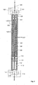
- Fig. 1 shows a treatment device according to the present Invention for textile yarns consisting essentially of two Transport devices 2, 11, two separation chambers 4, 8, one Treatment section 5 and a cooling section 9 there.
- the two transport devices 2, 11 have one Sealing sluice which, in addition to transporting the textile yarn 1, controls the tension or shrinkage of the yarn, and the Transport path of the yarn between the transport devices 2, 11 seals.
- the saturated steam flows from the distributor 7 through the bores 12 into the actual treatment room 5.
- That which forms at the boundary layer of compressed air and saturated steam Condensate is collected in the separation chamber 4, 8 and via the outlet points 25, 27 due to the prevailing Pressure in the device, driven out independently.
- the production volume can be controlled.
- a defined one Differential speed of the yarn 1 between the Transport device 2 and the transport device 11 leaves targeted influencing of predetermined property parameters the yarn too.
- the device also has a cooling section 9, which with With the help of compressed air cooling, drying and / or Conditioning of the yarn enables. Cooling the yarn allows immediate further processing in the Connection to this device and on the other hand works Ironing effect of yarn d. H. a smoothing and that associated loss of volume when leaving lock 11 opposite.
- the device has in the sealing area, the outlet openings 14, 17 and Treatment room the outlet openings 15, 16. she allow continuous flow of the corresponding Medium through the respective transport route or Transport path.
- the sealing rollers close to the lock rollers 22, 23 20, 21, which together with the receiving device 3, 10 den Transport route, in particular the sealing areas 24, 28, seal against the environment.
- the opening 26 is with the inlet opening 6 in the Fluid connection and thus enables a controlled Flow through the distributor with saturated steam, especially if the opening is equipped with a regulated valve.
- the treatment of a textile yarn in such a way that the yarn properties such. B. the bulk, the volume, the morphology specifically influenced can be.
- the relatively high pressure of the treatment medium in the Treatment room enables an even fixation over the entire cross section of the yarn.
- a so-called Yellowing of the yarn avoided.
- the immediate cooling of the Yarns following the treatment room improve the Stabilization of the yarn volume.
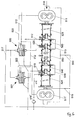
- FIG. 2 shows an alternative embodiment of the present Invention as a so-called "open" system.
- the treatment device is according to this embodiment from the transport devices 117, 116 with the transport rollers 101, 102, 114, 115. These take over the transport of the yarn 100 and control the tension via the transport speed or the shrinkage of the yarn 100.
- the device also has a room 107 in which a heat source in particular an electric heater 105 is arranged. This concludes the distributor 108 with nozzles 120 and the actual one Treatment room 109.
- the inlet 110 Saturated steam passed into room 107.
- This saturated steam flows along the heater 105 and is overheated, for example.
- This superheated steam is released into the region 104 Distributed 108 and from there via a predetermined Number of nozzles 120 passed into the treatment room.
- in the Treatment room finds the actual fixation and that Bulking the textile yarn instead.
- the specified number of nozzles and their orientation also ensures that the thread is centered in the transport path guided and tensile forces are largely avoided.
- the textile yarn in its property characteristics, especially in its Construction properties are specifically influenced.
- a yellowing is prevented by the use of cleaning steam.
- the immediate cooling of the textile yarn stabilizes the product Volume of textile yarn.
- Fig. 3 shows a detailed representation of the transport device from Fig. 1.
- the sealing rollers 200, 201 and the recording device 204 are the sealing rollers 200, 201 and the recording device 204.
- the Sealing rollers 200, 201 are, for example, by friction driven with the lock rollers 202, 203.
- the Sealing rollers 200, 201 are at least horizontally displaced, for example to pass the thread through the device or to clean the device.
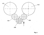
- FIG. 4 shows a sectional illustration of the sealing rollers from FIG. 3 along the line I.
- the roller bodies 300, 301 are to recognize the plastic sections 302, 303; the in her Point of contact 305 the elastic and largely tight one or Spout for the transport of the yarn in or out of the Sealing areas and / or treatment room of the device provide.
- Fig. 5 shows a transport device according to the present Invention in the open state.
- the sealing rollers 404, 405 and the receiving device 406 recognizable.
- Fig. 5 represents the Outlet of a transport device in the open state.
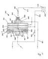
- FIG. 6 shows a further particularly preferred embodiment a treatment device, which with two according to the invention Control devices are provided around the boundary layer between the treatment room and the sealing area.
- the figure shows the treatment device with the Inlet of thread-like material 518, a first one Transport device 511, which according to a particular preferred embodiment of the present invention within the sealing area, i.e. within the Compressed air zone, in front of the treatment room located.
- a first Sealing area 528 arranged through the separation chamber 580 is separated from the treatment room 550.
- the main flow direction is the steam via line 519 a further transition area between the sealing area 524 and the separation chamber 540 also to avoid for example, condensate is heated in the guide area of the yarn and leaves this area essentially via the derivative 516, in which, for example, a condensate separator 516 is arranged.
- Leakage valves 510 and 520 are the leakage valves for the separation chambers 540 and 580 marked.
- Leakage valves are a given, preferred continuous volume flow, especially a mixture of two fluids, from the sealing area and the treatment room dissipated and as a so-called control variable for regulating the Pressure and temperature conditions in the treatment room or Sealing area supplied to the control valves 501 and 500.
- reference number 517 is the general one Compressed air supply to the device, in particular the Device for treating yarns and control valves 501 and 500 shown.
- Reference numerals 512 denote the steam supply for both the treatment device and also for the application of the control valves.
- control valve or the Control loop received.
- the mixing temperature itself is an indication of in what ratio the volumes of the two media stand when they step through the leak.
- the Mixing temperature is an indicator of the extent to which the Boundary layer in the direction of one or the other medium must have moved. The temperature or the change in this Mixing temperature is then used to determine the position of the To regulate the boundary layer.
- the device 640 is used to detect faults caused by a Migration of the boundary layer counteract. For this purpose, a media mix is carried out access 634 to device 640.
- the device is, as I said, based on the principle that the two media in the device 630 in particular also with regard to their temperature differ, since it is one medium preferably around high temperature steam, for example in Range of 120 degrees Celsius and the other medium around Compressed air at a temperature in the range of 10 to 20 degrees Celsius acts.
- the position of the boundary layer or a Change in the position of the boundary layer of both media a deviation of the mixing temperature of both media at the entrance 632 detected.
- the mixing temperature should preferably be one have a fixed value.
- the media mixture reaches a lower area 634 Room area 642 of device 640.
- This room area is 642 limited on the one hand by the housing of the device 640 and on the other hand through a wall 648. This is where it comes from Mixed media in contact with another Room area 647. More specifically, the media mix comes in Touching the wall 648, which in turn is the area 647 limited in one direction.
- the room area 647 is next to the Wall 648 also through the housing as well as one preferably at least partially elastic membrane 657 limited.
- the wall 648 is preferably not elastic and has a high Heat transfer coefficients to measure temperature changes to be transferred as quickly as possible to room area 647.
- This area 647 is preferably a liquid with a high coefficient of thermal expansion, for example Alcohol, preferably in a small amount.
- This Liquid is also referred to below as control fluid.
- This control fluid can change depending on the sign of the Extend temperature change of the medium mixture or contract. Since it is only a small amount of Control fluid acts, finds a quick response Temperature changes of the incoming media mixture take place.
- Expansion of the control fluid causes the elastic layer 657 in Fig. 3 moved to the right because that Control fluid is only in the direction of the elastic layer can expand, because it is in the other directions by im essential rigid elements is limited.
- the elastic layer 657 becomes a mechanical connection, here a plunger 641, shifted to the right in the drawing.
- This causes the total number to be marked with 649 Area a larger amount of compressed air in the chamber area 646 can occur.
- the compressed air is over to area 649 a reservoir 675 and a valve 667 are supplied.
- Of there the medium, i.e. the compressed air passes through a Line 512 and an opening in the area of Separating device, whereby the transition area in Fig. 6 after is shifted to the left because the pressure rises in the area 635.
- the reference numerals 673 and 675 refer to storage containers for the two media and that means a storage container for the vaporous medium and a storage container for the Compressed air.
- Compressed air not only enters room 646 635, but also through a junction in room 651. This creates a pressure balance between the rooms 646 and 651. Between room areas 646 and 651 an elastic layer 656 is also arranged.
- the vapor pressure or Amount of steam supplied was kept substantially constant. In this embodiment, therefore, regulation takes place via a Regulation of the compressed air instead. However, it is also possible vice versa to keep the compressed air constant and a regulation to carry out via the vapor pressure. It would also be conceivable to have one Regulation by changing both media compared to the Perform device 630.
- the medium entering area 634 is more precisely the media mixture, have a lower temperature and therefore the liquid medium 647 contracts.
- the plunger 641 to move under the Effect of a spring 643 lowers and thus the compressed air supply is reduced in the area 649.
- the spring force can preferably be variable, so that external regulation of the system is possible.
- the invention works to equal the pressures to keep, on the principle of a pressure reducer, but with the difference that the pressure of the one medium through the Pressure of the other medium is specified. So will for example the air pressure in our example through the Vapor pressure determined.
- the control loop as stated above, one filled with compressed air and the other filled with steam Room 652. As mentioned, these spaces are through the membrane or separating layer 653 separated from one another.
- the membrane is with the mechanical connection, in this case a plunger 641, connected.
- An increase in the vapor pressure or Steam temperature causes membrane 653 to deflect and the plunger 641 moves to the right.
- By lifting the Tappet can push compressed air into the system, i.e. room 646, flow.
- the plunger 641 can be made in one piece be as well as be divided into several segments, whereby preferably the plunger through the space boundaries, such as for example membrane 653 or membrane 658 becomes.
Landscapes
- Engineering & Computer Science (AREA)
- Textile Engineering (AREA)
- Treatment Of Fiber Materials (AREA)
Applications Claiming Priority (2)
| Application Number | Priority Date | Filing Date | Title |
|---|---|---|---|
| DE10214099 | 2002-03-28 | ||
| DE10214099 | 2002-03-28 |
Publications (1)
| Publication Number | Publication Date |
|---|---|
| EP1348785A1 true EP1348785A1 (fr) | 2003-10-01 |
Family
ID=27798238
Family Applications (1)
| Application Number | Title | Priority Date | Filing Date |
|---|---|---|---|
| EP03007035A Withdrawn EP1348785A1 (fr) | 2002-03-28 | 2003-03-27 | Dispositif de traitement de produits allongés, en particulier de textiles filés |
Country Status (1)
| Country | Link |
|---|---|
| EP (1) | EP1348785A1 (fr) |
Cited By (11)
| Publication number | Priority date | Publication date | Assignee | Title |
|---|---|---|---|---|
| JP2005120569A (ja) * | 2003-10-17 | 2005-05-12 | Saurer Gmbh & Co Kg | 走行する糸を蒸気状の処理媒体によって処理する装置および方法 |
| DE10348278A1 (de) * | 2003-10-17 | 2005-05-25 | Saurer Gmbh & Co. Kg | Verfahren und Vorrichtung zur Behandlung eines laufenden Fadens mit einem gas- und dampfförmigen Behandlungsmedium |
| DE102006040065A1 (de) * | 2006-08-26 | 2008-02-28 | Oerlikon Textile Gmbh & Co. Kg | Verfahren zur thermischen Behandlung eines laufenden Garns sowie Zwirnmaschine zur Durchführung des Verfahrens |
| DE102007014556A1 (de) | 2007-03-27 | 2008-10-02 | Resch Maschinenbau Gmbh | Kombination eines Verfahrens zum Erzeugen von Frieze-Garn mit einer Kablier- oder Zwirnmaschine bzw. Integration dieses Verfahrens in eine Kablier- oder Zwirnmaschine verbunden mit einer Heat-Set-Einheit |
| WO2009021851A1 (fr) * | 2007-08-14 | 2009-02-19 | Power-Heat-Set Gmbh | Récipient de thermofixation |
| EP2388363A1 (fr) | 2010-05-20 | 2011-11-23 | Oerlikon Textile GmbH & Co. KG | Ecluse à fils pour l'étanchéification d'une chambre de traitement de fil sous pression |
| EP2549002A1 (fr) | 2011-07-20 | 2013-01-23 | Oerlikon Textile GmbH & Co. KG | Chambre de traitement thermique pour fil |
| US20150152577A1 (en) * | 2013-12-03 | 2015-06-04 | Saurer Germany Gmbh & Co. Kg | Method and device for continuously processing a thread-like material |
| CN109322030A (zh) * | 2018-10-18 | 2019-02-12 | 内蒙古鹿王羊绒有限公司 | Optim纤维拉伸机的拉伸室及其使用方法 |
| CN116590825A (zh) * | 2023-05-23 | 2023-08-15 | 山东广泰机械科技有限公司 | 一种纺织原料处理系统及方法 |
| CN116607246A (zh) * | 2023-05-23 | 2023-08-18 | 山东广泰机械科技有限公司 | 一种新型纺织原料处理装置及方法 |
Citations (4)
| Publication number | Priority date | Publication date | Assignee | Title |
|---|---|---|---|---|
| GB1077525A (en) * | 1964-03-13 | 1967-08-02 | Hans Fleissner | Apparatus for the wet treatment of textiles |
| US3783649A (en) * | 1971-10-07 | 1974-01-08 | Asahi Chemical Ind | Apparatus for continuously treating fibrous materials under pressure |
| US4332151A (en) * | 1980-09-05 | 1982-06-01 | D.I.E.N.E.S Apparatebau Gmbh | Apparatus for heat treatment of synthetic yarns and fibers |
| US5287606A (en) * | 1992-03-10 | 1994-02-22 | Soft Blast, Inc. | Apparatus for treating traveling textile material in a pressurized fluid |
-
2003
- 2003-03-27 EP EP03007035A patent/EP1348785A1/fr not_active Withdrawn
Patent Citations (4)
| Publication number | Priority date | Publication date | Assignee | Title |
|---|---|---|---|---|
| GB1077525A (en) * | 1964-03-13 | 1967-08-02 | Hans Fleissner | Apparatus for the wet treatment of textiles |
| US3783649A (en) * | 1971-10-07 | 1974-01-08 | Asahi Chemical Ind | Apparatus for continuously treating fibrous materials under pressure |
| US4332151A (en) * | 1980-09-05 | 1982-06-01 | D.I.E.N.E.S Apparatebau Gmbh | Apparatus for heat treatment of synthetic yarns and fibers |
| US5287606A (en) * | 1992-03-10 | 1994-02-22 | Soft Blast, Inc. | Apparatus for treating traveling textile material in a pressurized fluid |
Cited By (21)
| Publication number | Priority date | Publication date | Assignee | Title |
|---|---|---|---|---|
| JP2005120569A (ja) * | 2003-10-17 | 2005-05-12 | Saurer Gmbh & Co Kg | 走行する糸を蒸気状の処理媒体によって処理する装置および方法 |
| DE10348278A1 (de) * | 2003-10-17 | 2005-05-25 | Saurer Gmbh & Co. Kg | Verfahren und Vorrichtung zur Behandlung eines laufenden Fadens mit einem gas- und dampfförmigen Behandlungsmedium |
| EP1528134A3 (fr) * | 2003-10-17 | 2006-01-11 | Saurer GmbH & Co. KG | Dispositif et procédé pour le traitement d'un fil en mouvement avec une vapeur |
| CN100343436C (zh) * | 2003-10-17 | 2007-10-17 | 索若两合股份有限公司 | 用蒸汽状处理物质处理运动纱线的方法和装置 |
| DE102006040065A1 (de) * | 2006-08-26 | 2008-02-28 | Oerlikon Textile Gmbh & Co. Kg | Verfahren zur thermischen Behandlung eines laufenden Garns sowie Zwirnmaschine zur Durchführung des Verfahrens |
| WO2008025411A1 (fr) * | 2006-08-26 | 2008-03-06 | Oerlikon Textile Gmbh & Co. Kg | Procédé de traitement thermique d'un fil à déroulement continu ainsi que machine de retordage pour la mise en œuvre dudit procédé |
| US7997055B2 (en) | 2006-08-26 | 2011-08-16 | Oerlikon Textile Gmbh & Co Kg | Method for the thermal treatment of a running yarn and twisting machine for carrying out the method |
| DE102007014556A1 (de) | 2007-03-27 | 2008-10-02 | Resch Maschinenbau Gmbh | Kombination eines Verfahrens zum Erzeugen von Frieze-Garn mit einer Kablier- oder Zwirnmaschine bzw. Integration dieses Verfahrens in eine Kablier- oder Zwirnmaschine verbunden mit einer Heat-Set-Einheit |
| WO2009021851A1 (fr) * | 2007-08-14 | 2009-02-19 | Power-Heat-Set Gmbh | Récipient de thermofixation |
| DE102010022211A1 (de) | 2010-05-20 | 2011-11-24 | Oerlikon Textile Gmbh & Co. Kg | Garnschleuse zur Abdichtung einer unter Überdruck stehenden Garnbehandlungskammer |
| EP2388363A1 (fr) | 2010-05-20 | 2011-11-23 | Oerlikon Textile GmbH & Co. KG | Ecluse à fils pour l'étanchéification d'une chambre de traitement de fil sous pression |
| US20110283748A1 (en) * | 2010-05-20 | 2011-11-24 | Oerlikon Textile Gmbh & Co. Kg | Yarn sluice for sealing a pressurized yarn treating chamber |
| US8893359B2 (en) * | 2010-05-20 | 2014-11-25 | Saurer Germany Gmbh & Co. Kg | Yarn sluice for sealing a pressurized yarn treating chamber |
| EP2549002A1 (fr) | 2011-07-20 | 2013-01-23 | Oerlikon Textile GmbH & Co. KG | Chambre de traitement thermique pour fil |
| DE102011108112A1 (de) | 2011-07-20 | 2013-01-24 | Oerlikon Textile Gmbh & Co. Kg | Garnbehandlungskammer |
| US9109307B2 (en) | 2011-07-20 | 2015-08-18 | Saurer Germany Gmbh & Co. Kg | Yarn treatment chamber |
| US20150152577A1 (en) * | 2013-12-03 | 2015-06-04 | Saurer Germany Gmbh & Co. Kg | Method and device for continuously processing a thread-like material |
| US9790623B2 (en) * | 2013-12-03 | 2017-10-17 | Saurer Germany Gmbh & Co. Kg | Device for continuously processing a thread-like material |
| CN109322030A (zh) * | 2018-10-18 | 2019-02-12 | 内蒙古鹿王羊绒有限公司 | Optim纤维拉伸机的拉伸室及其使用方法 |
| CN116590825A (zh) * | 2023-05-23 | 2023-08-15 | 山东广泰机械科技有限公司 | 一种纺织原料处理系统及方法 |
| CN116607246A (zh) * | 2023-05-23 | 2023-08-18 | 山东广泰机械科技有限公司 | 一种新型纺织原料处理装置及方法 |
Similar Documents
| Publication | Publication Date | Title |
|---|---|---|
| DE60309653T2 (de) | Vorrichtung zur herstellung von thermoplastischen vliesstoffen und verbundstoffen | |
| EP1348785A1 (fr) | Dispositif de traitement de produits allongés, en particulier de textiles filés | |
| DE102016219553B4 (de) | Pultrusionsverfahren, Verwendung eines Pultrusionsverfahren und Anordnung zur kontinuierlichen Herstellung von Rohlingen aus einem Faser-Kunststoff-Verbundwerkstoff | |
| WO1984002359A1 (fr) | Chambre de chauffe pour fils continus | |
| DE102016122965A1 (de) | Textilfasertrocknung | |
| EP1528134B1 (fr) | Dispositif pour le traitement d'un fil en mouvement avec une vapeur | |
| DE102008034453A1 (de) | Verfahren zum Herstellen eines Mehrschichtenverbundes auf einer CIP-fähigen Beschichtungsanlage und Verwendung des damit hergestellten Mehrschichtenverbundes für die transdermale Applikation oder die Applikation in Körperhöhlen | |
| EP1402100A1 (fr) | Procede et dispositif pour le traitement d'une masse fibreuse | |
| DE1779612B2 (de) | Vorrichtung zum kontinuierlichen Herstellen von verstärkten elastomeren Schläuchen | |
| DE102015006409A1 (de) | Vorrichtung zum Schmelzspinnen und Abkühlen einer Filamentschar | |
| EP0384886B1 (fr) | Chambre d'étirage | |
| DE10028709C2 (de) | Verfahren und Vorrichtung zur Wärmebehandlung von Fertigungsgegenständen | |
| DE2354021A1 (de) | Verfahren zum herstellen von veredeltem offenendgarn in einer spinnkammer und vorrichtung zur durchfuehrung dieses verfahrens | |
| DE2632082C2 (de) | Verfahren zur thermischen Nachbehandlung von gekräuselten thermoplastischen, multifilen Chemiefäden und Vorrichtung zum Durchführen des Verfahrens | |
| EP0468918B1 (fr) | Système de tirage à l'eau avec un effet de freinage variable | |
| CH663222A5 (de) | Spinnanlage fuer chemiefasern. | |
| DE102015016800A1 (de) | Verfahren zum Schmelzspinnen, Abziehen, Verstrecken, Relaxieren und Aufwickeln eines synthetischen Fadens für technische Anwendungszwecke und eine zugehörige Vorrichtung | |
| DE1816004A1 (de) | Verfahren und Vorrichtung zum Konditionieren von Textilstoffen | |
| DE4426336A1 (de) | Verfahren zur Behandlung einer textilen Warenbahn sowie Vorrichtung zur Durchführung desselben | |
| DE2632083A1 (de) | Kraeuselvorrichtung | |
| DE102012025076A1 (de) | Einrichtung zur Materialübergabe zwischen zwei Räumen unterschiedlicher Atmosphären und Drücke | |
| EP1101849B1 (fr) | Buse de texturation | |
| EP0324941B1 (fr) | Procédé et installation de traitement de matières textiles | |
| DE1410387A1 (de) | Verfahren und Vorrichtung zum Heissverstrecken | |
| DE10313953A1 (de) | Vorrichtung und Verfahren zur Formgebung von Textilien |
Legal Events
| Date | Code | Title | Description |
|---|---|---|---|
| PUAI | Public reference made under article 153(3) epc to a published international application that has entered the european phase |
Free format text: ORIGINAL CODE: 0009012 |
|
| AK | Designated contracting states |
Kind code of ref document: A1 Designated state(s): AT BE BG CH CY CZ DE DK EE ES FI FR GB GR HU IE IT LI LU MC NL PT RO SE SI SK TR |
|
| AX | Request for extension of the european patent |
Extension state: AL LT LV MK |
|
| AKX | Designation fees paid | ||
| REG | Reference to a national code |
Ref country code: DE Ref legal event code: 8566 |
|
| STAA | Information on the status of an ep patent application or granted ep patent |
Free format text: STATUS: THE APPLICATION IS DEEMED TO BE WITHDRAWN |
|
| 18D | Application deemed to be withdrawn |
Effective date: 20040402 |