EP1348802B1 - Verfahren und Vorrichtung zur Dispergierung eines Papierfaserstoffes - Google Patents
Verfahren und Vorrichtung zur Dispergierung eines Papierfaserstoffes Download PDFInfo
- Publication number
- EP1348802B1 EP1348802B1 EP03005093A EP03005093A EP1348802B1 EP 1348802 B1 EP1348802 B1 EP 1348802B1 EP 03005093 A EP03005093 A EP 03005093A EP 03005093 A EP03005093 A EP 03005093A EP 1348802 B1 EP1348802 B1 EP 1348802B1
- Authority
- EP
- European Patent Office
- Prior art keywords
- steam
- screw
- suspension
- conveying unit
- paper
- Prior art date
- Legal status (The legal status is an assumption and is not a legal conclusion. Google has not performed a legal analysis and makes no representation as to the accuracy of the status listed.)
- Expired - Lifetime
Links
- 239000000835 fiber Substances 0.000 title abstract description 3
- 238000000034 method Methods 0.000 title abstract 2
- 239000002002 slurry Substances 0.000 title 1
- 239000000725 suspension Substances 0.000 abstract description 15
- 238000010438 heat treatment Methods 0.000 abstract description 10
- 239000000126 substance Substances 0.000 abstract description 8
- 239000006185 dispersion Substances 0.000 abstract description 4
- 239000000654 additive Substances 0.000 abstract 1
- XLYOFNOQVPJJNP-UHFFFAOYSA-N water Substances O XLYOFNOQVPJJNP-UHFFFAOYSA-N 0.000 abstract 1
- 229920001131 Pulp (paper) Polymers 0.000 description 3
- HEMHJVSKTPXQMS-UHFFFAOYSA-M Sodium hydroxide Chemical compound [OH-].[Na+] HEMHJVSKTPXQMS-UHFFFAOYSA-M 0.000 description 3
- 230000004888 barrier function Effects 0.000 description 2
- 239000000463 material Substances 0.000 description 2
- ZAMOUSCENKQFHK-UHFFFAOYSA-N Chlorine atom Chemical compound [Cl] ZAMOUSCENKQFHK-UHFFFAOYSA-N 0.000 description 1
- CBENFWSGALASAD-UHFFFAOYSA-N Ozone Chemical compound [O-][O+]=O CBENFWSGALASAD-UHFFFAOYSA-N 0.000 description 1
- 238000004061 bleaching Methods 0.000 description 1
- 239000000460 chlorine Substances 0.000 description 1
- 229910052801 chlorine Inorganic materials 0.000 description 1
- 239000002270 dispersing agent Substances 0.000 description 1
- 239000007788 liquid Substances 0.000 description 1
- 150000002978 peroxides Chemical class 0.000 description 1
- 238000005086 pumping Methods 0.000 description 1
- 238000010792 warming Methods 0.000 description 1
Images



Classifications
-
- D—TEXTILES; PAPER
- D21—PAPER-MAKING; PRODUCTION OF CELLULOSE
- D21D—TREATMENT OF THE MATERIALS BEFORE PASSING TO THE PAPER-MAKING MACHINE
- D21D1/00—Methods of beating or refining; Beaters of the Hollander type
- D21D1/004—Methods of beating or refining including disperging or deflaking
-
- D—TEXTILES; PAPER
- D21—PAPER-MAKING; PRODUCTION OF CELLULOSE
- D21D—TREATMENT OF THE MATERIALS BEFORE PASSING TO THE PAPER-MAKING MACHINE
- D21D1/00—Methods of beating or refining; Beaters of the Hollander type
- D21D1/20—Methods of refining
-
- D—TEXTILES; PAPER
- D21—PAPER-MAKING; PRODUCTION OF CELLULOSE
- D21D—TREATMENT OF THE MATERIALS BEFORE PASSING TO THE PAPER-MAKING MACHINE
- D21D1/00—Methods of beating or refining; Beaters of the Hollander type
- D21D1/20—Methods of refining
- D21D1/30—Disc mills
-
- D—TEXTILES; PAPER
- D21—PAPER-MAKING; PRODUCTION OF CELLULOSE
- D21D—TREATMENT OF THE MATERIALS BEFORE PASSING TO THE PAPER-MAKING MACHINE
- D21D1/00—Methods of beating or refining; Beaters of the Hollander type
- D21D1/20—Methods of refining
- D21D1/34—Other mills or refiners
- D21D1/38—Other mills or refiners with horizontal shaft
-
- D—TEXTILES; PAPER
- D21—PAPER-MAKING; PRODUCTION OF CELLULOSE
- D21C—PRODUCTION OF CELLULOSE BY REMOVING NON-CELLULOSE SUBSTANCES FROM CELLULOSE-CONTAINING MATERIALS; REGENERATION OF PULPING LIQUORS; APPARATUS THEREFOR
- D21C9/00—After-treatment of cellulose pulp, e.g. of wood pulp, or cotton linters ; Treatment of dilute or dewatered pulp or process improvement taking place after obtaining the raw cellulosic material and not provided for elsewhere
- D21C9/10—Bleaching ; Apparatus therefor
Definitions
- the invention relates to a device for dispersing a paper pulp in which a pre-dewatered material is heated, conveyed and dispersed in a disperser.
- Such a device is known for example from NO 302 186 B1.
- the paper pulp is fed to a dewatering screw a heating screw, from where the heated material is introduced into the screw for a Disperger.
- the dispersion then takes place in the disperser.
- a disadvantage is in particular the high expenditure on equipment and space requirements of such a system.
- Other such devices are for example from the DE 199 54 246 A1 known.
- NO 302 186 B1 described here on the other hand, as a further possibility, the direct supply of steam between the grinding plates of Dispergers provided. The latter has the disadvantage that only a short residence time is possible and thus complete and uniform heating can not be achieved.
- the US-A-4,909,900 U.S. Patent 5,176,793 .
- EP-A-1 096 062 and WO-A-98 04774 show systems with additional heating screws, which have a high expenditure on equipment and the disadvantage of energy losses before the Disperger.
- the aim of the invention is therefore to propose a device with which a good and uniform heating can be ensured with little expenditure on equipment and, if appropriate, additional chemicals can be added before the dispersion.
- the invention is therefore characterized in that the delivery unit has at least one inlet (nozzle or inlet openings) for steam and is connected directly to the disperser. This can be heated just before the Disperger the paper pulp and eliminate an additional heating unit.
- the delivery unit is designed as a mixing screw, a uniform mixing with steam and thus a uniform heating can be achieved.
- At least one nozzle is designed as a vacuum connection, a targeted steam guide and optimum heat transfer can be achieved.
- nozzles are arranged on the housing of the pumping unit, for example a mixing screw, good heating can be achieved.
- a particularly advantageous development of the invention is characterized in that the delivery unit, for example, mixing screw has a hollow shaft, wherein the hollow shaft may have mandrels for interference.
- the steam can be targeted along the conveying path be fed, resulting in a more even distribution and thus warming.
- the inlet openings of the mandrels are provided at different radii of the delivery unit, for example a mixing screw, the introduction of steam or chemicals is equally possible even over the cross section of the conveying screw.
- Fig. 1 a plant according to the prior art
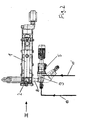
- Fig. 2 a top view of a device according to the invention
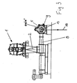
- Fig. 3 a view of Fig. 2 according to arrow III
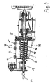
- Fig. 4 a section through a device according to the invention
- Fig. 5 a schematic representation of a variant of the invention
- Fig. 6 a special embodiment of the invention
- Fig. 7 a cut through Fig. 4 represents with a further variant of the invention.
- a plant according to the prior art in which a screw press 1 is provided for dewatering the paper fiber suspension.
- the dehydrated suspension is then supplied with a consistency of about 20-35%, advantageously 25 -30%, via a shaft 2 to a heating device 3 with rotating blades.
- the heated suspension falls into a screw 4 for feeding to the disperser 5.
- the steam is supplied to the heater 3 through a steam line 6, whereby a part can already be introduced into the shaft 2.
- the suspension to be treated is fed via an inlet port 7 of the screw press 1 and exits as plug 8 at the end.
- the plug 8 at the end of the screw press 1 serves as a vapor barrier.
- Fig. 2 shows a plan view of a device according to the invention.
- the pulp suspension to be treated is also dewatered in a screw press 1 and fed to a disperser 5 via a shaft 2 of a plug screw 8 'or subsequently a delivery unit 9, which may be designed as a feed screw.
- Fig. 3 shows a view of Fig. 2 according to arrow III.
- the screw press 1 is connected via a shaft 2 with the screw conveyor 8 '.
- the paper stock suspension is further fed to the delivery unit 9, in particular feed screw, the plug screw 8 'also serves as a vapor barrier for the supplied through line 10 steam. Behind the feed screw then the Disperger 5 is arranged.
- Fig. 4 is a section through a device according to the invention shown.
- nozzles 11 can be attached to the casing 12 at the beginning of the delivery unit or nozzles 11 'or 11 "in the end part of the delivery unit
- the delivery unit in particular the worm, is configured with a hollow shaft 13
- steam or chemicals can also be introduced in the direction 14 through the hollow shaft 13.
- mandrels 16 are provided between the worm coils 15. In this way the steam can also be easily distributed evenly over the cross section of the screw.
- a vacuum (counter to direction 14) can also be applied to the hollow shaft 13.
- steam can be introduced through the hollow shaft 13 and advantageously sucked out through the connecting piece 11. In this case can be added through the nozzle 11 'or 11 "chemicals. The suspension is then thoroughly warmed to the Disperger 5 and mixed thoroughly.
- Fig. 5 schematically shows the structure of the device according to the invention, wherein steam in the direction 14 is fed through the hollow shaft Over the length of the shaft, the steam emerges uniformly at different points.
- the pulp suspension here has a temperature of about 20 to 80 ° C, usually 40 - 60 ° C.
- the excess steam is then sucked out through the nozzles 11, 11 'or 11 "The nozzles 11, 11', 11" can also be designed as channels attached to the screw shell 12, which extend completely or partially around the circumference.
- the paper stock suspension Before entering the dispersing zone, the paper stock suspension then has a temperature greater than 85 ° C.
- Fig. 6 shows a possibility of steam supply.
- the screw shaft 15 mounted on the hollow shaft 13 is supported by a wall 18, so that a cavity 19 is formed. From the hollow shaft 13, the steam passes through openings 20 in the cavity 19 and is then passed through inlet openings 21, 21 'in the pulp suspension. Depending on the position of the inlet openings 21, 21 ', this can also be done at different points in the cross section of the delivery unit 9, in particular feed screw.
- Fig. 7 corresponds to a section along line VII-VII in FIG Fig. 4 ,
- the running within the screw shell 12 hollow shaft 13 has a plurality of mandrels 16, which may have different lengths.
- the mandrels 16 are provided with inlet openings 21, 21 ', which ensure a distribution over the cross section of the delivery unit 9.
- the spikes 16 may be open at their upper end (away from the shaft).
Landscapes
- Paper (AREA)
- Treatment Of Fiber Materials (AREA)
Description
- Die Erfindung betrifft eine Vorrichtung zur Dispergierung eines Papierfaserstoffes, bei dem ein vorentwässerter Stoff aufgeheizt, gefördert und in einem Disperger dispergiert wird.
- Eine derartige Vorrichtung ist z.B. aus der NO 302 186 B1 bekannt. Hier wird der Papierfaserstoff nach einer Entwässerungsschnecke einer Heizschnecke zugeführt, von wo der aufgeheizte Stoff in die Stopfschnecke für einen Disperger eingebracht wird. Im Disperger erfolgt dann die Dispergierung. Nachteilig ist insbesondere der hohe apparative Aufwand und auch Platzbedarf einer solchen Anlage. Weitere derartige Vorrichtungen sind z.B. aus der
DE 199 54 246 A1 bekannt. Einerseits wird hier eine Anlage analog zur NO 302 186 B1 beschrieben, andererseits ist als weitere Möglichkeit die direkte Zufuhr von Dampf zwischen die Mahlplatten des Dispergers vorgesehen. Letztere hat den Nachteil, dass nur eine kurze Verweilzeit möglich ist und dadurch keine vollständige und gleichmäßige Aufwärmung erzielt werden kann. Auch dieUS-A-4 909 900 ,US-A-5 176 793 ,EP-A-1 096 062 undWO-A-98 04774 - Ziel der Erfindung ist es daher eine Vorrichtung vorzuschlagen, mit der eine gute und gleichmäßige Aufheizung mit geringem apparativen Aufwand gewährleistet werden kann und gegebenenfalls noch zusätzlich Chemikalien vor der Dispergierung zugegeben werden können.
- Die Erfindung ist daher dadurch gekennzeichnet, dass das Förderaggregat mindestens einen Einlass (Stutzen bzw. Einlassöffnungen) für Dampf aufweist und direkt mit dem Disperger verbunden ist. Damit kann kurz vor dem Disperger der Papierfaserstoff aufgeheizt werden und ein zusätzliches Heizaggregat entfallen.
- Wenn erfindungsgemäß das Förderaggregat als Mischschnecke ausgebildet ist, kann eine gleichmäßige Durchmischung mit Dampf und damit eine gleichmäßige Aufwärmung erreicht werden.
- Wird gemäß einem weiteren Merkmal der Erfindung mindestens ein Stutzen als Vakuumanschluss ausgebildet, so kann eine gezielte Dampfführung und eine optimaler Wärmeübertragung erzielt werden.
- Werden die Stutzen am Gehäuse des Förderaggregates, beispielsweise Mischschnecke, angeordnet, so kann eine gute Aufwärmung erzielt werden.
- Eine besonders vorteilhafte Weiterbildung der Erfindung ist dadurch gekennzeichnet, dass das Förderaggregat, beispielsweise Mischschnecke eine Hohlwelle aufweist, wobei die Hohlwelle Dorne zur Einmischung aufweisen können. Damit kann der Dampf gezielt entlang des Förderweges zugeführt werden, was zu einer gleichmäßigeren Verteilung und somit Aufwärmung führt.
- Sind die Einlassöffnungen der Dorne auf unterschiedlichen Radien des Förderaggregats, beispielsweise Mischschnecke, vorgesehen, so ist die Einbringung von Dampf bzw. Chemikalien auch über den Querschnitt der Förderschnecke gleichmäßig möglich.
- Die Erfindung wird nun anhand der Zeichnungen beispielhaft beschrieben, wobei
Fig. 1 eine Anlage nach dem Stand der Technik,Fig. 2 eine Draufsicht auf eine erfindungsgemäße Vorrichtung,Fig. 3 eine Ansicht vonFig. 2 gemäß Pfeil III,Fig. 4 einen Schnitt durch eine erfindungsgemäße Vorrichtung,Fig. 5 eine schematische Darstellung einer Variante der Erfindung,Fig. 6 eine spezielle Ausgestaltung der Erfindung undFig. 7 einen Schnitt durchFig. 4 mit einer weiteren Variante der Erfindung darstellt. - In
Fig. 1 ist eine Anlage nach dem Stand der Technik dargestellt, bei der eine Schneckenpresse 1 zur Entwässerung der Papierfasersuspension vorgesehen ist. Die entwässerte Suspension wird dann mit einer Konsistenz von ca. 20 - 35 %, vorteilhaft 25 -30 %, über einen Schacht 2 einer Heizeinrichtung 3 mit rotierenden Schaufeln zugeführt. Anschließend fällt die aufgeheizte Suspension in eine Schnecke 4 zur Zuführung zum Disperger 5. Der Dampf wird der Heizeinrichtung 3 durch eine Dampfleitung 6 zugeleitet, wobei auch ein Teil bereits in den Schacht 2 eingeführt werden kann. Die zu behandelnde Suspension wird über einen Einlassstutzen 7 der Schneckenpresse 1 zugeführt und tritt als Pfropfen 8 am Ende aus. Der Pfropfen 8 am Ende der Schneckenpresse 1 dient hier als Dampfsperre. -
Fig. 2 zeigt eine Draufsicht auf eine erfindungsgemäße Vorrichtung. Hier wird ebenfalls die zu behandelnde Papierstoffsuspension in einer Schneckenpresse 1 entwässert und über einen Schacht 2 einer Stopfschnecke 8' bzw. in weiterer Folge einem Förderaggregat 9, das als Zuführschnecke ausgeführt sein kann, einem Disperger 5 zugeführt. - Weiters sind hier Leitungen 10, 10' erkennbar, über die der Papierstoffsuspension Dampf bzw. Chemikalien zugeführt werden können. Als Chemikalien kommen sowohl flüssige oder gasförmige Bleich- als auch Hygienechemikalien wie z.B. Peroxid, Natronlauge, Chlor, Ozon oder Dispergiermittel in Frage.
-
Fig. 3 zeigt eine Ansicht vonFig. 2 gemäß Pfeil III. Die Schneckenpresse 1 ist über einen Schacht 2 mit der Stopfschnecke 8' verbunden. Die Papierstoffsuspension wird weiters dem Förderaggregat 9, insbesondere Zuführschnecke zugeleitet, wobei die Stopfschnecke 8' auch als Dampfsperre für den durch Leitung 10 zugeführten Dampf dient. Hinter der Zuführschnecke ist dann der Disperger 5 angeordnet. - In
Fig. 4 ist ein Schnitt durch eine Vorrichtung gemäß der Erfindung dargestellt. Man erkennt die Einmündung der Stopfschnecke 8' und einen Zuführteil des Förderaggregats 9. Zur Dampfzufuhr können Stutzen 11 am Mantel 12 am Beginn des Förderaggregats oder Stutzen 11' oder 11" im Endteil des Förderaggregats angebracht sein. Durch diese Stutzen können auch alternativ Chemikalien zugeführt werden. Wird das Förderaggregat, insbesondere Schnecke, mit einer Hohlwelle 13 ausgestaltet, so kann auch Dampf bzw. Chemikalien in Richtung 14 durch die Hohlwelle 13 eingebracht werden. Besonders vorteilhaft ist es, wenn zwischen den Schneckenwendeln 15 Dorne 16 vorgesehen sind. Auf diese Weise kann der Dampf auch einfach über den Querschnitt der Schnecke gleichmäßig verteilt eingebracht werden. - Wird der Dampf über die Stutzen 11, 11' oder 11" eingebracht, kann auch an die Hohlwelle 13 ein Vakuum (entgegen Richtung 14) angelegt werden. Alternativ kann durch die Hohlwelle 13 Dampf eingebracht und vorteilhafterweise durch Stutzen 11 abgesaugt werden. In diesem Fall können durch die Stutzen 11' bzw. 11" Chemikalien zugegeben werden. Anschließend wird die Suspension dem Disperger 5 gut durchwärmt und durchmischt zugeführt.
-
Fig. 5 zeigt schematisch den Aufbau der erfindungsgemäßen Vorrichtung, wobei Dampf in Richtung 14 durch die Hohlwelle 13 zugeführt wird. Über die Länge der Welle tritt der Dampf an verschiedenen Stellen gleichmäßig aus. Die Papierstoffsuspension hat hier eine Temperatur von ca. 20 bis zu 80 °C, meist 40 - 60 °C. Der überschüssige Dampf wird dann durch die Stutzen 11, 11' bzw. 11" abgesaugt. Die Stutzen 11, 11', 11" können auch als am Schneckenmantel 12 angebrachte, ganz oder teilweise um den Umfang reichende, Kanäle ausgeführt sein. Vor dem Eintritt in die Dispergierzone weist die Papierstoffsuspension dann eine Temperatur größer 85 °C auf. -
Fig. 6 zeigt eine Möglichkeit der Dampfzufuhr. Die auf der Hohlwelle 13 angebrachte Schneckenwendel 15 wird durch eine Wand 18 gestützt, so dass sich ein Hohlraum 19 bildet. Aus der Hohlwelle 13 tritt der Dampf durch Öffnungen 20 in den Hohlraum 19 und wird dann durch Einlassöffnungen 21, 21' in die Papierstoffsuspension geführt. Je nach Lage der Einlassöffnungen 21, 21' kann dies auch an verschiedenen Stellen des Querschnittes des Förderaggregats 9, insbesondere Zuführschnecke, erfolgen. -
Fig. 7 entspricht einem Schnitt entlang Linie VII-VII inFig. 4 . Die innerhalb des Schneckenmantels 12 laufende Hohlwelle 13 weist mehrere Dorne 16 auf, die unterschiedliche Längen haben können. Zur Dampfzufuhr in die Suspension sind die Dorne 16 mit Einlassöffnungen 21, 21' versehen, die eine Verteilung über den Querschnitt des Förderaggregats 9 gewährleisten. Auch können die Dorne 16 an ihrem oberen (von der Welle entfernten) Ende offen sein.
Claims (7)
- Vorrichtung zur Dispergierung eines Papierfaserstoffes, mit einer Zufuhreinrichtung für Dampf, einem Förderaggregat und einem Disperger, dadurch gekennzeichnet, dass das Förderaggregat (9) eine Zuführschnecke ist und dass das Förderaggregat mindestens einen Einlass (Stutzen 11, 11', 11" bzw. Einlassöffnungen 21, 21') für Dampf aufweist und direkt mit dem Disperger verbunden ist.
- Vorrichtung nach Anspruch 1, dadurch gekennzeichnet, dass das Förderaggregat (9) als Mischschnecke ausgebildet ist.
- Vorrichtung nach Anspruch 1 oder 2, dadurch gekennzeichnet, dass mindestens ein Stutzen (11, 11', 11") als Vakuumanschluss ausgebildet ist.
- Vorrichtung nach einem der Ansprüche 1 bis 3, dadurch gekennzeichnet, dass die Stutzen (11, 11', 11") am Gehäuse (12) des Förderaggregates (9), beispielsweise Mischschnecke, angeordnet sind.
- Vorrichtung nach einem der Ansprüche 1 bis 4, dadurch gekennzeichnet, dass das Förderaggregat (9), beispielsweise Mischschnecke, eine Hohlwelle (13) aufweist.
- Vorrichtung nach Anspruch 5, dadurch gekennzeichnet, dass die Hohlwelle (13) Dorne (16) zur Einmischung aufweist.
- Vorrichtung nach Anspruch 5 oder 6, dadurch gekennzeichnet, dass die Einlassöffnungen (21, 21') auf unterschiedlichen Radien des Förderaggregats (9), beispielsweise Mischschnecke, vorgesehen sind.
Priority Applications (1)
| Application Number | Priority Date | Filing Date | Title |
|---|---|---|---|
| AT03005093T ATE408041T1 (de) | 2002-03-27 | 2003-03-07 | Verfahren und vorrichtung zur dispergierung eines papierfaserstoffes |
Applications Claiming Priority (2)
| Application Number | Priority Date | Filing Date | Title |
|---|---|---|---|
| AT4802002 | 2002-03-27 | ||
| AT0048002A AT411604B (de) | 2002-03-27 | 2002-03-27 | Verfahren und vorrichtung zur dispergierung eines papierfaserstoffes |
Publications (2)
| Publication Number | Publication Date |
|---|---|
| EP1348802A1 EP1348802A1 (de) | 2003-10-01 |
| EP1348802B1 true EP1348802B1 (de) | 2008-09-10 |
Family
ID=3674924
Family Applications (1)
| Application Number | Title | Priority Date | Filing Date |
|---|---|---|---|
| EP03005093A Expired - Lifetime EP1348802B1 (de) | 2002-03-27 | 2003-03-07 | Verfahren und Vorrichtung zur Dispergierung eines Papierfaserstoffes |
Country Status (8)
| Country | Link |
|---|---|
| US (1) | US20060108083A1 (de) |
| EP (1) | EP1348802B1 (de) |
| CN (1) | CN1306113C (de) |
| AT (2) | AT411604B (de) |
| CA (1) | CA2421407A1 (de) |
| DE (1) | DE50310459D1 (de) |
| MX (1) | MXPA03002619A (de) |
| NO (1) | NO330431B1 (de) |
Families Citing this family (6)
| Publication number | Priority date | Publication date | Assignee | Title |
|---|---|---|---|---|
| AT507837B1 (de) * | 2008-12-29 | 2010-10-15 | Andritz Ag Maschf | Verfahren und vorrichtung zur entwässerung und dispergierung eines faserstoffes |
| CN106381738A (zh) * | 2016-09-28 | 2017-02-08 | 广西大学 | 一种废纸铝塑包装盒快速分离的方法 |
| CN109173963A (zh) * | 2018-09-30 | 2019-01-11 | 山东世纪阳光纸业集团有限公司 | 一种生物反应横管 |
| SE542682C2 (en) | 2018-10-31 | 2020-06-23 | Valmet Oy | A discharge screw arrangement for discharging lignocellulosic material from a lignocellulosic treatment reactor |
| DE102018127914A1 (de) * | 2018-11-08 | 2020-05-14 | Voith Patent Gmbh | Rotor für ein Heizaggregat |
| SE1950436A1 (en) * | 2019-04-08 | 2020-10-06 | Valmet Oy | Reactor assembly and method for treatment of biomass material |
Family Cites Families (15)
| Publication number | Priority date | Publication date | Assignee | Title |
|---|---|---|---|---|
| US2396587A (en) * | 1941-03-20 | 1946-03-12 | American Defibrator | Apparatus for producing pulp |
| SE436287B (sv) * | 1983-04-12 | 1984-11-26 | Sunds Defibrator | Sett och anordning for framstellning av fibermassa fran lignocellulosahaltigt material |
| DE3610940A1 (de) * | 1986-03-04 | 1987-09-10 | Escher Wyss Gmbh | Hochtemperatur-hochkonsistenz-schnellbleiche |
| NO162525C (no) * | 1986-03-18 | 1990-01-10 | Thune Eureka As | Anordning ved skiveraffinoer. |
| DE3728890C1 (de) * | 1987-08-29 | 1988-07-14 | Escher Wyss Gmbh | Verfahren zur Regelung der spezifischen Dispergierarbeit |
| SE461919B (sv) * | 1988-08-30 | 1990-04-09 | Cellwood Machinery Ab | Saett vid behandling av traefibermassa, saerskilt innehaallande returpapper, samt disperger foer genomfoerande av foerfarandet |
| US5501768A (en) * | 1992-04-17 | 1996-03-26 | Kimberly-Clark Corporation | Method of treating papermaking fibers for making tissue |
| NO180241C (no) * | 1994-12-14 | 1997-03-12 | Kvaerner Hymac As | Innretning for behandling av partikkelmasse |
| DE19614947B4 (de) * | 1996-04-16 | 2004-04-08 | Voith Paper Fiber Systems Gmbh & Co. Kg | Verfahren zur Erhöhung des Weißgrades von Papierfaserstoff |
| SE506803C2 (sv) * | 1996-07-25 | 1998-02-16 | Cellwood Machinery Ab | Sätt och anläggning för blekning av returpappersmassa |
| EP1096062B1 (de) * | 1999-10-29 | 2004-02-11 | Voith Paper Patent GmbH | Verfahren zur Erhöhung der Homogenität und des Weissgrades von Papierfaserstoff |
| US6267847B1 (en) * | 1999-11-15 | 2001-07-31 | Voith Sulzer Paper Technology North America, Inc. | Pulper for a stock preparation system |
| DE10018262A1 (de) * | 2000-04-13 | 2001-10-18 | Voith Paper Patent Gmbh | Verfahren zur Dispergierung eines Papierfaserstoffes sowie Anlage zur Durchführung des Verfahrens |
| DE10102449C1 (de) * | 2001-01-19 | 2002-03-21 | Voith Paper Patent Gmbh | Vorrichtung zur Heiß-Dispergierung eines Papierfaserstoffes |
| DE10107448A1 (de) * | 2001-02-16 | 2002-08-22 | Voith Paper Patent Gmbh | Verfahren und Vorrichtung zum Beladen von in einer Faserstoffsuspension enthaltenen Fasern mit einem Füllstoff |
-
2002
- 2002-03-27 AT AT0048002A patent/AT411604B/de not_active IP Right Cessation
-
2003
- 2003-03-07 AT AT03005093T patent/ATE408041T1/de not_active IP Right Cessation
- 2003-03-07 EP EP03005093A patent/EP1348802B1/de not_active Expired - Lifetime
- 2003-03-07 DE DE50310459T patent/DE50310459D1/de not_active Expired - Lifetime
- 2003-03-10 CA CA002421407A patent/CA2421407A1/en not_active Abandoned
- 2003-03-17 NO NO20031223A patent/NO330431B1/no not_active IP Right Cessation
- 2003-03-26 CN CNB031085415A patent/CN1306113C/zh not_active Expired - Lifetime
- 2003-03-26 MX MXPA03002619A patent/MXPA03002619A/es active IP Right Grant
- 2003-03-27 US US10/400,612 patent/US20060108083A1/en not_active Abandoned
Also Published As
| Publication number | Publication date |
|---|---|
| EP1348802A1 (de) | 2003-10-01 |
| NO20031223D0 (no) | 2003-03-17 |
| AT411604B (de) | 2004-03-25 |
| US20060108083A1 (en) | 2006-05-25 |
| DE50310459D1 (de) | 2008-10-23 |
| ATE408041T1 (de) | 2008-09-15 |
| MXPA03002619A (es) | 2004-02-12 |
| CA2421407A1 (en) | 2003-09-27 |
| CN1446976A (zh) | 2003-10-08 |
| NO20031223L (no) | 2003-09-29 |
| CN1306113C (zh) | 2007-03-21 |
| NO330431B1 (no) | 2011-04-11 |
| ATA4802002A (de) | 2003-08-15 |
Similar Documents
| Publication | Publication Date | Title |
|---|---|---|
| DE60214861T2 (de) | Verfahren zum beladen einer faserstoffsuspension mit kalziumkarbonat | |
| DE2633041C2 (de) | Vorrichtung zum Zerfasern von pflanzlichen Rohstoffen | |
| DE602004001013T2 (de) | Vorrichtung zum Öffnen und Mischen von Fasern | |
| DE68918594T2 (de) | Behandlungsverfahren und dispergiervorrichtung zum disintegrieren von holzpulpe, insbesondere von pulpe, die papierabfall enthält. | |
| DE2612827A1 (de) | Schneckenmaschine zur kontinuierlichen aufbereitung und entgasung von elastomeren und polymeren mit einer viskositaet ueber 1000 poise | |
| DE4493391C1 (de) | Mischer, insbesondere Hochleistungsmischer zur Verfeinerung von vorzerkleinerten Faserstoffen | |
| DE2818369A1 (de) | Verfahren und vorrichtung zum behandeln von feinverteiltem schuettgut, insbesondere pulpe | |
| DE2214571B2 (de) | Vorrichtung zum Tränken und Überziehen von fadenförmigem Material mit einem fließfähigen polymeren Harz | |
| DE19712653A1 (de) | Verfahren und Vorrichtung zur Dispergierung eines Papierfaserstoffes | |
| EP1147805B1 (de) | Verfahren zur Dispergierung eines Papierfaserstoffes sowie Anlage zur Durchführung des Verfahrens | |
| AT411604B (de) | Verfahren und vorrichtung zur dispergierung eines papierfaserstoffes | |
| DE2238532B2 (de) | Maschine zum behandeln von sojabohnen und aehnlichen erzeugnissen | |
| DE1034968B (de) | Kontinuierliches Verfahren zum chemischen Aufschluss von zellulosehaltigen Faserstoffen zu Zellstoff oder Halbzellstoff und Vorrichtung zu dessen Durchfuehrung | |
| AT505449A1 (de) | Dünnschichtbehandlungsapparat | |
| EP0858880A2 (de) | Vorrichtung zur Entwässerung und Zerfaserung von lignozellulosem Material | |
| DE10102449C1 (de) | Vorrichtung zur Heiß-Dispergierung eines Papierfaserstoffes | |
| AT505450B1 (de) | Dünnschichtbehandlungsapparat | |
| EP1347092B1 (de) | Verfahren und Vorrichtung zum Einmischen von Fluiden in fliessfähige Medien | |
| AT505461A1 (de) | Dünnschichtbehandlungsapparat | |
| DE1944897B2 (de) | Verfahren und Vorrichtung zum kontinuierlichen Herstellen eines nachreaktionsfähigen Pulvers | |
| EP0867561A1 (de) | Verfahren und Vorrichtungen zur Herstellung eines heissen, überwiegend Papierfasern enthaltenden Krümelstoffes | |
| EP0778370B1 (de) | Verfahren zur Zugabe von reduzierendem Bleichmittel zu einem hochkonsistenten Papierfaserstoff | |
| DE10219844C1 (de) | Verfahren zur Heissdispergierung eines Papierfaserstoffes | |
| CH649330A5 (en) | Process for increasing the specific volume in the reprocessing of waste paper pulp | |
| EP1359250B1 (de) | Verfahren zur Dispergierung eines Papierfaserstoffes |
Legal Events
| Date | Code | Title | Description |
|---|---|---|---|
| PUAI | Public reference made under article 153(3) epc to a published international application that has entered the european phase |
Free format text: ORIGINAL CODE: 0009012 |
|
| AK | Designated contracting states |
Kind code of ref document: A1 Designated state(s): AT BE BG CH CY CZ DE DK EE ES FI FR GB GR HU IE IT LI LU MC NL PT RO SE SI SK TR |
|
| AX | Request for extension of the european patent |
Extension state: AL LT LV MK |
|
| 17P | Request for examination filed |
Effective date: 20040113 |
|
| AKX | Designation fees paid |
Designated state(s): AT BE BG CH CY CZ DE DK EE ES FI FR GB GR HU IE IT LI LU MC NL PT RO SE SI SK TR |
|
| 17Q | First examination report despatched |
Effective date: 20040817 |
|
| GRAP | Despatch of communication of intention to grant a patent |
Free format text: ORIGINAL CODE: EPIDOSNIGR1 |
|
| GRAS | Grant fee paid |
Free format text: ORIGINAL CODE: EPIDOSNIGR3 |
|
| GRAA | (expected) grant |
Free format text: ORIGINAL CODE: 0009210 |
|
| AK | Designated contracting states |
Kind code of ref document: B1 Designated state(s): AT BE BG CH CY CZ DE DK EE ES FI FR GB GR HU IE IT LI LU MC NL PT RO SE SI SK TR |
|
| REG | Reference to a national code |
Ref country code: GB Ref legal event code: FG4D Free format text: NOT ENGLISH |
|
| REG | Reference to a national code |
Ref country code: CH Ref legal event code: EP |
|
| REG | Reference to a national code |
Ref country code: IE Ref legal event code: FG4D Free format text: LANGUAGE OF EP DOCUMENT: GERMAN |
|
| REF | Corresponds to: |
Ref document number: 50310459 Country of ref document: DE Date of ref document: 20081023 Kind code of ref document: P |
|
| REG | Reference to a national code |
Ref country code: SE Ref legal event code: TRGR |
|
| PG25 | Lapsed in a contracting state [announced via postgrant information from national office to epo] |
Ref country code: SI Free format text: LAPSE BECAUSE OF FAILURE TO SUBMIT A TRANSLATION OF THE DESCRIPTION OR TO PAY THE FEE WITHIN THE PRESCRIBED TIME-LIMIT Effective date: 20080910 |
|
| NLV1 | Nl: lapsed or annulled due to failure to fulfill the requirements of art. 29p and 29m of the patents act | ||
| REG | Reference to a national code |
Ref country code: IE Ref legal event code: FD4D |
|
| PG25 | Lapsed in a contracting state [announced via postgrant information from national office to epo] |
Ref country code: IE Free format text: LAPSE BECAUSE OF FAILURE TO SUBMIT A TRANSLATION OF THE DESCRIPTION OR TO PAY THE FEE WITHIN THE PRESCRIBED TIME-LIMIT Effective date: 20080910 Ref country code: ES Free format text: LAPSE BECAUSE OF FAILURE TO SUBMIT A TRANSLATION OF THE DESCRIPTION OR TO PAY THE FEE WITHIN THE PRESCRIBED TIME-LIMIT Effective date: 20081221 Ref country code: BG Free format text: LAPSE BECAUSE OF FAILURE TO SUBMIT A TRANSLATION OF THE DESCRIPTION OR TO PAY THE FEE WITHIN THE PRESCRIBED TIME-LIMIT Effective date: 20081210 |
|
| PG25 | Lapsed in a contracting state [announced via postgrant information from national office to epo] |
Ref country code: SK Free format text: LAPSE BECAUSE OF FAILURE TO SUBMIT A TRANSLATION OF THE DESCRIPTION OR TO PAY THE FEE WITHIN THE PRESCRIBED TIME-LIMIT Effective date: 20080910 Ref country code: PT Free format text: LAPSE BECAUSE OF FAILURE TO SUBMIT A TRANSLATION OF THE DESCRIPTION OR TO PAY THE FEE WITHIN THE PRESCRIBED TIME-LIMIT Effective date: 20090210 Ref country code: RO Free format text: LAPSE BECAUSE OF FAILURE TO SUBMIT A TRANSLATION OF THE DESCRIPTION OR TO PAY THE FEE WITHIN THE PRESCRIBED TIME-LIMIT Effective date: 20080910 Ref country code: NL Free format text: LAPSE BECAUSE OF FAILURE TO SUBMIT A TRANSLATION OF THE DESCRIPTION OR TO PAY THE FEE WITHIN THE PRESCRIBED TIME-LIMIT Effective date: 20080910 Ref country code: CZ Free format text: LAPSE BECAUSE OF FAILURE TO SUBMIT A TRANSLATION OF THE DESCRIPTION OR TO PAY THE FEE WITHIN THE PRESCRIBED TIME-LIMIT Effective date: 20080910 |
|
| PLBE | No opposition filed within time limit |
Free format text: ORIGINAL CODE: 0009261 |
|
| STAA | Information on the status of an ep patent application or granted ep patent |
Free format text: STATUS: NO OPPOSITION FILED WITHIN TIME LIMIT |
|
| PG25 | Lapsed in a contracting state [announced via postgrant information from national office to epo] |
Ref country code: DK Free format text: LAPSE BECAUSE OF FAILURE TO SUBMIT A TRANSLATION OF THE DESCRIPTION OR TO PAY THE FEE WITHIN THE PRESCRIBED TIME-LIMIT Effective date: 20080910 Ref country code: EE Free format text: LAPSE BECAUSE OF FAILURE TO SUBMIT A TRANSLATION OF THE DESCRIPTION OR TO PAY THE FEE WITHIN THE PRESCRIBED TIME-LIMIT Effective date: 20080910 |
|
| 26N | No opposition filed |
Effective date: 20090611 |
|
| PG25 | Lapsed in a contracting state [announced via postgrant information from national office to epo] |
Ref country code: IT Free format text: LAPSE BECAUSE OF FAILURE TO SUBMIT A TRANSLATION OF THE DESCRIPTION OR TO PAY THE FEE WITHIN THE PRESCRIBED TIME-LIMIT Effective date: 20080910 |
|
| BERE | Be: lapsed |
Owner name: ANDRITZ AG Effective date: 20090331 |
|
| PG25 | Lapsed in a contracting state [announced via postgrant information from national office to epo] |
Ref country code: MC Free format text: LAPSE BECAUSE OF NON-PAYMENT OF DUE FEES Effective date: 20090331 |
|
| REG | Reference to a national code |
Ref country code: CH Ref legal event code: PL |
|
| GBPC | Gb: european patent ceased through non-payment of renewal fee |
Effective date: 20090307 |
|
| REG | Reference to a national code |
Ref country code: FR Ref legal event code: ST Effective date: 20091130 |
|
| PG25 | Lapsed in a contracting state [announced via postgrant information from national office to epo] |
Ref country code: LI Free format text: LAPSE BECAUSE OF NON-PAYMENT OF DUE FEES Effective date: 20090331 Ref country code: CH Free format text: LAPSE BECAUSE OF NON-PAYMENT OF DUE FEES Effective date: 20090331 |
|
| PG25 | Lapsed in a contracting state [announced via postgrant information from national office to epo] |
Ref country code: BE Free format text: LAPSE BECAUSE OF NON-PAYMENT OF DUE FEES Effective date: 20090331 |
|
| PG25 | Lapsed in a contracting state [announced via postgrant information from national office to epo] |
Ref country code: FR Free format text: LAPSE BECAUSE OF NON-PAYMENT OF DUE FEES Effective date: 20091123 Ref country code: GB Free format text: LAPSE BECAUSE OF NON-PAYMENT OF DUE FEES Effective date: 20090307 |
|
| PG25 | Lapsed in a contracting state [announced via postgrant information from national office to epo] |
Ref country code: AT Free format text: LAPSE BECAUSE OF NON-PAYMENT OF DUE FEES Effective date: 20090307 |
|
| PG25 | Lapsed in a contracting state [announced via postgrant information from national office to epo] |
Ref country code: GR Free format text: LAPSE BECAUSE OF FAILURE TO SUBMIT A TRANSLATION OF THE DESCRIPTION OR TO PAY THE FEE WITHIN THE PRESCRIBED TIME-LIMIT Effective date: 20081211 |
|
| PG25 | Lapsed in a contracting state [announced via postgrant information from national office to epo] |
Ref country code: LU Free format text: LAPSE BECAUSE OF NON-PAYMENT OF DUE FEES Effective date: 20090307 |
|
| PG25 | Lapsed in a contracting state [announced via postgrant information from national office to epo] |
Ref country code: HU Free format text: LAPSE BECAUSE OF FAILURE TO SUBMIT A TRANSLATION OF THE DESCRIPTION OR TO PAY THE FEE WITHIN THE PRESCRIBED TIME-LIMIT Effective date: 20090311 |
|
| PG25 | Lapsed in a contracting state [announced via postgrant information from national office to epo] |
Ref country code: TR Free format text: LAPSE BECAUSE OF FAILURE TO SUBMIT A TRANSLATION OF THE DESCRIPTION OR TO PAY THE FEE WITHIN THE PRESCRIBED TIME-LIMIT Effective date: 20080910 |
|
| PG25 | Lapsed in a contracting state [announced via postgrant information from national office to epo] |
Ref country code: CY Free format text: LAPSE BECAUSE OF FAILURE TO SUBMIT A TRANSLATION OF THE DESCRIPTION OR TO PAY THE FEE WITHIN THE PRESCRIBED TIME-LIMIT Effective date: 20080910 |
|
| PGFP | Annual fee paid to national office [announced via postgrant information from national office to epo] |
Ref country code: FI Payment date: 20220322 Year of fee payment: 20 Ref country code: DE Payment date: 20220322 Year of fee payment: 20 |
|
| PGFP | Annual fee paid to national office [announced via postgrant information from national office to epo] |
Ref country code: SE Payment date: 20220321 Year of fee payment: 20 |
|
| REG | Reference to a national code |
Ref country code: DE Ref legal event code: R071 Ref document number: 50310459 Country of ref document: DE |
|
| REG | Reference to a national code |
Ref country code: SE Ref legal event code: EUG |