EP1348814A2 - Dispositif de verrouillage pour une flèche - Google Patents
Dispositif de verrouillage pour une flèche Download PDFInfo
- Publication number
- EP1348814A2 EP1348814A2 EP03006322A EP03006322A EP1348814A2 EP 1348814 A2 EP1348814 A2 EP 1348814A2 EP 03006322 A EP03006322 A EP 03006322A EP 03006322 A EP03006322 A EP 03006322A EP 1348814 A2 EP1348814 A2 EP 1348814A2
- Authority
- EP
- European Patent Office
- Prior art keywords
- boom
- actuator
- locking device
- swing frame
- hook assembly
- Prior art date
- Legal status (The legal status is an assumption and is not a legal conclusion. Google has not performed a legal analysis and makes no representation as to the accuracy of the status listed.)
- Granted
Links
Images


Classifications
-
- E—FIXED CONSTRUCTIONS
- E02—HYDRAULIC ENGINEERING; FOUNDATIONS; SOIL SHIFTING
- E02F—DREDGING; SOIL-SHIFTING
- E02F3/00—Dredgers; Soil-shifting machines
- E02F3/04—Dredgers; Soil-shifting machines mechanically-driven
- E02F3/28—Dredgers; Soil-shifting machines mechanically-driven with digging tools mounted on a dipper- or bucket-arm, i.e. there is either one arm or a pair of arms, e.g. dippers, buckets
- E02F3/36—Component parts
- E02F3/38—Cantilever beams, i.e. booms;, e.g. manufacturing processes, forms, geometry or materials used for booms; Dipper-arms, e.g. manufacturing processes, forms, geometry or materials used for dipper-arms; Bucket-arms
- E02F3/388—Mechanical locking means for booms or arms against rotation, e.g. during transport of the machine
-
- E—FIXED CONSTRUCTIONS
- E02—HYDRAULIC ENGINEERING; FOUNDATIONS; SOIL SHIFTING
- E02F—DREDGING; SOIL-SHIFTING
- E02F3/00—Dredgers; Soil-shifting machines
- E02F3/04—Dredgers; Soil-shifting machines mechanically-driven
- E02F3/28—Dredgers; Soil-shifting machines mechanically-driven with digging tools mounted on a dipper- or bucket-arm, i.e. there is either one arm or a pair of arms, e.g. dippers, buckets
- E02F3/36—Component parts
- E02F3/38—Cantilever beams, i.e. booms;, e.g. manufacturing processes, forms, geometry or materials used for booms; Dipper-arms, e.g. manufacturing processes, forms, geometry or materials used for dipper-arms; Bucket-arms
- E02F3/382—Connections to the frame; Supports for booms or arms
- E02F3/384—Connections to the frame; Supports for booms or arms the boom being pivotable relative to the frame about a vertical axis
Definitions
- the present invention is directed to a boom lock for locking the boom of a backhoe or excavator to the swing frame during transporting and craning operations.
- Excavators and backhoes are widely used in the construction industry for doing excavation work. They are typically provided with a pivotal boom which is attached to the vehicle by a swing frame.
- the swing frame is provided with a vertical pivot for pivoting the backhoe about a vertical axis relative to the vehicle.
- the boom of the backhoe is joined to the swing frame by a horizontal pivot and can be pivoted relative to the swing frame about a horizontal axis.
- a dipperstick is pivotally mounted to the boom.
- the positions of the swing frame relative to the vehicle, the boom relative to the swing frame, and the dipperstick relative to the boom are controlled by hydraulic cylinders.
- a bucket is pivotally attached to the end of the dipperstick remote from the boom.
- a hydraulic cylinder pivotally attached to the dipperstick is used to position the bucket relative to the dipperstick through a bucket linkage.
- boom locks are disclosed in US Patents 4,225,282, 4,260,321 and 5,064,339.
- a work vehicle has a boom that is pivotally mounted to a swing frame and that is provided with a boom lock for locking the boom to the swing frame.
- a hook assembly is pivotally mounted to the swing frame and is provided with two downwardly oriented hooks that are joined by an enlarged actuator plate.
- the enlarged actuator plate has a top surface and a bottom surface.
- the hooks are designed to engage a catch assembly located on the boom locking the boom to the swing frame.
- the catch assembly comprises a pin that extends transversely across the width of the boom.
- the hook assembly has a locked position where the hooks engage the catch assembly, and an unlocked position where the hooks do not engage the catch assembly.
- the position of the hook assembly is controlled by an actuator having a fork with upper and lower tines.
- the upper tine has a downwardly bent tip that selectively engages the upper surface of the enlarged actuator plate in response to movement by the actuator, thereby releasing the boom lock.
- the lower tine has an upwardly bent tip for engaging the lower surface of the enlarged actuator plate in response to movement by the actuator, thereby applying the lock and locking,the boom to the swing frame.
- the actuator is pivotally mounted to the vehicle by a bracket.
- the actuator is provided with an upwardly extending lever arm.
- a latch is pivotally mounted to the actuator.
- the latch having an downwardly facing detent for engaging a catch pin on the bracket.
- the latch having a first position corresponding to the locked position of the hook assembly, and a second position corresponding to the unlocked position of the hook assembly.
- the downwardly facing detent defining the second position of the latch.
- the latch is biased downwardly into contact with the catch pin by a spring extending between the bracket and the latch.
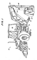
- Fig. 1 illustrates a work vehicle, such as a backhoe loader 10, having a frame 12 to which are mounted ground engaging wheels 14 for supporting and propelling the frame.
- a work vehicle such as a backhoe loader 10
- the backhoe loader 10 is provided with a loader bucket 16 having a suitable loader bucket linkage for manipulating the loader bucket relative to the frame.
- the rear of the vehicle frame 12 is provided with a swing frame 18.
- a boom 20 is pivotally coupled to the swing frame 18, a dipperstick 22 is pivotally connected to the boom at pivot 24 and a bucket 26 is pivotally connected to the dipperstick 22.
- a bucket actuating hydraulic cylinder 28 manipulates the bucket'26 through a bucket linkage.
- the backhoe loader is also provided with two stabilizers 30. The operation of the vehicle is controlled from either an open or closed operator's station 32.
- the swing frame 18 is pivotally coupled to the vehicle frame 12 by a vertical swing frame pivot 34.
- Swing frame hydraulic cylinder 36 pivots the swing frame 18 relative to the vehicle frame 12 about a vertical swing frame axis defined by the swing frame pivot 34.
- the swing frame 18 is provided with two pairs of forwardly projecting vertically arranged portions 38.
- the topmost pair of portions 38 is provided with vertical pin receiving apertures 40.
- Two rearwardly extending portions 42 of the vehicle frame 12 are sandwiched between the pairs of forwardly extending portions 38 to which the swing frame 18 is pivotally coupled by swing frame pivot 34.
- the topmost portion 42 is also provided with a vertical aperture, not shown.
- the vertical aperture on the rearwardly extending portion 42 is aligned with apertures 40 when the swing frame 18 is in a selected locking position on the vehicle frame 12 as defined by the position of the aligned apertures.
- a removable pin 46 having a handle 48 can be inserted into the apertures for locking the swing frame 18 relative to the vehicle frame 12.
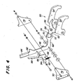
- Lock assembly 50 is pivotally mounted to the swing frame 18 by lock assembly pivot 52.
- the lock assembly 50 comprises an integral piece having two downwardly oriented hooks 54 joined by an actuator plate 56.
- the actuator plate 56 has an enlarged portion 58 located above the swing frame pivot axis defined by the swing frame pivots 34.
- the enlarged portion 58 has a top surface 60 and a bottom surface 62.
- the hooks 54 are designed to engage a catch assembly 64 when the hook assembly is moved into its locked position.
- the catch assembly 64 comprises a transversely extending pin that extends across the width of the boom 20.
- the hook assembly 50 is moved from a locked downwardly tilted position to its unlocked upwardly tilted position by actuator 66.
- the actuator 66 comprises a fork 68 having an upper tine 70 and a lower tine 72.
- the upper tine 70 is provided with a downwardly bent tip 74 that selectively engages the top surface 60 of the enlarged portion 58 of the hook assembly 50.
- the lower time 72 is provided with an upwardly bent tip 76 that engages the bottom surface 62 of the enlarged portion 58 of the hook assembly 50.
- the downwardly bent tip 74 is used to push the actuator plate 56 downwardly driving the hooks 54 upwardly to release the boom 20 from the swing frame 18.
- the upwardly bent tip 76 is used to push the actuator plate 56 upwardly pushing the actuator plate 56 upward and the hooks 54 downwardly to lock the boom 20 to the swing frame 18.
- the actuator 66 is pivotally attached to a bracket 78 that is mounted to the frame 12 of the vehicle 10.
- the bracket 78 is mounted to the backhoe control console 80.
- the actuator 66 is provided with an upwardly extending lever arm 82 having a hand grip 84.
- a latch 86 is pivotally attached to the lever arm 82.
- the latch 86 is provided with a downwardly facing detent 88 which engages catch pin 90 mounted to the bracket.
- the latch 86 has a first position and a second position. The first position corresponds to the locked position of the hook assembly 50, and the second position corresponds to the unlocked position of the hook assembly 50. The second position is defined by the downwardly facing detent 88 engaging the catch pin 90.
- the latch is held in this position by a spring 92 downwardly biasing the downwardly facing detent 88 into engagement with the catch pin 90.
- the spring extends between aperture 94 on the latch 86 and lever arm aperture 96 on which the actuator 66 is pivoted on the bracket 78.
- the latch 86 is provided with an upwardly extending handle 98 that is parallel to the lever arm 82 for releasing the latch 86.
Landscapes
- Engineering & Computer Science (AREA)
- Mechanical Engineering (AREA)
- Mining & Mineral Resources (AREA)
- Civil Engineering (AREA)
- General Engineering & Computer Science (AREA)
- Structural Engineering (AREA)
- Shovels (AREA)
- Lock And Its Accessories (AREA)
- Operation Control Of Excavators (AREA)
- Forklifts And Lifting Vehicles (AREA)
Applications Claiming Priority (2)
| Application Number | Priority Date | Filing Date | Title |
|---|---|---|---|
| US10/106,624 US6648582B2 (en) | 2002-03-26 | 2002-03-26 | Boom lock |
| US106624 | 2002-03-26 |
Publications (3)
| Publication Number | Publication Date |
|---|---|
| EP1348814A2 true EP1348814A2 (fr) | 2003-10-01 |
| EP1348814A3 EP1348814A3 (fr) | 2004-01-14 |
| EP1348814B1 EP1348814B1 (fr) | 2010-07-14 |
Family
ID=27804352
Family Applications (1)
| Application Number | Title | Priority Date | Filing Date |
|---|---|---|---|
| EP03006322A Expired - Lifetime EP1348814B1 (fr) | 2002-03-26 | 2003-03-20 | Dispositif de verrouillage pour une flèche |
Country Status (4)
| Country | Link |
|---|---|
| US (1) | US6648582B2 (fr) |
| EP (1) | EP1348814B1 (fr) |
| DE (1) | DE60333321D1 (fr) |
| ES (1) | ES2348227T3 (fr) |
Cited By (1)
| Publication number | Priority date | Publication date | Assignee | Title |
|---|---|---|---|---|
| GB2512414A (en) * | 2013-03-22 | 2014-10-01 | Cumitas Arge Muhendislik Bilisim Yazilim Danismanlik Sanayi Ve Ticaret Ltd Sti | A locking system |
Families Citing this family (8)
| Publication number | Priority date | Publication date | Assignee | Title |
|---|---|---|---|---|
| JP4247211B2 (ja) * | 2005-07-05 | 2009-04-02 | ヤンマー株式会社 | トラクタ・ローダ・バックホーにおける掘削装置のロック機構 |
| US7618229B2 (en) | 2007-06-27 | 2009-11-17 | Deere & Company | Boom lock for work machine and associated method |
| KR100979429B1 (ko) * | 2008-02-27 | 2010-09-02 | 볼보 컨스트럭션 이키프먼트 홀딩 스웨덴 에이비 | 건설기계의 상부프레임 |
| US8998559B2 (en) * | 2011-09-16 | 2015-04-07 | Deere & Company | Reduced effort manual boom lock |
| CA2917189A1 (fr) | 2013-07-16 | 2015-01-22 | 3M Innovative Properties Company | Enceinte de telecommunication pour connexion externe |
| US10450717B1 (en) | 2019-04-12 | 2019-10-22 | Deere & Company | Attachment assembly for a work vehicle with reinforcement members |
| JP2024118235A (ja) * | 2023-02-20 | 2024-08-30 | 日立建機株式会社 | 作業機械 |
| CN116905586B (zh) * | 2023-08-21 | 2025-08-15 | 三一重机有限公司 | 动臂锁止组件及作业机械 |
Family Cites Families (6)
| Publication number | Priority date | Publication date | Assignee | Title |
|---|---|---|---|---|
| US4225282A (en) | 1978-06-26 | 1980-09-30 | Ford Motor Company | Backhoe boom transport locking means |
| US4227852A (en) * | 1979-01-23 | 1980-10-14 | J. I. Case Company | Releasable backhoe boom lock |
| US4260321A (en) | 1979-09-04 | 1981-04-07 | Deere & Company | Lock mechanism for securing a backhoe boom and swing frame for transport |
| US4887938A (en) * | 1988-08-01 | 1989-12-19 | Caterpillar Inc. | Controllable locking apparatus for implement carrying work vehicle |
| US5064339A (en) | 1991-01-02 | 1991-11-12 | Deere & Company | Backhoe boom lock |
| US5967737A (en) | 1997-10-31 | 1999-10-19 | Deere & Company | Backhoe boom lock |
-
2002
- 2002-03-26 US US10/106,624 patent/US6648582B2/en not_active Expired - Lifetime
-
2003
- 2003-03-20 EP EP03006322A patent/EP1348814B1/fr not_active Expired - Lifetime
- 2003-03-20 DE DE60333321T patent/DE60333321D1/de not_active Expired - Lifetime
- 2003-03-20 ES ES03006322T patent/ES2348227T3/es not_active Expired - Lifetime
Cited By (2)
| Publication number | Priority date | Publication date | Assignee | Title |
|---|---|---|---|---|
| GB2512414A (en) * | 2013-03-22 | 2014-10-01 | Cumitas Arge Muhendislik Bilisim Yazilim Danismanlik Sanayi Ve Ticaret Ltd Sti | A locking system |
| GB2512414B (en) * | 2013-03-22 | 2016-08-10 | Cumitas Arge Muhendislik Bilisim Yazilim Danismanlik Sanayi Ve Ticaret Ltd Sti | A locking system |
Also Published As
| Publication number | Publication date |
|---|---|
| US6648582B2 (en) | 2003-11-18 |
| DE60333321D1 (de) | 2010-08-26 |
| EP1348814B1 (fr) | 2010-07-14 |
| EP1348814A3 (fr) | 2004-01-14 |
| ES2348227T3 (es) | 2010-12-01 |
| US20030185661A1 (en) | 2003-10-02 |
Similar Documents
| Publication | Publication Date | Title |
|---|---|---|
| US4643631A (en) | Quick coupling and release mechanism for buckets | |
| EP0405813B1 (fr) | Dispositif d'attelage d'un outil de travail | |
| US4810162A (en) | Mounting a working implement | |
| US5564885A (en) | Multipurpose work attachment for a front end loader | |
| US8024875B2 (en) | Compact excavator implement interface | |
| US5599158A (en) | Linkage arrangement for a wheel loader | |
| US3984016A (en) | Attachment mounting for end loader | |
| US6648582B2 (en) | Boom lock | |
| US4373852A (en) | Quick coupling and release mechanism for buckets | |
| US5967737A (en) | Backhoe boom lock | |
| US7832127B2 (en) | Apparatus for attaching a work tool to a loader | |
| CA2175409C (fr) | Tringlerie de raccordement du godet d'une excavatrice | |
| US6601891B1 (en) | Grapple attachment | |
| US20110262256A1 (en) | Latching System For Automatically Securing Front-Mounted Loader Mast To Tractor Mounting Frame | |
| WO1988001322A1 (fr) | Attache amelioree | |
| JP2008025161A (ja) | 作業車 | |
| US6332748B1 (en) | Rotating pawl tool latch | |
| CA1132495A (fr) | Mecanisme de calage d'une fleche de retrocaveuse et de sa couronne de giration en cours de deplacement | |
| US7073972B1 (en) | Conversion plate with schur-lock pin mechanism | |
| CN205000380U (zh) | 用于机器的机具系统 | |
| JPH0243418A (ja) | フロントローダの姿勢制御装置 | |
| US8998559B2 (en) | Reduced effort manual boom lock | |
| US4966518A (en) | Apparatus for controlling posture of front loader | |
| CA1298815C (fr) | Commande de positionnement pour chargeuse frontale | |
| US20020192065A1 (en) | Quick attach grapple apparatus |
Legal Events
| Date | Code | Title | Description |
|---|---|---|---|
| PUAI | Public reference made under article 153(3) epc to a published international application that has entered the european phase |
Free format text: ORIGINAL CODE: 0009012 |
|
| AK | Designated contracting states |
Kind code of ref document: A2 Designated state(s): AT BE BG CH CY CZ DE DK EE ES FI FR GB GR HU IE IT LI LU MC NL PT SE SI SK TR |
|
| AX | Request for extension of the european patent |
Extension state: AL LT LV MK RO |
|
| PUAL | Search report despatched |
Free format text: ORIGINAL CODE: 0009013 |
|
| AK | Designated contracting states |
Kind code of ref document: A3 Designated state(s): AT BE BG CH CY CZ DE DK EE ES FI FR GB GR HU IE IT LI LU MC NL PT SE SI SK TR |
|
| AX | Request for extension of the european patent |
Extension state: AL LT LV MK RO |
|
| 17P | Request for examination filed |
Effective date: 20040714 |
|
| AKX | Designation fees paid |
Designated state(s): DE ES FR GB IT |
|
| GRAP | Despatch of communication of intention to grant a patent |
Free format text: ORIGINAL CODE: EPIDOSNIGR1 |
|
| GRAS | Grant fee paid |
Free format text: ORIGINAL CODE: EPIDOSNIGR3 |
|
| GRAA | (expected) grant |
Free format text: ORIGINAL CODE: 0009210 |
|
| AK | Designated contracting states |
Kind code of ref document: B1 Designated state(s): DE ES FR GB IT |
|
| REG | Reference to a national code |
Ref country code: GB Ref legal event code: FG4D |
|
| REF | Corresponds to: |
Ref document number: 60333321 Country of ref document: DE Date of ref document: 20100826 Kind code of ref document: P |
|
| PLBE | No opposition filed within time limit |
Free format text: ORIGINAL CODE: 0009261 |
|
| STAA | Information on the status of an ep patent application or granted ep patent |
Free format text: STATUS: NO OPPOSITION FILED WITHIN TIME LIMIT |
|
| 26N | No opposition filed |
Effective date: 20110415 |
|
| REG | Reference to a national code |
Ref country code: DE Ref legal event code: R097 Ref document number: 60333321 Country of ref document: DE Effective date: 20110415 |
|
| PGFP | Annual fee paid to national office [announced via postgrant information from national office to epo] |
Ref country code: DE Payment date: 20140219 Year of fee payment: 12 |
|
| PGFP | Annual fee paid to national office [announced via postgrant information from national office to epo] |
Ref country code: ES Payment date: 20140326 Year of fee payment: 12 Ref country code: FR Payment date: 20140317 Year of fee payment: 12 Ref country code: IT Payment date: 20140321 Year of fee payment: 12 |
|
| REG | Reference to a national code |
Ref country code: DE Ref legal event code: R119 Ref document number: 60333321 Country of ref document: DE |
|
| PG25 | Lapsed in a contracting state [announced via postgrant information from national office to epo] |
Ref country code: IT Free format text: LAPSE BECAUSE OF NON-PAYMENT OF DUE FEES Effective date: 20150320 |
|
| REG | Reference to a national code |
Ref country code: FR Ref legal event code: ST Effective date: 20151130 |
|
| PG25 | Lapsed in a contracting state [announced via postgrant information from national office to epo] |
Ref country code: DE Free format text: LAPSE BECAUSE OF NON-PAYMENT OF DUE FEES Effective date: 20151001 |
|
| PG25 | Lapsed in a contracting state [announced via postgrant information from national office to epo] |
Ref country code: FR Free format text: LAPSE BECAUSE OF NON-PAYMENT OF DUE FEES Effective date: 20150331 |
|
| REG | Reference to a national code |
Ref country code: ES Ref legal event code: FD2A Effective date: 20160531 |
|
| PG25 | Lapsed in a contracting state [announced via postgrant information from national office to epo] |
Ref country code: ES Free format text: LAPSE BECAUSE OF NON-PAYMENT OF DUE FEES Effective date: 20150321 |
|
| PGFP | Annual fee paid to national office [announced via postgrant information from national office to epo] |
Ref country code: GB Payment date: 20170327 Year of fee payment: 15 |
|
| GBPC | Gb: european patent ceased through non-payment of renewal fee |
Effective date: 20180320 |
|
| PG25 | Lapsed in a contracting state [announced via postgrant information from national office to epo] |
Ref country code: GB Free format text: LAPSE BECAUSE OF NON-PAYMENT OF DUE FEES Effective date: 20180320 |