EP1348880A1 - Actuateur motorisé - Google Patents
Actuateur motorisé Download PDFInfo
- Publication number
- EP1348880A1 EP1348880A1 EP03075869A EP03075869A EP1348880A1 EP 1348880 A1 EP1348880 A1 EP 1348880A1 EP 03075869 A EP03075869 A EP 03075869A EP 03075869 A EP03075869 A EP 03075869A EP 1348880 A1 EP1348880 A1 EP 1348880A1
- Authority
- EP
- European Patent Office
- Prior art keywords
- worm wheel
- wheel gear
- gear
- housing
- pin
- Prior art date
- Legal status (The legal status is an assumption and is not a legal conclusion. Google has not performed a legal analysis and makes no representation as to the accuracy of the status listed.)
- Granted
Links
Images



Classifications
-
- F—MECHANICAL ENGINEERING; LIGHTING; HEATING; WEAPONS; BLASTING
- F16—ENGINEERING ELEMENTS AND UNITS; GENERAL MEASURES FOR PRODUCING AND MAINTAINING EFFECTIVE FUNCTIONING OF MACHINES OR INSTALLATIONS; THERMAL INSULATION IN GENERAL
- F16D—COUPLINGS FOR TRANSMITTING ROTATION; CLUTCHES; BRAKES
- F16D28/00—Electrically-actuated clutches
-
- F—MECHANICAL ENGINEERING; LIGHTING; HEATING; WEAPONS; BLASTING
- F16—ENGINEERING ELEMENTS AND UNITS; GENERAL MEASURES FOR PRODUCING AND MAINTAINING EFFECTIVE FUNCTIONING OF MACHINES OR INSTALLATIONS; THERMAL INSULATION IN GENERAL
- F16D—COUPLINGS FOR TRANSMITTING ROTATION; CLUTCHES; BRAKES
- F16D25/00—Fluid-actuated clutches
- F16D25/08—Fluid-actuated clutches with fluid-actuated member not rotating with a clutching member
- F16D2025/081—Hydraulic devices that initiate movement of pistons in secondary cylinders for actuating clutches, i.e. primary cylinders
Definitions
- This invention generally relates to a motor drive device and more particularly, this invention pertains to a motor drive device which includes a worm gear and a worm wheel gear.
- a device including a worm gear and a worm wheel gear is known as a conventional work.
- a driven side is not affected by a load of an output side.
- an automotive clutch operating device is disclosed in an United States Patent No.5135090.
- the automotive clutch operating device is characterized in that a motor rotates a worm wheel gear via a worm gear provided on an output shaft of the motor by engaging with the worm wheel gear.
- a gear lock may be generated between the worm gear and the worm wheel gear.
- the gear lock is, for example a condition that both gears come to lock by high load acting on an engaging part between the worm gear and the worm wheel gear.
- the present invention therefore seeks to provide an improved motor drive device capable of avoiding a gear lock generated by impact force acting on an engaging part of a worm wheel gear, when rotation of the worm wheel gear is restricted.
- a motor drive device includes a housing, a motor fixed to the housing, a shaft including a worm gear and driven by the motor, a worm wheel gear, and a rotation restricting device which restricts a rotational angle of the worm wheel gear.
- the worm wheel gear is provided rotatably within the housing and engages with the worm gear.
- the rotation restricting device is provided between the worm wheel gear and the housing. When rotation of the worm wheel gear is restricted, impact force acting on an engaging part of the worm wheel gear is reduced by an absorbing function the rotation restricting device has.
- the rotation restricting device has a pin provided on a part of the worm wheel gear and a biasing device.
- the biasing device has a concave portion which biases the worm wheel gear by engaging with the pin, and the concave portion is movable relative to the pin.
- a motor drive device 1 is applicable to an automatic clutching device of a vehicle. Additionally, a mechanism of the motor drive device 1 is applicable to a motor drive device which includes a worm gear, a worm wheel gear and a motor and driven by the motor.
- the motor drive device is, for example, applicable to a window regulating device or a switching device of drive system (2WD/4WD) in a vehicle.
- a motor 7 is fixed to a housing 2 and a worm wheel gear 3 having a circular plate shape is provided within the housing 2.
- the worm wheel gear 3 engages with a worm gear 4 on an engaging part 19.
- the worm gear 4 is provided on a shaft 5 and capable of transmitting a driving torque generated by the motor 7 to the worm wheel gear 3.
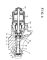
- a motor shaft 6 transmitting the driving torque by the motor 7 is connected coaxially to the shaft 5 (referring to Fig.3).
- the worm wheel gear 3 is supported rotatably by two bearings provided on the housing 2 and a housing cover 2a via a shaft 3a.
- the shaft 3a is through the center of the worm wheel gear 3.
- Two cylinder-shaped pins 8 and 10 are radially provided on the worm wheel gear 3 and project in a direction parallel to the shaft 3a.
- the pin 8 is longer than the pin 10 in the axial direction.
- the stopper 9 is provided on a lateral wall of a concave portion formed within the housing 2. As shown in Fig.1, the pin 10 is connected to a connecting rod 20. When the worm wheel gear 3 rotates, a connecting part between the pin 10 and the connecting rod 20 rotates together. Movement of the connecting rod 20 is restricted in a direction approximately parallel to the motor shaft 6. Consequently, rotational movement of the worm wheel gear 3 is converted into linear movement, and the linear movement is transmitted to an output side of the motor drive device 1.
- a motor drive part 11 is described below.
- axially movable bearings 13 and 16 are mounted on each end part of the shaft 5.
- Dish springs 12 and 15 (cushions) are provided on a part of the housing 2 where the bearings 13 and 16 are located with one end of each of the dish springs 12 and 15 being in contact with a respective bearing 13 or 16.
- the motor shaft 6 has a boss 6a which has a defined width between two flats and is formed on an end of the shaft 6 facing the worm wheel gear 3.
- the shaft 5 is keyed to the motor shaft 6 via a blind axial recess 5a which has similar flats and is formed in an end of the shaft facing the motor . Consequently, the shaft 5 is axially movable relative to the motor shaft 6.
- One end part of the motor shaft 6 is supported by a bearing 22 housed in a motor case 7a, the other end part is supported by a bearing 21 inserted into the housing 2.
- the motor 7 is fixed to the housing 2 via the motor case 7a and a bolt 23.
- the engaging part 19 between the worm gear 4 and the worm wheel gear 3 is provided on a portion between the bearings 13 and 16.
- Fig.4 shows a condition that the rotation of the worm wheel gear 3 is restricted by the stopper 9. Consequently, the stopper 9 or a wall part formed on a concave portion of the housing 2 functions as a stopping device.
- the pin 8 engages with the sleeve 24 via a concave portion formed on the sleeve 24 and facing the center of the worm wheel gear 3.
- the sleeve 24 is provided within the housing 2 and biased in one direction by a coil spring 25.
- the coil spring 25 is provided between the worm wheel gear 3 and the housing 2.
- the spring is received by the sleeve 24 which acts as a spring retainer.
- the spring 25 is received by a spring retainer sleeve 26 having a central cylindrical spring retaining boss.
- the sleeve is pivotally mounted relative to the housing 2 on a boss 27 formed on the housing 2 and facing the worm wheel gear 3. Consequently, the sleeves 24 and 26, the spring 25, and the boss 27 form a biasing device 28 (a biasing means) which biases the worm wheel gear 3 in one direction.
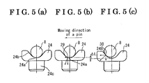
- Fig.5(a), (b) and (c) show a transitional movement of engagement between the pin 8 and the sleeve 24, when the worm wheel gear 3 rotates.
- the concave portion of the sleeve 24 includes an arcuate part 24a and a straight part 24b.
- the arcuate part 24a has a curvature which is equal to or a little larger than a radius of the pin 8.
- the arcuate part 24a is formed on a central part of the sleeve 24 and the straight part 24b is formed adjacent to the arcuate part 24a.
- a smooth boundary is formed between the arcuate part 24a and the straight part 24b.
- the pin 8 presses the sleeve 24 toward a moving direction of the pin 8 (shown in Fig.5), the sleeve 24 is depressed, and the spring 25 is compressed.
- the contacting point between the pin 8 and the sleeve 24 shifts to a point 30 on the straight part 24b of the concave portion of the sleeve 24, as shown in Fig.5(c).
- Impact force generated on the contacting point between the pin 8 and the sleeve 24 and leading to displacement ⁇ L of the sleeve 24 is absorbed by the spring 25. Consequently, by absorbing the impact force, the rotation of the worm wheel gear 3 can be restricted with the gear lock being avoided on the engaging part 19 between the worm gear 4 and the worm wheel gear 3.
- the rotation of the worm wheel gear3 is absorbed by movement of the pin 8 relative to the sleeve 24.
- the sleeve includes the arcuate part 24a and the straight part 24b formed continuously, so the rotation of the worm wheel gear 3 is not stopped immediately by a shift of the pin 8 from the arcuate part 24a to the straight part 24b when the rotation of the worm wheel gear 3 is restricted by the stopper 9. Consequently, the impact force generated on the contacting point between the pin 8 and the sleeve 24 is reduced smoothly by an absorbing function including the spring 25.
- the impact force acting on the engaging part 19 is also reduced, a gear lock on the engaging part 19 can be prevented, and the engaging part 19 can be protected absolutely.
- This present invention is applicable to a system, for example, which generates a force and a displacement via a worm gear and a worm wheel gear by a motor and needs to restrict rotation of the worm wheel gear functionally.
Landscapes
- Engineering & Computer Science (AREA)
- General Engineering & Computer Science (AREA)
- Physics & Mathematics (AREA)
- Electromagnetism (AREA)
- Mechanical Engineering (AREA)
- Gear Transmission (AREA)
- Connection Of Motors, Electrical Generators, Mechanical Devices, And The Like (AREA)
Applications Claiming Priority (2)
| Application Number | Priority Date | Filing Date | Title |
|---|---|---|---|
| JP2002089379A JP3925270B2 (ja) | 2002-03-27 | 2002-03-27 | モータ駆動装置 |
| JP2002089379 | 2002-03-27 |
Publications (2)
| Publication Number | Publication Date |
|---|---|
| EP1348880A1 true EP1348880A1 (fr) | 2003-10-01 |
| EP1348880B1 EP1348880B1 (fr) | 2005-08-17 |
Family
ID=27800490
Family Applications (1)
| Application Number | Title | Priority Date | Filing Date |
|---|---|---|---|
| EP03075869A Expired - Lifetime EP1348880B1 (fr) | 2002-03-27 | 2003-03-27 | Actuateur motorisé |
Country Status (3)
| Country | Link |
|---|---|
| EP (1) | EP1348880B1 (fr) |
| JP (1) | JP3925270B2 (fr) |
| DE (1) | DE60301290T2 (fr) |
Cited By (2)
| Publication number | Priority date | Publication date | Assignee | Title |
|---|---|---|---|---|
| EP2060817A1 (fr) * | 2007-11-15 | 2009-05-20 | Yamaha Hatsudoki Kabushiki Kaisha | Dispositif à commande d'embrayage et véhicule doté de celui-ci |
| EP3974672A3 (fr) * | 2020-09-29 | 2022-08-31 | Aisin Corporation | Commande d'actionnement d'un maître cylindre d'un embrayage actionné par fluide |
Families Citing this family (2)
| Publication number | Priority date | Publication date | Assignee | Title |
|---|---|---|---|---|
| JP4846458B2 (ja) * | 2006-06-07 | 2011-12-28 | 本田技研工業株式会社 | クラッチアクチュエータ |
| DE102015224612A1 (de) * | 2015-12-08 | 2017-06-08 | Zf Friedrichshafen Ag | Betätigungseinheit, Kupplung sowie Kraftfahrzeug |
Citations (2)
| Publication number | Priority date | Publication date | Assignee | Title |
|---|---|---|---|---|
| US5680916A (en) * | 1994-09-22 | 1997-10-28 | Fichtel & Sachs Ag | Motor vehicle clutch assembly having a hydraulic actuator which hydraulic actuator has a transmission |
| DE19742477A1 (de) * | 1997-09-26 | 1999-04-08 | Mannesmann Sachs Ag | Stelleinrichtung |
-
2002
- 2002-03-27 JP JP2002089379A patent/JP3925270B2/ja not_active Expired - Lifetime
-
2003
- 2003-03-27 EP EP03075869A patent/EP1348880B1/fr not_active Expired - Lifetime
- 2003-03-27 DE DE60301290T patent/DE60301290T2/de not_active Expired - Lifetime
Patent Citations (2)
| Publication number | Priority date | Publication date | Assignee | Title |
|---|---|---|---|---|
| US5680916A (en) * | 1994-09-22 | 1997-10-28 | Fichtel & Sachs Ag | Motor vehicle clutch assembly having a hydraulic actuator which hydraulic actuator has a transmission |
| DE19742477A1 (de) * | 1997-09-26 | 1999-04-08 | Mannesmann Sachs Ag | Stelleinrichtung |
Cited By (3)
| Publication number | Priority date | Publication date | Assignee | Title |
|---|---|---|---|---|
| EP2060817A1 (fr) * | 2007-11-15 | 2009-05-20 | Yamaha Hatsudoki Kabushiki Kaisha | Dispositif à commande d'embrayage et véhicule doté de celui-ci |
| US8127906B2 (en) | 2007-11-15 | 2012-03-06 | Yamaha Hatsudoki Kabushiki Kaisha | Clutch drive device and vehicle equipped with the same |
| EP3974672A3 (fr) * | 2020-09-29 | 2022-08-31 | Aisin Corporation | Commande d'actionnement d'un maître cylindre d'un embrayage actionné par fluide |
Also Published As
| Publication number | Publication date |
|---|---|
| JP2003287087A (ja) | 2003-10-10 |
| JP3925270B2 (ja) | 2007-06-06 |
| DE60301290D1 (de) | 2005-09-22 |
| DE60301290T2 (de) | 2006-03-02 |
| EP1348880B1 (fr) | 2005-08-17 |
Similar Documents
| Publication | Publication Date | Title |
|---|---|---|
| US8857595B2 (en) | Load torque lock and apparatus having load torque lock | |
| US6253894B1 (en) | Two-side adjustment drive mechanism | |
| US8678155B2 (en) | Clutch unit | |
| EP2371602A1 (fr) | Obturateur de calandre amovible pour véhicule | |
| US20110024252A1 (en) | Clutch actuating apparatus for double clutch transmission | |
| US7114778B2 (en) | Drive having a sliding element for a vehicle seat adjuster | |
| KR102547463B1 (ko) | 역입력 차단 클러치 | |
| EP0684356B1 (fr) | Mecanisme d'entrainement d'une serrure de porte | |
| EP1365176A2 (fr) | Appareil entraíné par moteur | |
| JP2009270709A (ja) | 電動リニアアクチュエータ | |
| JP3469276B2 (ja) | 逆転防止軸受装置 | |
| EP1348880B1 (fr) | Actuateur motorisé | |
| CN116635642A (zh) | 反向输入切断离合器 | |
| US5979261A (en) | Positioning device for shifting gears in a transmission having an output component capable of two types of motion | |
| EP1128006B1 (fr) | Ensemble actionneur | |
| JP7095402B2 (ja) | 逆入力ブレーキ機構および電動式ブレーキ装置 | |
| EP1691100A1 (fr) | Embrayage bidirectionel pour transmission | |
| US6604619B1 (en) | Two-directional manual drive | |
| WO2021187515A1 (fr) | Dispositif de verrouillage de rotation | |
| EP1411203A1 (fr) | Embrayage | |
| EP0884494A1 (fr) | Mécanisme de blocage | |
| EP1529701B1 (fr) | Arrangement d'un arbre de sortie, dispositif moteur et moteur d'essuie-glace | |
| EP2108854B1 (fr) | Appareil de prise de force et embrayage | |
| JP2003278793A (ja) | クラッチ装置 | |
| EP1717398A2 (fr) | Embrayage pour un moteur de lève-vitre |
Legal Events
| Date | Code | Title | Description |
|---|---|---|---|
| PUAI | Public reference made under article 153(3) epc to a published international application that has entered the european phase |
Free format text: ORIGINAL CODE: 0009012 |
|
| AK | Designated contracting states |
Kind code of ref document: A1 Designated state(s): AT BE BG CH CY CZ DE DK EE ES FI FR GB GR HU IE IT LI LU MC NL PT SE SI SK TR |
|
| AX | Request for extension of the european patent |
Extension state: AL LT LV MK RO |
|
| 17P | Request for examination filed |
Effective date: 20040119 |
|
| 17Q | First examination report despatched |
Effective date: 20040302 |
|
| AKX | Designation fees paid |
Designated state(s): DE FR GB |
|
| GRAP | Despatch of communication of intention to grant a patent |
Free format text: ORIGINAL CODE: EPIDOSNIGR1 |
|
| RAP1 | Party data changed (applicant data changed or rights of an application transferred) |
Owner name: AISIN SEIKI KABUSHIKI KAISHA |
|
| GRAS | Grant fee paid |
Free format text: ORIGINAL CODE: EPIDOSNIGR3 |
|
| GRAA | (expected) grant |
Free format text: ORIGINAL CODE: 0009210 |
|
| AK | Designated contracting states |
Kind code of ref document: B1 Designated state(s): DE FR GB |
|
| REG | Reference to a national code |
Ref country code: GB Ref legal event code: FG4D |
|
| REF | Corresponds to: |
Ref document number: 60301290 Country of ref document: DE Date of ref document: 20050922 Kind code of ref document: P |
|
| ET | Fr: translation filed | ||
| PLBE | No opposition filed within time limit |
Free format text: ORIGINAL CODE: 0009261 |
|
| STAA | Information on the status of an ep patent application or granted ep patent |
Free format text: STATUS: NO OPPOSITION FILED WITHIN TIME LIMIT |
|
| 26N | No opposition filed |
Effective date: 20060518 |
|
| GBPC | Gb: european patent ceased through non-payment of renewal fee |
Effective date: 20070327 |
|
| PG25 | Lapsed in a contracting state [announced via postgrant information from national office to epo] |
Ref country code: GB Free format text: LAPSE BECAUSE OF NON-PAYMENT OF DUE FEES Effective date: 20070327 |
|
| REG | Reference to a national code |
Ref country code: DE Ref legal event code: R084 Ref document number: 60301290 Country of ref document: DE Effective date: 20121122 |
|
| REG | Reference to a national code |
Ref country code: FR Ref legal event code: PLFP Year of fee payment: 14 |
|
| REG | Reference to a national code |
Ref country code: FR Ref legal event code: PLFP Year of fee payment: 15 |
|
| REG | Reference to a national code |
Ref country code: FR Ref legal event code: PLFP Year of fee payment: 16 |
|
| PGFP | Annual fee paid to national office [announced via postgrant information from national office to epo] |
Ref country code: DE Payment date: 20220203 Year of fee payment: 20 |
|
| PGFP | Annual fee paid to national office [announced via postgrant information from national office to epo] |
Ref country code: FR Payment date: 20220210 Year of fee payment: 20 |
|
| REG | Reference to a national code |
Ref country code: DE Ref legal event code: R071 Ref document number: 60301290 Country of ref document: DE |