EP1348942A2 - Verfahren und Vorrichtung zur Definition von elastischen Deformationen und Messung des inneren Winkels eines Kreiselverdichters - Google Patents
Verfahren und Vorrichtung zur Definition von elastischen Deformationen und Messung des inneren Winkels eines Kreiselverdichters Download PDFInfo
- Publication number
- EP1348942A2 EP1348942A2 EP03396025A EP03396025A EP1348942A2 EP 1348942 A2 EP1348942 A2 EP 1348942A2 EP 03396025 A EP03396025 A EP 03396025A EP 03396025 A EP03396025 A EP 03396025A EP 1348942 A2 EP1348942 A2 EP 1348942A2
- Authority
- EP
- European Patent Office
- Prior art keywords
- gyratory compactor
- loading device
- angle
- gyration
- accordance
- Prior art date
- Legal status (The legal status is an assumption and is not a legal conclusion. Google has not performed a legal analysis and makes no representation as to the accuracy of the status listed.)
- Granted
Links
- 238000000034 method Methods 0.000 title claims abstract description 39
- 230000005489 elastic deformation Effects 0.000 title claims abstract description 26
- 238000011068 loading method Methods 0.000 claims abstract description 99
- 238000005259 measurement Methods 0.000 claims description 18
- 230000003287 optical effect Effects 0.000 claims description 5
- 238000012360 testing method Methods 0.000 description 20
- 238000005056 compaction Methods 0.000 description 16
- 239000000523 sample Substances 0.000 description 14
- 238000012545 processing Methods 0.000 description 12
- 230000033001 locomotion Effects 0.000 description 11
- 238000005452 bending Methods 0.000 description 7
- 239000000203 mixture Substances 0.000 description 7
- 238000004364 calculation method Methods 0.000 description 5
- 239000010426 asphalt Substances 0.000 description 4
- 238000010276 construction Methods 0.000 description 4
- 239000002689 soil Substances 0.000 description 2
- 229910000831 Steel Inorganic materials 0.000 description 1
- XAGFODPZIPBFFR-UHFFFAOYSA-N aluminium Chemical compound [Al] XAGFODPZIPBFFR-UHFFFAOYSA-N 0.000 description 1
- 229910052782 aluminium Inorganic materials 0.000 description 1
- 239000004411 aluminium Substances 0.000 description 1
- 238000004590 computer program Methods 0.000 description 1
- 238000013480 data collection Methods 0.000 description 1
- 238000002474 experimental method Methods 0.000 description 1
- 230000006870 function Effects 0.000 description 1
- 239000012535 impurity Substances 0.000 description 1
- 230000001939 inductive effect Effects 0.000 description 1
- 239000000463 material Substances 0.000 description 1
- 238000013208 measuring procedure Methods 0.000 description 1
- 239000002245 particle Substances 0.000 description 1
- 239000004033 plastic Substances 0.000 description 1
- 239000011343 solid material Substances 0.000 description 1
- 239000010959 steel Substances 0.000 description 1
- 239000000126 substance Substances 0.000 description 1
- 238000010998 test method Methods 0.000 description 1
- 238000012546 transfer Methods 0.000 description 1
Images


Classifications
-
- G—PHYSICS
- G01—MEASURING; TESTING
- G01N—INVESTIGATING OR ANALYSING MATERIALS BY DETERMINING THEIR CHEMICAL OR PHYSICAL PROPERTIES
- G01N3/00—Investigating strength properties of solid materials by application of mechanical stress
- G01N3/56—Investigating resistance to wear or abrasion
- G01N3/565—Investigating resistance to wear or abrasion of granular or particulate material
-
- G—PHYSICS
- G01—MEASURING; TESTING
- G01N—INVESTIGATING OR ANALYSING MATERIALS BY DETERMINING THEIR CHEMICAL OR PHYSICAL PROPERTIES
- G01N1/00—Sampling; Preparing specimens for investigation
- G01N1/28—Preparing specimens for investigation including physical details of (bio-)chemical methods covered elsewhere, e.g. G01N33/50, C12Q
- G01N1/286—Preparing specimens for investigation including physical details of (bio-)chemical methods covered elsewhere, e.g. G01N33/50, C12Q involving mechanical work, e.g. chopping, disintegrating, compacting, homogenising
-
- G—PHYSICS
- G01—MEASURING; TESTING
- G01N—INVESTIGATING OR ANALYSING MATERIALS BY DETERMINING THEIR CHEMICAL OR PHYSICAL PROPERTIES
- G01N3/00—Investigating strength properties of solid materials by application of mechanical stress
- G01N3/08—Investigating strength properties of solid materials by application of mechanical stress by applying steady tensile or compressive forces
-
- G—PHYSICS
- G01—MEASURING; TESTING
- G01N—INVESTIGATING OR ANALYSING MATERIALS BY DETERMINING THEIR CHEMICAL OR PHYSICAL PROPERTIES
- G01N2203/00—Investigating strength properties of solid materials by application of mechanical stress
- G01N2203/0014—Type of force applied
- G01N2203/0026—Combination of several types of applied forces
- G01N2203/0028—Rotation and bending
-
- G—PHYSICS
- G01—MEASURING; TESTING
- G01N—INVESTIGATING OR ANALYSING MATERIALS BY DETERMINING THEIR CHEMICAL OR PHYSICAL PROPERTIES
- G01N2203/00—Investigating strength properties of solid materials by application of mechanical stress
- G01N2203/02—Details not specific for a particular testing method
- G01N2203/06—Indicating or recording means; Sensing means
- G01N2203/067—Parameter measured for estimating the property
- G01N2203/0682—Spatial dimension, e.g. length, area, angle
Definitions
- the present invention relates to a method for accurately inducing elastic deformations of a gyratory compactor and measuring the internal angle of gyration.
- the internal angle of gyration is the angle formed between the axis of a cylindrical mold and the end plates of the mold.
- a gyratory compactor is used for defining properties of compaction of various masses of soil and similar substances, such as bituminous asphalt.
- the specimen mold of a gyratory compactor is filled with mass specimen.
- the specimen is compressed under vertical pressure and the so called gyratory movement, which causes shear strain across the specimen. These actions make the particles of the specimen to move in respect with each other finding their positions tighter to each other, compacting the mass specimen and leading to increasing density.
- the gyratory compactor frame is experiencing forces due to deformation resistance of the specimen. These forces are greater where the pressure and cross-sectional deformation due to it are greatest.
- a change in the angle of gyration is usually the most significant factor of error having influence on results in measuring compaction properties in gyratory compactor.
- the angle of gyration in the end of a test may be more than 10% smaller than in the beginning of the test.
- the compaction results of tests carried out with these kinds of gyratory compactors are examined, however, assuming that the angle of gyration has remained equal during the whole length of the test. Therefore, many different models of gyratory compactors at present give deviating results to each other in measuring compaction properties. The situation is especially serious when the mass specimen is causing heavier loadings or variable loadings to the gyratory compactor (i.e. a "stiff" or coarse mixture).
- correlation between the angle of gyration of gyratory compactors is defined by measuring the compacted density of hot mix mass specimens from the same source with different gyratory compactors. This aims to clarify differences between gyratory compactors by comparing test results of different gyratory compactors. Sometimes based on these differences the elastic properties of different gyratory compactors as well as other quality factors are tried to be determined. This kind of studying of tests and their results is rather troublesome and slow. Furthermore, measuring results gathered with this kind of method are inaccurate, among other things, because properties and density of mass specimen vary uncontrollably and relatively much, although the mass specimen has been taken from the same mass specimen source.
- An angle measurement device which can be put into a specimen mold of a gyratory compactor is known from the patent US 6477783.
- the device is placed inside a cylinder mold in the bottom or top against the bottom or top piston along with the asphalt mixture.
- the measuring result from the movable probe tip in relation to the position of the fixed probe tip is in proportion to the angle of gyration of the gyratory compactor.
- the device and a hot mix mass specimen is placed in the specimen mold with the hot mix placed above or under the measuring device.
- the gyratory compactor is then operated in a way corresponding to the normal compacting of mass specimen. From the position between the movable probe tip and the fixed probe tip the angle of gyration of the gyratory compactor is defined during the compaction of mass specimen in the specimen cylinder mold.
- the measuring device takes part of the space meant for a mass specimen, so that a mass specimen smaller than normal must be used or the compaction pistons are further away from each other than during normal compaction. Therefore angle measurements taken do not correspond to the actual compacting situation of a mass specimen.
- the measuring device is shorter in order to decrease the above mentioned disadvantages, the probe tips must be adjusted closer to each other on the vertical axis, which creates more inaccuracy in measuring.
- the magnitude of loading from a mass specimen to the gyratory compactor is unknown beforehand, and the mass specimen to be placed above or under the measuring device is different by density properties every time when measured, because every time the measurement is made there must be a new mass specimen in the specimen cylinder mold. Therefore, while using the device presented in the patent above several rather long individual test measurements must be carried out if elastic deformations of a gyratory compactor is wanted to define reliably and exactly enough. Furthermore, due to its construction the measuring device is exposed to heat damage while using hot asphalt specimens. Also impurities may stick to probe tips affecting the measuring accuracy. These all are additional to elements of uncertainty in use of the measuring device as well as difficulties in measuring process presented in patent above.
- the purpose of this invention is to provide a method and a device, which reduces or eliminates earlier mentioned problems connected with present methods of defining elastic deformations and internal angles of gyratory compactors.
- the purpose of the invention is to provide a method and a device, by use of which the elastic properties of a gyratory compactor frame can be defined. Further by using the method and device, important factors expressing the quality of a gyratory compactor depending on elastic properties are easily and reliably defined.
- the purpose of the invention is to provide a method, which is quick and easy to use as well as a device, which is accurate and reliable but simple and advantageous by construction.
- Characteristic to the method in accordance with the invention is that a mass specimen is replaced with a load generating device (loading device), where the load level on the gyratory compactor is known, and that the gyratory compactor is used while the load generating device is inside the mold in the gyratory compactor.
- a load generating device where the load level on the gyratory compactor is known, instead of a mass specimen when defining elastic properties and integral angle, errors due to changes in stiffness and density of a mass specimen are eliminated.
- the beforehand known loading caused by the load generating device may easily be changed to another known value in order to find out reliably and exactly the correlation between elastic deformations of a gyratory compactor and the magnitude of load.
- At least two measurements of the angle of gyration of a gyratory compactor are carried out with different generated load values. This way it is possible to find out the influence of the change in load on elastic deformations of a gyratory compactor and the magnitude of elastic deformation as a function of load can be defined. By means of connection between the load and elastic deformation achieved this way it is possible to understand the meaning of elastic deformations caused by various masses and their influence on compaction properties to be defined.
- correlation between the angle of gyration and the load may be taken into account in calculations of density properties after measurements such that the actual angle of gyration defined based on elastic deformations is used in calculations. This improves the reliability and accuracy of the results of the experiment on gyratory compaction.
- the load from the load generating device is changed by changing at least one of the contact points of the load generating device and the gyratory compactor.
- the change of the contact point may be carried out between two measurements of defining the elastic deformation simply, easy and quickly.
- the value of various loads created by changing the contact point may be defined by simple calculations very accurate when the pressing force on the cover and bottom of the specimen cylinder mold is known.
- the contact points between the load generating device and the gyratory compactor are changed by mounting at least one additional part changing the contact points of the load generating device. This way changing the contact points may be carried out easy, quickly and accurately repeatable.
- the angle of gyration of the gyratory compactor is measured with a length dial gauge.
- the dial gauge may be placed inside a standard size specimen cylinder mold easy and fixed to a suitable place with a simple fixing construction such that the tip of the dial gauge measures the angle between the cover or bottom of the specimen cylinder mold and the sidewall of specimen cylinder mold such that the angle of gyration may be defined with simple calculations from that result.
- results from the dial gauge may relatively easy be either collected to the memory of the device or transmitted to a processing unit for measuring results in real time outside the gyratory compactor.
- the angle of gyration of a gyratory compactor is measured by means of optical measuring elements mounted in the specimen cylinder mold.
- the measuring of the angle of gyration may be carried out extremely accurately, because in these kinds of measurements the changes in elastic deformations may be examined while optically magnified.
- the transfer of measuring information by means of optical measuring elements outside the specimen cylinder mold may be carried out simply and advantageously by reflecting the light beam describing the changes due to elastic deformations through an opening in the specimen cylinder mold outside the gyratory compactor.
- Characteristic to a device in accordance with invention is the fact that the device includes at least one load generating device to be placed inside the specimen cylinder mold of a gyratory compactor. While using the method in accordance with the invention it is possible by means of a load generating device to expose to the gyratory compactor such load corresponding the load of the mass specimen, very easy and simply, and so defining the elastic deformations of the gyratory compactor by measuring the value of the angle of gyration. This may be carried out reliably and exactly without troublesome and slow comparing measurements or use of hot mix as in present methods.
- a cylindrical part which can be placed inside the specimen cylinder mold moving with minimal clearance.
- This kind of part is suitable and easy to be placed inside a specimen cylinder mold of most present known gyratory compactors and this kind of part may be made to cause loads closely resembling mass specimen while pressed between the cover and the bottom of a specimen cylinder mold in a gyratory compactor.
- this kind of cylindrical part it is easy to install measuring devices/device with which it is possible to measure the actual internal angle of gyration of a gyratory compactor during the use of a gyratory compactor.
- the character and the magnitude of loads from this kind of load generating device may easily be changed to resemble the changes caused by density and stiffness of the mass specimen by changing the contact points between the cover and the bottom and the load generating device.
- the load generating device includes at least one additional part which can be mounted to the load generating device in order to change the magnitude of loads caused by the load generating device to the gyratory compactor.
- additional parts it is possible to change contact points between the loading device and the bottom and the cover. In that way loads caused by the loading device to the specimen cylinder mold, cover and bottom are similar to the changes caused by the changes of properties of mass specimen.
- the magnitude of the load is easy to be defined by calculations from pressing forces against the bottom and the cover. Due to this it is possible by means of this kind of equipment to define the correlation between elastic deformations of a gyratory compactor and the magnitude of the load of mass specimen reliably and exactly.
- a device in accordance with the method in accordance with the invention includes a loading device suitable to be placed into a specimen cylinder mold of a gyratory compactor as well as measuring elements for measuring the angle of gyration and a processing unit for measuring results to be connected to measuring elements for processing the measuring results of the angle of gyration and converting to elastic deformations of a gyratory compactor.
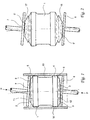
- FIG 1 there is a loading device 1 placed into a specimen cylinder mold M of a gyratory compactor.
- the loading device in accordance with fig. 1 has been made of suitable solid material, such as steel, aluminium or plastic, with a body in the shape of a cylinder with head surfaces 2 and 3, as well as casing surface 4.
- the head surfaces 2 and 3 extend or project from respective ends of the loading device body.
- the diameter of the loading device is such that it can be placed inside a standard size specimen cylinder mold of a gyratory compactor without clearance but easy to move inside the cylinder mold.
- There are chamfers 5 and 6 on the edge of the head surfaces of the loading device so that the cover 7 and the bottom 8 of the specimen cylinder mold make contact with the loading device controlled at the contact points 9.
- the loading device includes as well a groove 10 made to the central area of the casing surface. The meaning of it is to prevent the contact between the casing surface with the specimen cylinder mold at the central area of the loading device, such that defining of loads between the loading device and the specimen cylinder mold would be as exact and easy as possible, There are hollows 11 and 12 on the head surfaces 2 and 3. The shape and depth of them allows to adjust ring like additional parts (not included in fig.
- Head surfaces 2 and 3 can be formed integrally with the body, or attached to or otherwise fixedly positioned at the respective ends of the loading device body.
- the additional parts in the loading device in accordance with fig. 1 are ring like parts made such that they reach from the bottom of hollows 11 and 12 outside the head surfaces 2 and 3 on vertical axis.
- Fig. 2 illustrates, as an example of these kinds of additional parts, 17 and 18 added to a loading device in accordance with fig. 1. While the loading device is inside the specimen cylinder mold and the additional parts 17 and 18 are placed in the loading device, the cover 7 and bottom 8 the of the specimen cylinder mold are in contact only with the additional parts 17 and 18 at the contact points 9'. While comparing figures 1 and 2 one can see that the additional parts 17 and 18 added to the loading device causes the contact point between the cover 7 and the bottom 8 and the loading device to change in extent of the radius of the loading device.
- the additional parts 17 and 18 are placed inside the hollows 11 and 12 suitably without clearance while mounted in the loading device. Therefore the contact point of the cover 7 and the bottom 8 of the specimen cylinder mold and the additional parts stay always in a constant distance from the vertical center line of the loading device. Therefore the bending moments due to the loading device will remain constant considering that the force P on the cover and the bottom is not changed. Therefore the bending moments due to the loading device may be exactly and reliably defined beforehand also where the additional parts 17 and 18 are used in the loading device.
- the contact points of the cover and the bottom to the loading device change when the additional parts 17 and 18 are placed between the cover 7 and the bottom 8 and the loading device 1. Due to change in contact points the bending moments to the cover and the bottom from the loading device change. Therefore by changing the diameter and the shape of the additional parts the magnitude of the bending moment to the bottom and the cover may be changed and are exactly repeatable. Therefore by means of additional parts causing a different contact point it is possible to simulate various mass specimens and influences of compaction of mass specimen on loads of gyratory compactor during the compaction test.
- the bending moment will equal to that of a certain mass specimen in the beginning of the test.
- the bending moment due to more dense mass grows such that the corresponding contact point may locate in such a distance from the vertical center line of the loading device that is 40 % of the radius of the loading device.
- the device in accordance with the invention may include measuring elements in order to measure the angle of gyration during the compaction test with the loading device.
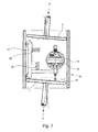
- Figure 3 illustrates a mechanical measuring element 13 for measuring the angle of gyration of a gyratory compactor in accordance with the invention which has been placed inside the body of the loading device 1 illustrated in fig. 1 (in fig. 3 the loading device only partly illustrated for clarity).
- the measuring element 13 includes a dial gauge 14 fixed to a separate frame 19 inside the loading device.
- the dial gauge has been adjusted by means of the frame 19 inside the loading device such that the measuring probe 15 reaches through a hole in a lower head surface of the loading device and touches the bottom 8 of the specimen cylinder mold at a certain point. This point is always located at the same distance from the vertical center line of the loading device 1.
- the dial gauge 14 fixed to the frame 19 measures the angle of gyration of the gyratory compactor exactly during the use of the gyratory compactor regardless of possible small clearances between the loading device and the specimen cylinder mold.
- the dial gauge 14 includes a transmitter 16 in order to transmit the results measured by the dial gauge outside the loading device and the gyratory compactor.
- the transmitter has a wireless contact with a measuring result processing unit (not illustrated in fig. 3) placed near the gyratory compactor, such that the measuring results may be transmitted in real-time from the dial gauge to the measuring result processing unit.
- the dial gauge may include an electronic memory unit, in which the measuring results may be saved, and from where the measuring results may be downloaded to the measuring result processing unit after measuring for later processing of the results.
- the measuring result processing unit is a computer.
- a receiver is included in the computer in order to receive the results from the measuring sent by the transmitter in the dial gauge. If the transmitting of the results is realized after measuring by reading the results from the memory of the dial gauge, a suitable data collection card or corresponding installed in a free expansion slot of the computer is enough to receive the results.
- the computer operating as a measuring result processing unit includes a computer program, which saves the measuring results and defines the angle of gyration and the elastic deformations due to loads on the gyratory compactor due to the loading device as well as the correlation between the deformations and the magnitude of loading.
- the internal angles of a mold in a gyratory compactor may also be measured by one measuring procedure only, by using the diagonal length pick-up like in figure 5.
- This arrangement measures simultaneous the angle of gyration of cover 7 and of bottom 8 during the compaction test with the loading device 1.
- a bearing shaft 29 is placed in the center of the loading device and measuring dial gauges 27 and 28 are fixed by the shaft 29 to the loading device without clearance but easy to move.
- the spherical measuring probe 30 of the dial gauge 27 touches the cover 7 as well as the specimen cylinder wall and the spherical measuring probe 31 of the dial gauge 28 touches the bottom 8 as well as the specimen cylinder wall on the opposite side.
- the dial gauge 27 measures the angle of gyration of the cover and simultaneous the dial gauge 28 measures the angle of gyration of the bottom.
- a variation of this method is to measure without the bearing shaft 29, by one dial gauge only one length position diagonally. This way can measure directly the average internal angle, but this measurement will not give any information of possible differences of the cover 7 motion and bottom 8 motion.
- test method steps can be easily and rapidly performed and repeated in accordance with the invention due to the fact that the mold does not have to be charged or loaded with test specimen material such as soil or asphalt mix in combination with a testing device, emptied, cleaned and reloaded for repeated testing.
- test specimen material such as soil or asphalt mix
- stiffness of the frame and other parts of the gyratory compactor may be different depending the measuring radius direction. Determining this may need more sequences like determined above, by using different radial alignments of the measuring device. In the same way the stiffness of the cover and the bottom of the specimen cylinder mold may be different. These may be found out by turning the measuring probe side of the loading device to the corresponding plate and repeating the measuring sequence.
- Measurements may also be carried out outside the gyratory compactor, for example by adjusting devices sending and/or reflecting a directed light beam to the most important parts of the gyratory compactor.
- This kind of example is illustrated in figure 4 in a measuring arrangement in which there are mirrors 20 adjusted to the specimen cylinder mold, the cover and the bottom of the gyratory compactor, by means of which the elastic deformations are optically defined.
- the measuring solution in accordance with the fig.
- the surface for examining 23 may be arranged, for example, on a suitable vertical surface, such as a paper on a wall where the light beams are reflected. While examining the results the reflecting points of the light beam from the gyratory compactor are marked on the paper with a pen.
- the method in accordance with the invention may be realized in many different ways differing from the earlier explained application example.
- a loading device causing the known loading whatever suitable object/mechanical appliance may be used, the loading of which on the gyratory compactor may be defined on beforehand the way explained above.
- measuring elements differing from what has earlier been presented may be used, such as various optical or mechanical devices measuring directly or indirectly the angle of gyration.
- One method to measure the angle of gyration is to adjust laser approximate sensors in a suitable place on the frame of a gyratory compactor, which measure the motions of the cover and the bottom in regard with the wall of the cylinder mold.
- measuring devices such as those which are able to examine the motions and the changes in motion of the most important parts of a gyratory compactor as the gyratory compactor is in use.
- the measuring elements may be placed/adjusted in various places, such as outside the specimen cylinder mold on the frame of the device or to some other suitable place, where the angle of gyration or the earlier mentioned most important motions of the gyratory compactor and their changes may be measured during the use of the gyratory compactor.
- the measuring result processing unit included in the device in accordance with the invention with which the angle of gyration is defined from the results from the measuring elements as well as the correlation between loading and the elastic deformations are defined may be realized in many various ways differing from the earlier explained application example.
Landscapes
- Physics & Mathematics (AREA)
- Health & Medical Sciences (AREA)
- Life Sciences & Earth Sciences (AREA)
- Chemical & Material Sciences (AREA)
- Analytical Chemistry (AREA)
- Biochemistry (AREA)
- General Health & Medical Sciences (AREA)
- General Physics & Mathematics (AREA)
- Immunology (AREA)
- Pathology (AREA)
- Investigating Strength Of Materials By Application Of Mechanical Stress (AREA)
- Structures Of Non-Positive Displacement Pumps (AREA)
- Applications Or Details Of Rotary Compressors (AREA)
Applications Claiming Priority (4)
| Application Number | Priority Date | Filing Date | Title |
|---|---|---|---|
| FI20020560 | 2002-03-22 | ||
| FI20020560A FI20020560A0 (fi) | 2002-03-22 | 2002-03-22 | Menetelmä ja laitteisto kiertotiivistimen joustojen määrittämiseksi |
| FI20022035A FI119035B (fi) | 2002-03-22 | 2002-11-15 | Menetelmä ja laitteisto kiertotiivistimen joustojen määrittämiseksi |
| FI20022035 | 2002-11-15 |
Publications (3)
| Publication Number | Publication Date |
|---|---|
| EP1348942A2 true EP1348942A2 (de) | 2003-10-01 |
| EP1348942A3 EP1348942A3 (de) | 2006-07-19 |
| EP1348942B1 EP1348942B1 (de) | 2009-10-28 |
Family
ID=26161298
Family Applications (1)
| Application Number | Title | Priority Date | Filing Date |
|---|---|---|---|
| EP03396025A Expired - Lifetime EP1348942B1 (de) | 2002-03-22 | 2003-03-20 | Verfahren und Vorrichtung zur Definition von elastischen Deformationen und Messung des inneren Winkels eines Kreiselverdichters |
Country Status (7)
| Country | Link |
|---|---|
| US (1) | US6904693B2 (de) |
| EP (1) | EP1348942B1 (de) |
| AT (1) | ATE447170T1 (de) |
| AU (1) | AU2003202409B2 (de) |
| CA (1) | CA2422552C (de) |
| DE (1) | DE60329803D1 (de) |
| FI (1) | FI119035B (de) |
Cited By (5)
| Publication number | Priority date | Publication date | Assignee | Title |
|---|---|---|---|---|
| US6889558B2 (en) * | 2001-10-19 | 2005-05-10 | Pine Instrument Company | Real-time display of internal gyration angle in gyratory compaction material testing |
| US6904693B2 (en) | 2002-03-22 | 2005-06-14 | Pine Instrument Company | Method and device for defining elastic deformations and internal angle of a gyratory compactor |
| US6925889B2 (en) | 2002-10-18 | 2005-08-09 | Pine Instrument Company | Devices and methods for applying known resistance loads and measuring internal angles of gyration in gyratory compactors |
| CN111791337A (zh) * | 2020-05-22 | 2020-10-20 | 中交一公局集团有限公司海外分公司 | 成型器、振动检验装置以及沥青用量判断快速检验方法 |
| CN112782066A (zh) * | 2021-02-07 | 2021-05-11 | 贵州省交通规划勘察设计研究院股份有限公司 | 一种用于岩体风化速率高精度测量的装置及其方法 |
Families Citing this family (7)
| Publication number | Priority date | Publication date | Assignee | Title |
|---|---|---|---|---|
| US7121149B2 (en) * | 2003-01-10 | 2006-10-17 | Troxler Electronic Laboratories, Inc. | Gyratory compactor apparatus and associated devices and methods |
| US8261621B2 (en) * | 2009-10-30 | 2012-09-11 | Mott's Llp | Measurement of forces on packaged objects |
| CN104849160A (zh) * | 2015-03-20 | 2015-08-19 | 江苏明珠试验机械有限公司 | 一种辊筒式磨耗机3°检验装置及具备该检验装置的夹转装置及其检验方法 |
| CN106644624A (zh) * | 2016-09-28 | 2017-05-10 | 长安大学 | 一种moh半柔性材料室内旋转压实试验方法 |
| CN110672000A (zh) * | 2019-10-23 | 2020-01-10 | 中国核动力研究设计院 | 适用于压水堆压力容器密封面水平度测量装置及使用方法 |
| CN112729075B (zh) * | 2021-02-05 | 2025-01-24 | 南京东永神富科技有限公司 | 一种角度计测量装置 |
| CN115900509B (zh) * | 2023-03-03 | 2023-04-28 | 山东柏远复合材料科技股份有限公司 | 一种圆形缸筒变形度检测工装 |
Family Cites Families (31)
| Publication number | Priority date | Publication date | Assignee | Title |
|---|---|---|---|---|
| US89178A (en) * | 1869-04-20 | Improvement in saw-mills | ||
| US49969A (en) * | 1865-09-19 | Improved apparatus for packing rubber for dental purposes | ||
| US192384A (en) * | 1877-06-26 | Improvement in the method of securing pictures | ||
| US2972249A (en) | 1958-02-20 | 1961-02-21 | John L Mcrae | Kneader compactor |
| US3461717A (en) | 1968-03-29 | 1969-08-19 | Wayne A Dunlap | Gyratory compactor |
| US3478572A (en) | 1968-07-12 | 1969-11-18 | John L Mcrae | Wall friction device |
| CH588683A5 (de) | 1975-07-28 | 1977-06-15 | Concast Ag | |
| CH630174A5 (de) * | 1978-04-05 | 1982-05-28 | Hans Meyer | Innenmessgeraet. |
| FI71619C (fi) | 1985-04-03 | 1987-01-19 | Partek Ab | Foerfarande och apparat foer maetning av egenskaperna speciellt foertaetningsbarheten av en troeg, gjutbar massa. |
| FI75672C (fi) | 1986-10-02 | 1988-07-11 | Ilmari Paakkinen | Foerfarande foer maetning av egenskaper hos formbara material, saerskilt plastiska och reologiska egenskaper. |
| US4918825A (en) * | 1989-01-23 | 1990-04-24 | Lesh Stephen S | Micrometer cartridge headspace gauge |
| US5036709A (en) | 1989-06-06 | 1991-08-06 | Mcrae John L | Paving materials testing machine |
| US4942768A (en) | 1989-06-06 | 1990-07-24 | Mcrae John L | Paving material testing machine |
| US5275056A (en) | 1992-10-20 | 1994-01-04 | Rainhart Co. | Gyratory shear material compacting device |
| US5323655A (en) | 1993-04-23 | 1994-06-28 | Troxler Electronic Laboratories, Inc. | Method and apparatus for compacting material samples |
| FI96243C (fi) | 1993-10-26 | 1996-05-27 | Ilmari Paakkinen | Menetelmä ja laite rakeisten maamassojen ominaisuuksien mittaamiseksi |
| US5456118A (en) | 1994-02-18 | 1995-10-10 | Pine Instrument Company | Gyratory compactor |
| US5606133A (en) * | 1995-10-06 | 1997-02-25 | Pine Instrument Company | Gyratory compactor with mold specimen extruder |
| US5817946A (en) * | 1996-10-28 | 1998-10-06 | Test Quip, Inc. | Gyratory compaction apparatus for creating compression and shear forces in a sample material |
| US5824913A (en) * | 1997-01-10 | 1998-10-20 | Pine Instrument Company | Portable gyratory compactor and extruder with a single pivot and two gyration actuators |
| US5911164A (en) | 1998-02-10 | 1999-06-08 | Mcrae; John L. | Compaction and pavement design testing machine and method for testing flexible pavement materials |
| US5939642A (en) * | 1998-03-25 | 1999-08-17 | Troxler Electronic Laboratories, Inc. | Gyratory compactor |
| FR2781283B1 (fr) | 1998-07-15 | 2000-10-06 | France Etat Ponts Chaussees | Presse a cisaillement giratoire |
| JP2000205852A (ja) * | 1999-01-19 | 2000-07-28 | Mitsutoyo Corp | デジタルアナログ併用表示型測定器のアナログ量測定・表示方法 |
| US6694823B2 (en) | 2000-03-23 | 2004-02-24 | Wisconsin Alumni Research Foundation | Apparatus and method for testing material performance |
| FI114171B (fi) | 2000-05-12 | 2004-08-31 | Antti Paakkinen | Menetelmä ja laite maamassojen ja muiden niiden kaltaisten massojen tiivistysominaisuuksien mittaamiseksi |
| US6477783B1 (en) | 2000-09-19 | 2002-11-12 | The United States Of America As Represented By The Secretary Of Transportation | Gyratory compactor angle measurement device |
| US6889558B2 (en) * | 2001-10-19 | 2005-05-10 | Pine Instrument Company | Real-time display of internal gyration angle in gyratory compaction material testing |
| FI119035B (fi) | 2002-03-22 | 2008-06-30 | Antti Paakkinen | Menetelmä ja laitteisto kiertotiivistimen joustojen määrittämiseksi |
| US20030192384A1 (en) | 2002-04-11 | 2003-10-16 | Troxler Electronic Laboratories, Inc. | In-mold pressure verification device |
| US6868738B2 (en) * | 2002-07-31 | 2005-03-22 | Troxler Electronic Laboratories, Inc. | Method and apparatus for determining the angle of gyration and/or the pressure in a gyratory compactor |
-
2002
- 2002-11-15 FI FI20022035A patent/FI119035B/fi active IP Right Grant
-
2003
- 2003-03-19 CA CA2422552A patent/CA2422552C/en not_active Expired - Fee Related
- 2003-03-20 EP EP03396025A patent/EP1348942B1/de not_active Expired - Lifetime
- 2003-03-20 DE DE60329803T patent/DE60329803D1/de not_active Expired - Fee Related
- 2003-03-20 AT AT03396025T patent/ATE447170T1/de not_active IP Right Cessation
- 2003-03-21 US US10/394,633 patent/US6904693B2/en not_active Expired - Lifetime
- 2003-03-21 AU AU2003202409A patent/AU2003202409B2/en not_active Ceased
Cited By (7)
| Publication number | Priority date | Publication date | Assignee | Title |
|---|---|---|---|---|
| US6889558B2 (en) * | 2001-10-19 | 2005-05-10 | Pine Instrument Company | Real-time display of internal gyration angle in gyratory compaction material testing |
| US6904693B2 (en) | 2002-03-22 | 2005-06-14 | Pine Instrument Company | Method and device for defining elastic deformations and internal angle of a gyratory compactor |
| US6925889B2 (en) | 2002-10-18 | 2005-08-09 | Pine Instrument Company | Devices and methods for applying known resistance loads and measuring internal angles of gyration in gyratory compactors |
| CN111791337A (zh) * | 2020-05-22 | 2020-10-20 | 中交一公局集团有限公司海外分公司 | 成型器、振动检验装置以及沥青用量判断快速检验方法 |
| CN111791337B (zh) * | 2020-05-22 | 2021-09-21 | 中交一公局集团有限公司 | 成型器、振动检验装置以及沥青用量判断快速检验方法 |
| WO2021232869A1 (zh) * | 2020-05-22 | 2021-11-25 | 中交一公局集团有限公司 | 成型器、振动检验装置以及沥青用量判断快速检验方法 |
| CN112782066A (zh) * | 2021-02-07 | 2021-05-11 | 贵州省交通规划勘察设计研究院股份有限公司 | 一种用于岩体风化速率高精度测量的装置及其方法 |
Also Published As
| Publication number | Publication date |
|---|---|
| EP1348942A3 (de) | 2006-07-19 |
| DE60329803D1 (de) | 2009-12-10 |
| FI119035B (fi) | 2008-06-30 |
| US20040181956A1 (en) | 2004-09-23 |
| CA2422552C (en) | 2010-03-16 |
| FI20022035A7 (fi) | 2003-09-23 |
| ATE447170T1 (de) | 2009-11-15 |
| EP1348942B1 (de) | 2009-10-28 |
| FI20022035A0 (fi) | 2002-11-15 |
| AU2003202409A1 (en) | 2003-10-16 |
| CA2422552A1 (en) | 2003-09-22 |
| US6904693B2 (en) | 2005-06-14 |
| AU2003202409B2 (en) | 2009-06-04 |
Similar Documents
| Publication | Publication Date | Title |
|---|---|---|
| US6904693B2 (en) | Method and device for defining elastic deformations and internal angle of a gyratory compactor | |
| US5269190A (en) | Apparatus for the performance of rheological measurements on materials | |
| US5757473A (en) | Optical strain sensor for the measurement of microdeformations of surfaces | |
| US5616857A (en) | Penetration hardness tester | |
| AU2002351886B2 (en) | Soil or snow probe | |
| CN100412526C (zh) | 材料试验机的压痕测试功能改进方法及其改进装置 | |
| RU2192006C2 (ru) | Способ определения физико-механических характеристик слоя почвогрунта, преимущественно имеющего низкую и среднюю плотность, и устройство для его осуществления | |
| US6477783B1 (en) | Gyratory compactor angle measurement device | |
| US6055866A (en) | Process and device for checking the solidity of vertically anchored masts | |
| US5365457A (en) | In situ dynamic material property measurement system | |
| US6889558B2 (en) | Real-time display of internal gyration angle in gyratory compaction material testing | |
| CN104729938B (zh) | 一种基于机电阻抗法的便携式硬度检测结构及其检测方法 | |
| US4862735A (en) | Microviscometer | |
| US6925889B2 (en) | Devices and methods for applying known resistance loads and measuring internal angles of gyration in gyratory compactors | |
| CN115310168B (zh) | 一种高铁填料振动压实力学状态评估方法及系统 | |
| JPH05506305A (ja) | 超音波コンタクトインピーダンス方法における、荷重印加の基での硬さ又は弾性材料特性の測定方法 | |
| CN119334793B (zh) | 一种用于监测边坡剪切变形的直剪模型装置 | |
| RU2163715C1 (ru) | Устройство для испытания на сжатие | |
| RU2803712C1 (ru) | Способ определения фактической плотности грунтов при помощи построения 3d модели лунки | |
| Allersma | Optical analysis of stress and strain in shear zones | |
| SU838092A1 (ru) | Устройство дл определени прочностиХРупКиХ МАТЕРиАлОВ HA СжАТиЕ | |
| SU1272240A1 (ru) | Прибор дл определени сопротивл емости образца клейковины сжатию | |
| SU932371A1 (ru) | Способ определени твердости материалов | |
| SU748190A1 (ru) | Конический пластометр | |
| SU624148A1 (ru) | Устройство дл определени тонины волокна |
Legal Events
| Date | Code | Title | Description |
|---|---|---|---|
| PUAI | Public reference made under article 153(3) epc to a published international application that has entered the european phase |
Free format text: ORIGINAL CODE: 0009012 |
|
| 17P | Request for examination filed |
Effective date: 20030409 |
|
| AK | Designated contracting states |
Kind code of ref document: A2 Designated state(s): AT BE BG CH CY CZ DE DK EE ES FI FR GB GR HU IE IT LI LU MC NL PT RO SE SI SK TR |
|
| AX | Request for extension of the european patent |
Extension state: AL LT LV MK |
|
| PUAL | Search report despatched |
Free format text: ORIGINAL CODE: 0009013 |
|
| AK | Designated contracting states |
Kind code of ref document: A3 Designated state(s): AT BE BG CH CY CZ DE DK EE ES FI FR GB GR HU IE IT LI LU MC NL PT RO SE SI SK TR |
|
| AX | Request for extension of the european patent |
Extension state: AL LT LV MK |
|
| 17Q | First examination report despatched |
Effective date: 20061208 |
|
| AKX | Designation fees paid |
Designated state(s): AT BE BG CH CY CZ DE DK EE ES FI FR GB GR HU IE IT LI LU MC NL PT RO SE SI SK TR |
|
| GRAP | Despatch of communication of intention to grant a patent |
Free format text: ORIGINAL CODE: EPIDOSNIGR1 |
|
| GRAS | Grant fee paid |
Free format text: ORIGINAL CODE: EPIDOSNIGR3 |
|
| GRAA | (expected) grant |
Free format text: ORIGINAL CODE: 0009210 |
|
| AK | Designated contracting states |
Kind code of ref document: B1 Designated state(s): AT BE BG CH CY CZ DE DK EE ES FI FR GB GR HU IE IT LI LU MC NL PT RO SE SI SK TR |
|
| REG | Reference to a national code |
Ref country code: GB Ref legal event code: FG4D |
|
| REG | Reference to a national code |
Ref country code: CH Ref legal event code: EP |
|
| REG | Reference to a national code |
Ref country code: IE Ref legal event code: FG4D |
|
| REF | Corresponds to: |
Ref document number: 60329803 Country of ref document: DE Date of ref document: 20091210 Kind code of ref document: P |
|
| NLV1 | Nl: lapsed or annulled due to failure to fulfill the requirements of art. 29p and 29m of the patents act | ||
| PG25 | Lapsed in a contracting state [announced via postgrant information from national office to epo] |
Ref country code: ES Free format text: LAPSE BECAUSE OF FAILURE TO SUBMIT A TRANSLATION OF THE DESCRIPTION OR TO PAY THE FEE WITHIN THE PRESCRIBED TIME-LIMIT Effective date: 20100208 Ref country code: SE Free format text: LAPSE BECAUSE OF FAILURE TO SUBMIT A TRANSLATION OF THE DESCRIPTION OR TO PAY THE FEE WITHIN THE PRESCRIBED TIME-LIMIT Effective date: 20091028 Ref country code: PT Free format text: LAPSE BECAUSE OF FAILURE TO SUBMIT A TRANSLATION OF THE DESCRIPTION OR TO PAY THE FEE WITHIN THE PRESCRIBED TIME-LIMIT Effective date: 20100301 Ref country code: FI Free format text: LAPSE BECAUSE OF FAILURE TO SUBMIT A TRANSLATION OF THE DESCRIPTION OR TO PAY THE FEE WITHIN THE PRESCRIBED TIME-LIMIT Effective date: 20091028 |
|
| PG25 | Lapsed in a contracting state [announced via postgrant information from national office to epo] |
Ref country code: SI Free format text: LAPSE BECAUSE OF FAILURE TO SUBMIT A TRANSLATION OF THE DESCRIPTION OR TO PAY THE FEE WITHIN THE PRESCRIBED TIME-LIMIT Effective date: 20091028 Ref country code: CY Free format text: LAPSE BECAUSE OF FAILURE TO SUBMIT A TRANSLATION OF THE DESCRIPTION OR TO PAY THE FEE WITHIN THE PRESCRIBED TIME-LIMIT Effective date: 20091028 |
|
| PG25 | Lapsed in a contracting state [announced via postgrant information from national office to epo] |
Ref country code: AT Free format text: LAPSE BECAUSE OF FAILURE TO SUBMIT A TRANSLATION OF THE DESCRIPTION OR TO PAY THE FEE WITHIN THE PRESCRIBED TIME-LIMIT Effective date: 20091028 Ref country code: BE Free format text: LAPSE BECAUSE OF FAILURE TO SUBMIT A TRANSLATION OF THE DESCRIPTION OR TO PAY THE FEE WITHIN THE PRESCRIBED TIME-LIMIT Effective date: 20091028 |
|
| PG25 | Lapsed in a contracting state [announced via postgrant information from national office to epo] |
Ref country code: RO Free format text: LAPSE BECAUSE OF FAILURE TO SUBMIT A TRANSLATION OF THE DESCRIPTION OR TO PAY THE FEE WITHIN THE PRESCRIBED TIME-LIMIT Effective date: 20091028 Ref country code: DK Free format text: LAPSE BECAUSE OF FAILURE TO SUBMIT A TRANSLATION OF THE DESCRIPTION OR TO PAY THE FEE WITHIN THE PRESCRIBED TIME-LIMIT Effective date: 20091028 Ref country code: EE Free format text: LAPSE BECAUSE OF FAILURE TO SUBMIT A TRANSLATION OF THE DESCRIPTION OR TO PAY THE FEE WITHIN THE PRESCRIBED TIME-LIMIT Effective date: 20091028 Ref country code: BG Free format text: LAPSE BECAUSE OF FAILURE TO SUBMIT A TRANSLATION OF THE DESCRIPTION OR TO PAY THE FEE WITHIN THE PRESCRIBED TIME-LIMIT Effective date: 20100128 |
|
| PG25 | Lapsed in a contracting state [announced via postgrant information from national office to epo] |
Ref country code: SK Free format text: LAPSE BECAUSE OF FAILURE TO SUBMIT A TRANSLATION OF THE DESCRIPTION OR TO PAY THE FEE WITHIN THE PRESCRIBED TIME-LIMIT Effective date: 20091028 Ref country code: CZ Free format text: LAPSE BECAUSE OF FAILURE TO SUBMIT A TRANSLATION OF THE DESCRIPTION OR TO PAY THE FEE WITHIN THE PRESCRIBED TIME-LIMIT Effective date: 20091028 |
|
| PLBE | No opposition filed within time limit |
Free format text: ORIGINAL CODE: 0009261 |
|
| STAA | Information on the status of an ep patent application or granted ep patent |
Free format text: STATUS: NO OPPOSITION FILED WITHIN TIME LIMIT |
|
| 26N | No opposition filed |
Effective date: 20100729 |
|
| PG25 | Lapsed in a contracting state [announced via postgrant information from national office to epo] |
Ref country code: GR Free format text: LAPSE BECAUSE OF FAILURE TO SUBMIT A TRANSLATION OF THE DESCRIPTION OR TO PAY THE FEE WITHIN THE PRESCRIBED TIME-LIMIT Effective date: 20100129 Ref country code: MC Free format text: LAPSE BECAUSE OF NON-PAYMENT OF DUE FEES Effective date: 20100331 |
|
| REG | Reference to a national code |
Ref country code: CH Ref legal event code: PL |
|
| PG25 | Lapsed in a contracting state [announced via postgrant information from national office to epo] |
Ref country code: IE Free format text: LAPSE BECAUSE OF NON-PAYMENT OF DUE FEES Effective date: 20100320 |
|
| PG25 | Lapsed in a contracting state [announced via postgrant information from national office to epo] |
Ref country code: DE Free format text: LAPSE BECAUSE OF NON-PAYMENT OF DUE FEES Effective date: 20101001 Ref country code: LI Free format text: LAPSE BECAUSE OF NON-PAYMENT OF DUE FEES Effective date: 20100331 Ref country code: CH Free format text: LAPSE BECAUSE OF NON-PAYMENT OF DUE FEES Effective date: 20100331 |
|
| PG25 | Lapsed in a contracting state [announced via postgrant information from national office to epo] |
Ref country code: LU Free format text: LAPSE BECAUSE OF NON-PAYMENT OF DUE FEES Effective date: 20100320 Ref country code: HU Free format text: LAPSE BECAUSE OF FAILURE TO SUBMIT A TRANSLATION OF THE DESCRIPTION OR TO PAY THE FEE WITHIN THE PRESCRIBED TIME-LIMIT Effective date: 20100429 Ref country code: NL Free format text: LAPSE BECAUSE OF FAILURE TO SUBMIT A TRANSLATION OF THE DESCRIPTION OR TO PAY THE FEE WITHIN THE PRESCRIBED TIME-LIMIT Effective date: 20091028 |
|
| PG25 | Lapsed in a contracting state [announced via postgrant information from national office to epo] |
Ref country code: TR Free format text: LAPSE BECAUSE OF FAILURE TO SUBMIT A TRANSLATION OF THE DESCRIPTION OR TO PAY THE FEE WITHIN THE PRESCRIBED TIME-LIMIT Effective date: 20091028 |
|
| PGFP | Annual fee paid to national office [announced via postgrant information from national office to epo] |
Ref country code: FR Payment date: 20140312 Year of fee payment: 12 |
|
| PGFP | Annual fee paid to national office [announced via postgrant information from national office to epo] |
Ref country code: GB Payment date: 20140319 Year of fee payment: 12 |
|
| GBPC | Gb: european patent ceased through non-payment of renewal fee |
Effective date: 20150320 |
|
| REG | Reference to a national code |
Ref country code: FR Ref legal event code: ST Effective date: 20151130 |
|
| PG25 | Lapsed in a contracting state [announced via postgrant information from national office to epo] |
Ref country code: GB Free format text: LAPSE BECAUSE OF NON-PAYMENT OF DUE FEES Effective date: 20150320 |
|
| PG25 | Lapsed in a contracting state [announced via postgrant information from national office to epo] |
Ref country code: FR Free format text: LAPSE BECAUSE OF NON-PAYMENT OF DUE FEES Effective date: 20150331 |
|
| PGFP | Annual fee paid to national office [announced via postgrant information from national office to epo] |
Ref country code: IT Payment date: 20210204 Year of fee payment: 19 |
|
| PG25 | Lapsed in a contracting state [announced via postgrant information from national office to epo] |
Ref country code: IT Free format text: LAPSE BECAUSE OF NON-PAYMENT OF DUE FEES Effective date: 20220320 |